the Creative Commons Attribution 4.0 License.
the Creative Commons Attribution 4.0 License.
 | 22 Jul 2020
Influence of flex-sub on mechanical properties of rotary steerable drilling system
Jin Wang
Lixin Li
Leilei Huang
Fangtao Li
Baolin Liu
In this paper we analysis of the dynamic model of the Rotary Steerable System (RSS) with a single stabilizer and flex-sub. The drill collar and joint are simplified to obtain suitable bottom-hole assembly (BHA) model of mechanical analysis and finite element analysis. Using the BHA uniform stiffness assumption (ignoring the influence of variable section and variable stiffness of drill collar in BHA), the paper takes a method of the longitudinal and transverse bending continuous beam method to analyse the stress of BHA with RSS with the flex-sub under different inclination angles and curvature conditions. In addition, a dynamic analysis model is proposed, and the dynamic stress of drilling tools with RSS is analysed. Through the software of ANSYS, the finite element analysis of the RSS with the flex-sub is carried out to verify the theoretical results. The influence of flex-sub on the steering drilling performance of RSS is studied, and the optimized parameters of flex-sub design are obtained, which provides useful suggestions for the design of RSS.
- Article
(7881 KB) - Full-text XML
- BibTeX
- EndNote


In the field of oil & gas drilling engineering, the Rotary Steerable System (RSS) is very widely used in directional drilling, the whole drillstring is rotated from the surface by a hydraulically driven top drive. RSS is a new form of drilling technology used in directional drilling. It employs the use of specialized downhole equipment to replace conventional directional tools such as mud motors. The methods used to direct the well path fall into two broad categories, these being “push-the-bit” or “point-the-bit” (Wilson and Heisig, 2015; Barr et al., 2000). Push-the-bit RSS use pads on the outside of the tool which press against the well bore thereby causing the bit to press on the opposite side causing a direction change. The pads of the implementing agencies in RSS constantly pushed against the borehole wall, making bottom hole by a cycle of nonlinear damping force, which is lead to the bottom drilling tool movement of chaos and disorder (Xue et al., 2016).
Actually, drillstring dynamics (Ritto et al., 2013) is one of the most important problem which is attracted the attention of engineers for more than half a century. The drillstring is consisted of several drill pipes, drill collars, including various drilling tools such as RSS, stabilizers and connections, under heavy dynamic loads with extreme complexity (Liu et al., 2014). There are three typical modes of drillstring vibration, namely are the longitudinal vibration (also called axial vibration), lateral vibration and the torsional vibration (stick-slip in case of verification) (Liu et al., 2013). Bailey and Finnie (1960) derived the axial natural frequencies of drillstring by partial differential equation with an undamped model of longitudinal bar vibration. Then the classical linear-damped axial wave equation was proposed by Kreisle and Vance (1970) as the governing equation, which can be solved by using the Laplace transformation. Then, the effect of the length of the bottom hole assembly (BHA) on the axial resonance of the drillstring is studied by Dareing (1984a, b) with a developed damped axial wave equation. The axial vibrations of the drillstring using discrete mass segments and springs was modelled by Elsayed and Phung (2005), the comparative analysis of the response of real drillstring and the model was carried out by frequency response function (FRF), and the similarity is proven. Lubinski (1988) was one of the earliest researchers who studied the dynamics of drillstring. Furthermore, the friction between the drillstring and the wellbore during tripping motion was investigated by Aadnoy et al. (2010), and the fiction reduction method using the rotation of the drillstring was proposed.
The RSS technology developed rapidly since the 1990s has effectively compensated for the problem of poor slanting ability and low drilling efficiency of traditional directional drilling tools, which can realize flexible and precise control of complex well trajectories and reduce drilling operation costs and improve the success rate of drilling and the benefits of exploration. The rotary steerable drilling technology have gradually developed into one of the most core technologies of modern drilling engineering (Carpenter, 2014; Greenwood, 2018; Warren, 1998). The guiding ability of RSS can be expressed by its lateral cutting capacity (Xue et al., 2016, 2019). The lateral cutting capacity can be characterized by the deflection rate. The basic factors affecting the drilling deflection rate are (Santos et al., 2014): the bit characteristics, the BHA structure, and the RSS dynamics, wellbore geometries, drilling technology and formation properties. BHA is an important factor affecting the ability of the RSS to make the slanting (Sarker et al., 2017; Di et al., 2012). The design of the flex sub is directly related to the mechanical properties and safety of the BHA, which finally affects the realization of the lateral cutting capacity of the RSS. Therefore, the design of the flexible short section is one of the most critical part of the BHA design for RSS.
The research on flexible short sections mainly focuses on the influence of flex sub on stress and dynamic characteristics of integral drillstring and BHA (Su et al., 2004; Panayirci et al., 2015; Huang et al., 2013). However, there are relatively few studies on the influence of the flex sub in the directional drilling process on the guiding ability of the RSS. Therefore, in order to better utilize the directional drilling capability of the rotary steerable drilling tool during the drilling process, further research and analysis should be carried out in combination with the development of the rotary steerable drilling tool engineering prototype, aiming to provide suggestions based on theoretical analysis for the design and optimization of flex sub.
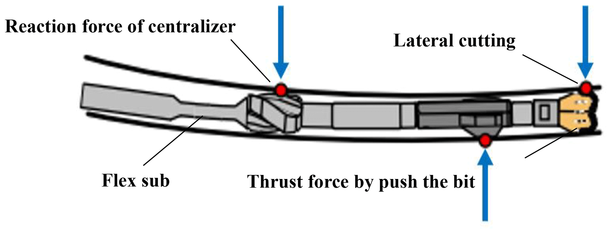
This paper mainly analyses the push the bit RSS. Based on the three-dimensional modelling of BHA, the simplified of BHA is analysed by the longitudinal and transverse curved continuous beam theory to provide evaluation basis for the subsequent finite element simulation (Verdam and Schouten, 2013). As shown in the Fig. 1, in the process of work, the pads will be pushed to the set tool face of the borehole by hydraulic pressure. After a period of time, the one of pads is turned off, the next one is turned on, and in this way the full-rotation dynamic correction is realized. Wellbore trajectory changed due to lateral cutting, in this process, flex sub plays a key role.
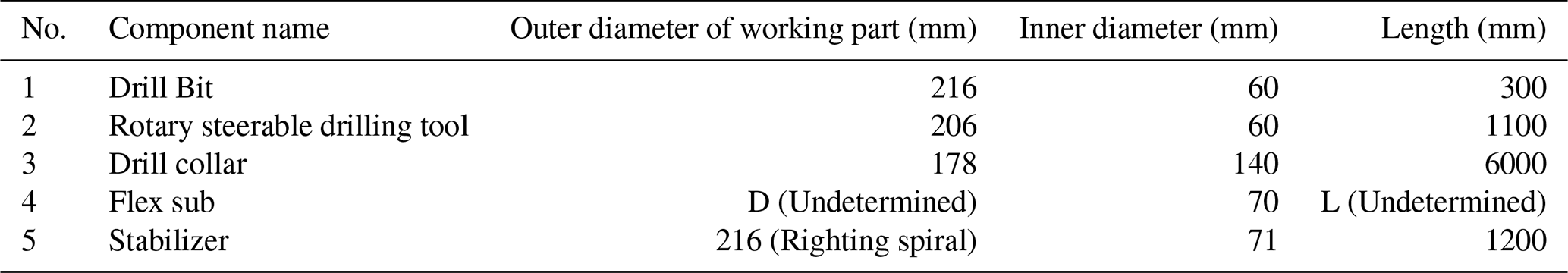
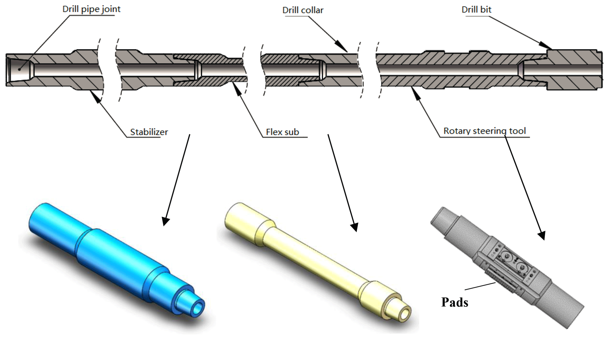
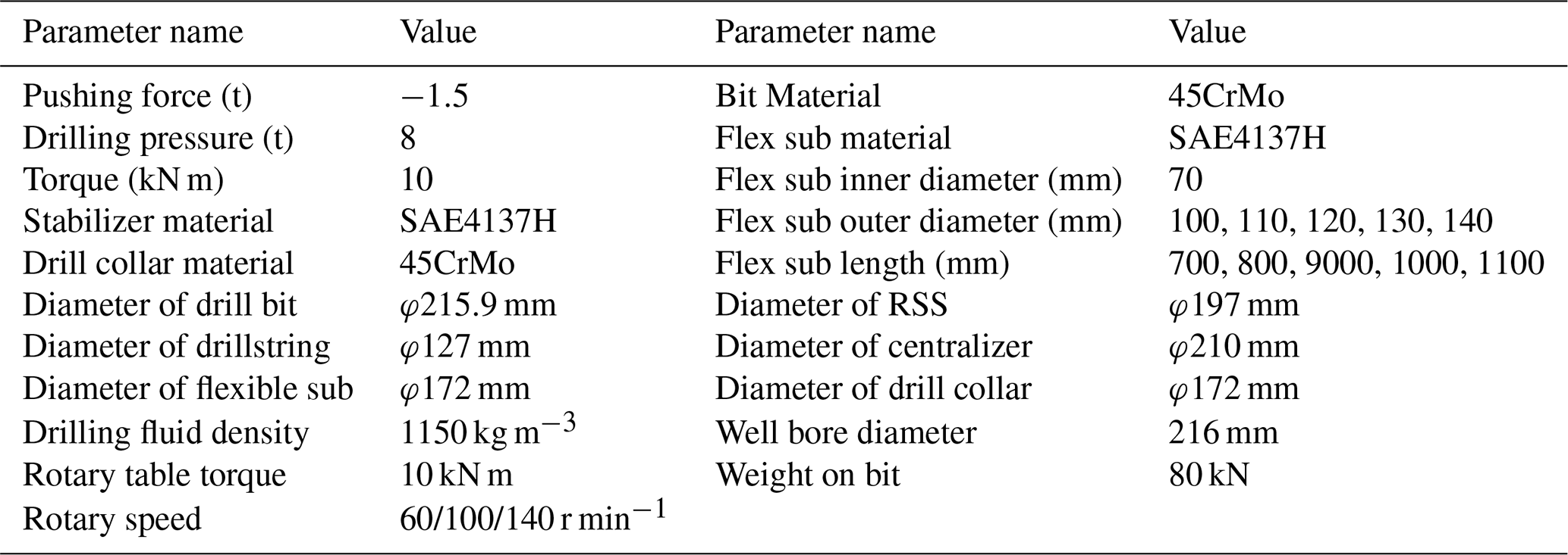
The influence of the flex sub on the guiding ability of the RSS is mainly concentrated on the portion of the bottom BHA close to the drill bit. The BHA structure for the RSS is shown in Fig. 2. In order to facilitate the subsequent analysis, the connection threads of each component in the BHA, including the stabilizer, the flex sub and RSS, are simplified on the basis of the API standard. The structure parameters are also shown in Table 1.
Table 1Structural parameters of the BHA for Rotary Steering Drilling Tool.
3.1 Mechanical model of BHA for RSS
The longitudinal and transverse curved continuous beam method is used to analyse the mechanical properties of BHA (Sloboda and Honarmandi, 2007; Rattanawangcharoen et al., 2004). The mechanical model has the following assumptions:
-
BHA is a small elastic deformation system;
-
The center of the bottom of the drill bit is located on the center line of the wellbore, and there is no couple between the drill bit and the ground layer;
-
The drilling pressure is constant and acts along the axis of the wellbore;
-
The well wall is an ideal rigid body, and the size of the wellbore does not change;
-
The drillstring section remains unchanged and there is no initial bending;
In the process of rotary steerable drilling, the BHA mechanical analysis can ignore the change of the well trajectory in the azimuth. Therefore, the analysis uses a two-dimensional well body plane, as shown in Fig. 3a. Schematic diagram of two-dimensional well structure of rotary steerable drilling tool with single stabilizer is shown in Fig. 3b. The origin of the plane rectangular coordinate system is at the center of the bottom surface of the drill bit, the x-axis direction is the tangential direction of the wellbore axis, the y-axis is perpendicular to the x-axis, then the curve equation of the well trajectory can be approximated as follows:
wherein, ρT – Curvature radius of wellbore trajectory curve between measuring points A and B.
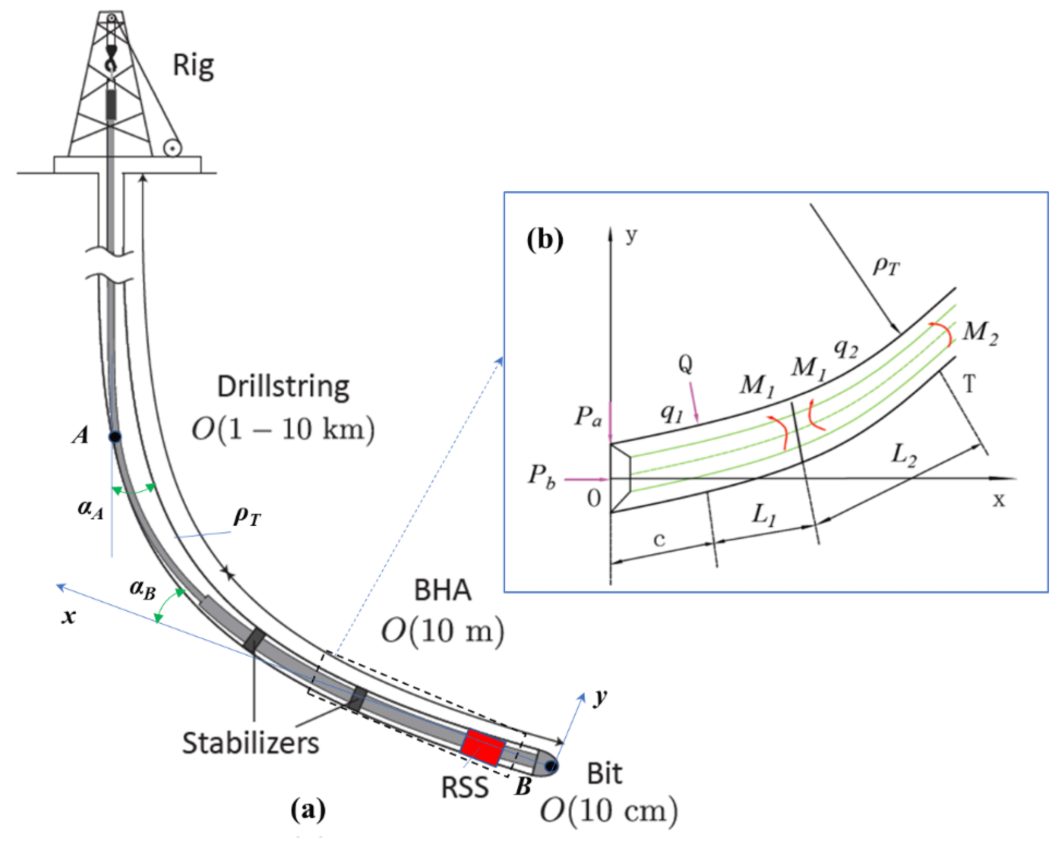
Figure 3Schematic diagram of BHA. (a) Two-dimensional well structure; (b) Two-dimensional well structure of RSS with single stabilizer.
If the well depth and the well angle measured at points A and B in Fig. 3a are LA, LB and αA, αB, respectively, the radius of curvature of the well trajectory curve can be approximated by the following equations.
wherein ΔS is the arc length of the wellbore trajectory between points A and B (m); ΔL is the depth of wellbore trajectory between points A and B (m).
The vertical and horizontal curved continuous beam method considers the contact point between the stabilizer and the upper drill pipe (or drill collar) in the BHA as the fulcrum, thereby establishing a simply supported beam that is affected by the uniform load (gravity) and the end force couple. As shown in Fig. 4, the bending angle caused by deformation on both sides of the simply supported beam has the following relationship:
wherein, is bending angle of right side of the ith span simply supported beam from BHA. is Bending angle of left side of the ith span simply supported beam from BHA.
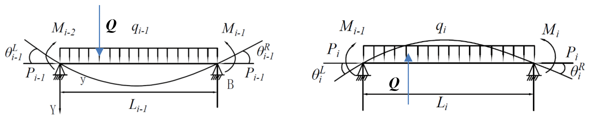
Figure 4Schematic diagram of continuous beam method for longitudinal and transverse bending.
A constant concentrated force Q will be applied to the shaft wall, represents the force perpendicular to the drill string axis, so called by the radial force. As shown in Fig. 4, the concentrated force forms an additional angle on the right side of the first span simply supported beam:
Where, – Additional angle formed by concentrated load on the right side of the first span simply supported beam; – Computational factors for simplifying the form of equations; c – Distance between pushing position and bottom of drill bit.
Using Eq. (4), the three-moment equations for a push the bit RSS with a single stabilizer will be obtained (Su et al., 2004):
In Eq. (5), according to assumptions M0=0, there are only two parameters M1, M2 unknowns. According to the solution of Eq. (5), the lateral cutting force of the RSS and the rotation angle of the bit can be obtained from the basic equations of material mechanics. From top to bottom of the BHA, the centroid of the first stabilizer section is the centroid of the bending moment equation. The lateral cutting force of the drill bit is obtained from the established bending moment equation, as shown in Eq. (6).
The rotation angle of the bit as shown in Eq. (7).
Where, Pa – Lateral cutting force of the drill bit (N); Ab – Rotation angle of drill bit.
The meaning and solution method of each parameter in Eqs. (5)–(7): qi – Radial force of simply supported beam located at the ith span of BHA from up to bottom (averaging uniform load) (N); X(ui), Y(ui), Z(ui) – Parameters allowing to take into account the influence of the longitudinal forces on the bending of the rod; Li – Length of simply supported beam located at the ith span of BHA from up to bottom (m); Mi – Force couple of simply supported beam located at the ith span of BHA from up to bottom (N m); E – Elastic modulus of steel (Pa);
wherein Pb – Drilling pressure (N); ρωi – Weight of simply supported beam located at the ith span of BHA from up to bottom (Linear Weight) (N m−3); β – Deviation angle (∘). DB – Diameter of bit (m); DS – Diameter of stabilizer (m); DC – Diameter of the drill collar at the upper cut point (m). Doi, Dii – Outer diameter and inner diameter of simply supported beam located at the ith span of BHA from up to bottom (m); Pi – Axial force of simply supported beam located at the ith span of BHA from up to bottom (averaging uniform load) (N).
3.2 Dynamics model
Drillstring actual working condition is very complex, and it's hard to simulate and analyse the actual working condition precisely. Due to the complexity of the drilling operation, the mathematical calculation model cannot effectively explain the fatigue failure of the drillstring caused by the cyclic stress due to vibration and high shock. Since the dynamics of the drillstring involve wide vibration profiles including axial, lateral and torsional modes, the mathematical modelling of such long rotating components is highly nonlinearity. The BHA calculation model of the RSS is shown in Fig. 5, making the following assumptions in the calculation process of the entire dynamic system.
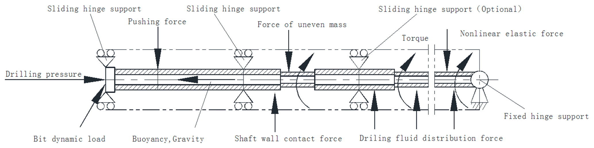
The drillstring is a variable-section, variable-stiffness rotating long axis that is confined inside the borehole, and the gap between it and the borehole wall also changes due to irregularities in the borehole and changes in the outer diameter of the drilling tool. The calculation of the dynamic characteristics of the drillstring is actually a dynamic problem including geometric nonlinearity and contact nonlinearity. In actual engineering, the ground equipment drives the drillstring to rotate. Under the restriction of the borehole, the drill string collides with the well wall from time to time, and the collision position is constantly changing, so that the actual drillstring movement is a collection of rotation and revolution Including longitudinal vibration, torsional vibration, lateral vibration and eddy. The dynamics equation of the drillstring (Melakhessou et al., 2003; Dunayevsky et al., 1993) system can be generally expressed as:
Where , , {U}, {F} are generalized acceleration, velocity, displacement, and external force vector. [M], [C], [K] are mass matrix, damping matrix and stiffness matrix.
Based on the drillstring dynamics calculation model, the mathematical expression of the Hamilton principle of the non-conservative system is:
wherein T is the total kinetic energy of the system; V is the potential energy of the system, including strain energy and potential energy of any conservative external forces; fc is non-conservative force acting on the system; δ is variations taken within the specified time interval.
Then, the model of drillstring system dynamics can be derived as follows:
wherein u is the node displacement; M is the mass matrix; Fm is the distribution force of mud; Fw is the well wall contact force; Fg is the nonlinear elastic force; R is the static force (gravity, buoyancy, weight on bit, etc.); Fe is excitation force (uneven mass, axial bit load, lateral bit load, etc.).
The contact force with the wellbore is normal contact force Fn and tangential contact force Ft, which is expressed as follows
wherein, Kn is normal contact stiffness; un is contact gap.
wherein, Kt is tangential contact stiffness; μ is the coefficient of friction between the drillstring and the borehole wall; uT is contact sliding distance.
The force on the bit of the RSS bottom drill assembly includes two parts, one component is the axial bit force, the other component is the lateral force (the reaction force of the bit in lateral contact), and both are dynamic forces. The expression is as follows:
wherein, Fb is the contact force of drill bit; Fc is the amplitude of reaction force of lateral contact; Fz is axial excitation force amplitude; Ω is excitation angular frequency, rad s−1; i, k is unit direction vector.
In practical application, it is necessary to choose and specify its specific stress form and stress conditions. According to the working characteristics of RSS, consider the load of the tool's active excitation force, contact collision, weight on bit, torque, mud distribution force, nonlinear elastic force, inertial force, etc. Distributed force, non-linear elastic force, here ignore the mass uneven force.
3.3 Methods of finite element simulation
To verify the feasibility of the design of this paper, the three-dimensional analysis model of RSS is established in software of Solidworks. The simulation was carried out using the software of ANSYS 19.0, which uses the finite-element numerical method for solving the dynamics equations. The whole 3D geometry model of the RSS was established using ANSYS Workbench, and grids were generated using the pre-processing software.
In the actual rotary drilling process, the bottom of the hole applies an axial force to the drillstring to generate the drilling pressure, which is the axial resistance of drill bit at the BHA bottom, and the torque applied by the rotary table is transmitted to the drill bit through the drillstring, which is the torsional resistance torque of the drill bit at the BHA bottom. The torque applied by the rotary table to the drillstring and the torsional resistance torque of the drill bit can be regarded as a pair of balance torques (Carpenter, 2013). Therefore, for the application of the drilling pressure, the rotary table torque, and the axial and torsional resistance of the BHA bottom bit, the following two methods can be used:
-
The bottom of the drill bit is completely restrained, and the axial force and the rotary table torque are applied to the top of the BHA. Then the axial resistance and the resistance torque of the BHA bottom drill bit can be obtained by the binding force.
-
It is also possible to constrain the top of the drillstring, and apply axial force and resistance torque to the bottom of the drillstring, which are respectively equal to the drilling pressure and the torque of the rotary table. Thus, the constrained forces at the top of the drillstring is the axial force applied to the drill pipe and the rotary table torque.
When setting finite element analysis constraints for RSS model with flex sub, the stabilizer is fully constrained, the slide hinge support is applied to the bottom of the drill bit, and the axial drilling pressure and torque are also applied, meanwhile a surface force is applied to rotary steerable tool's simplified pushing piston at the lower side of the wellbore, pointing to the higher side of the wellbore.
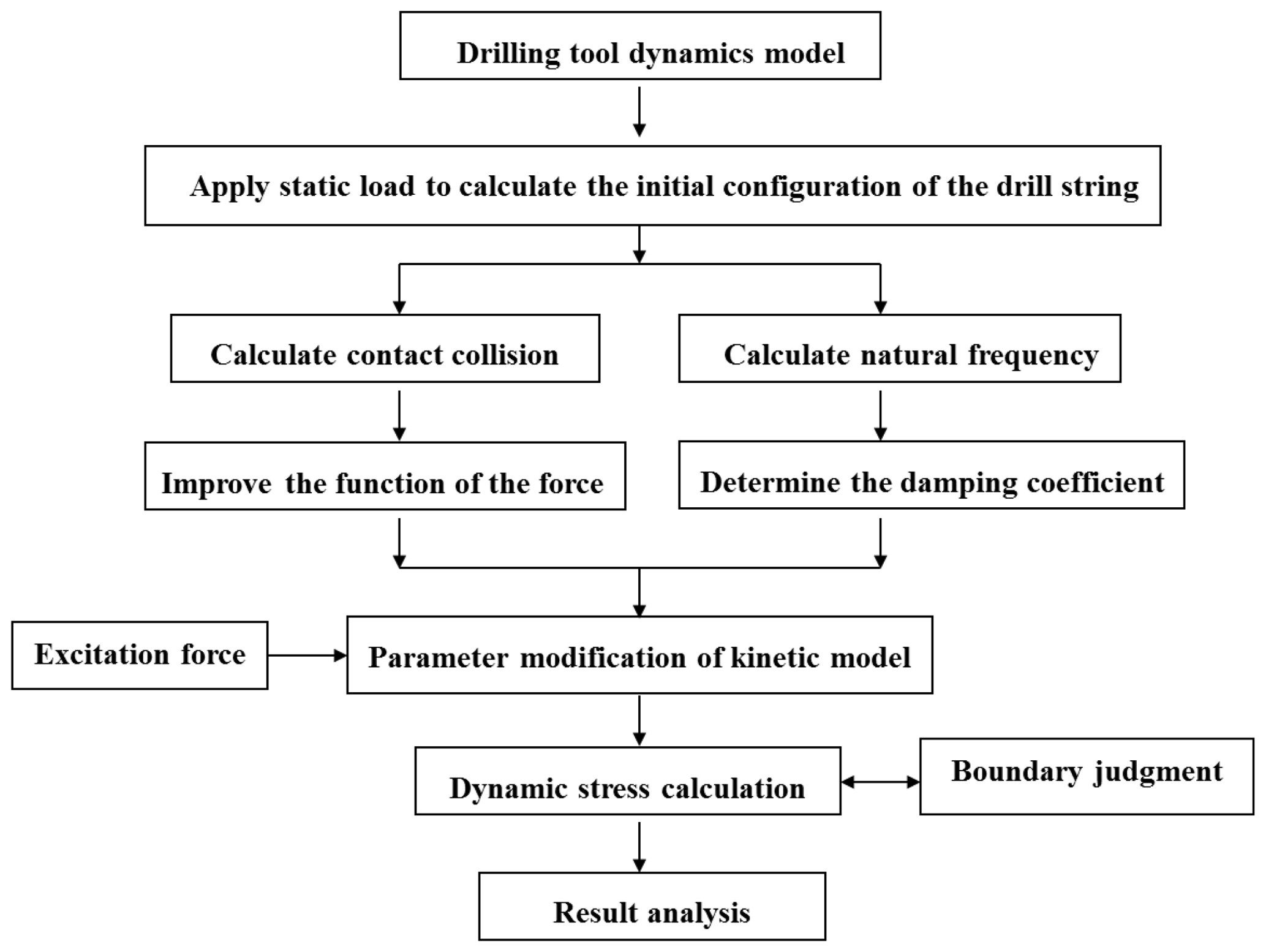
Due to the complex stress conditions of the drillstring, the drillstring is also a slender rod-shaped structure, and it must inevitably encounter the borehole wall under the excitation of external loads. The location, orientation, and manner of these contact points in the wellbore are unknown, and may be impact or continuous sliding or pure rolling, and the contact state changes with time, which is related to the rotation speed, wellbore parameters and load conditions, thus causing the dynamic boundary to be determined in the dynamic analysis of the drill string, which is more than the static boundary to be determined. It's much more complicated. The contact collision between the drillstring and the well wall causes a significant change in the relative state of the drill string and the well wall, so this process is a severe transient nonlinear process. The dynamic stress calculation process is as shown in Fig. 6 (Huang et al., 2019): firstly, establish the drill string model, define contact and apply static load, simulate the analysis of the contact process between the pipe string and the wellbore under the axial pressure, simulate the quasi-static deformation process of the drill string, and obtain the initial structure type. analyse the buckling results, get the initial displacement and import the deformed model. On the one hand, the collision calculation of the pushing process is performed to obtain the collision contact force function; on the other hand, the natural frequency of the model is calculated to determine the system damping coefficient.
3.4 Simulation Parameters
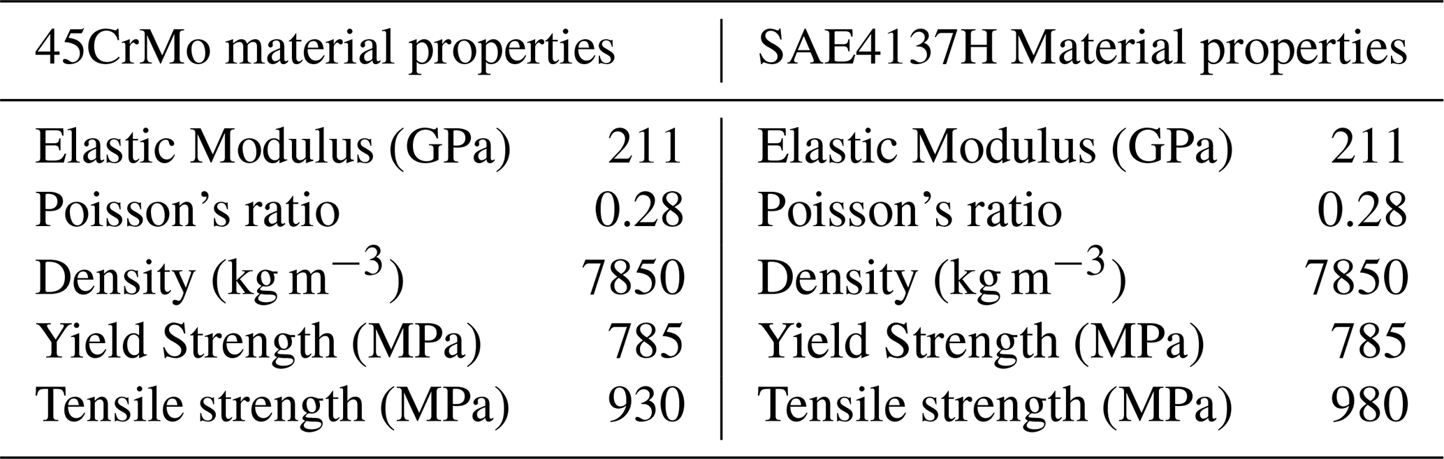
Based on the BHA design of RSS, referring to the drilling parameters during rotary steering drilling, the finite element analysis of the above BHA model is carried out using the parameters as shown in Table 2. The material properties of BHA are shown in Table 3.
In order to study the influence of the parameters of the flex sub on the deflecting ability of the RSS, the length and outer diameter of the flex sub (the actual working part of the flex sub) are selected as variables to analyse the lateral cutting force and lateral displacement of the drill bit. The pushing force is 1.5 t, the WOB is 8 t, and the rotary torque is 10 kN m.
Some basic assumptions need to be introduced before finite element analysis (Shi et al., 2013): (1) ignoring the influence of the shape of the pushing piston or rib, simplifying the pushing force to the surface force applied to the pushing surface of the rotary steerable drilling tool; (2) ignoring the effects of drilling fluid buoyancy, dynamic effects and temperature on BHA; (3) ignoring the dynamic factors in the BHA rotation process; (4) Ignoring the influence of the wall friction.
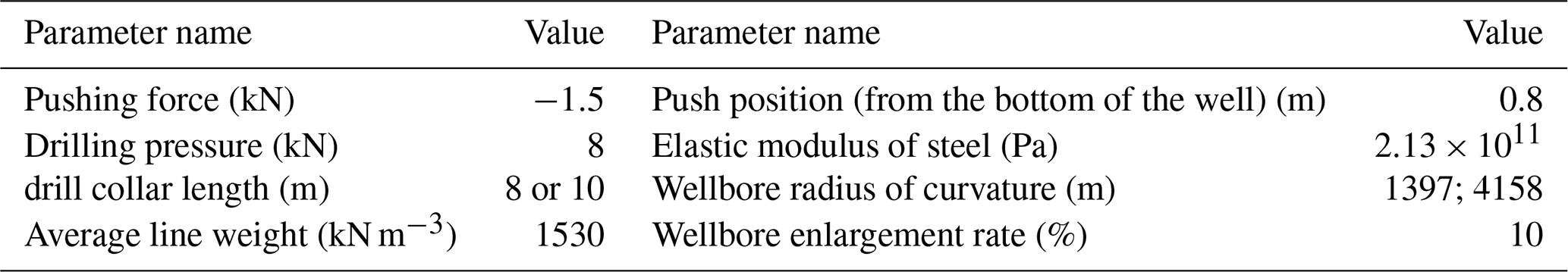
The parameters used for the analysis of the longitudinal and transverse curved continuous beams of the rotary steerable drilling BHA are shown in Table 4, the radius of curvature of the wellbore ρT=1397 m and ρT=4158 m represent the medium curvature state (curvature KT=1.25∘/30 m) and the slight curvature state (curvature KT=0.42∘/20 m). The pushing force direction is opposite to the direction shown in Fig. 3, and the equivalent drill collar length (including flex sub, drill collar, rotary steering drilling tool) is 8 and 10 m. The average line weight is obtained by dividing the total weight of the flex sub, the drill collar and the rotary steerable drilling tool by the total length.
4.1 Theoretical calculations
The longitudinal and transverse curved continuous beam method is used to analyse the mechanical properties of BHA. As shown in Figs. 7 and 8, the relationship between the lateral cutting force of the BHA and the bit angle and the deviation angle of the well when the drill collar equivalent length is 8 and 10 m respectively; In the Figs. 7a and 8a, the curvature of the wellbore where the BHA is located is in a light curvature state, in the Figs. 7b and 8b, the curvature of the wellbore is in medium curvature state. When the RSS applies the pushing force in the low direction of the wellbore, the lateral cutting force of the drill bit is positive, indicating that the lateral cutting force of the drill bit point to the high side of the wellbore. At this time, the BHA has the ability to create skew obliques.

Figure 7Affecting factors of lateral cutting force of the bit and rotation angle (the equivalent drill collar length is 8 m).
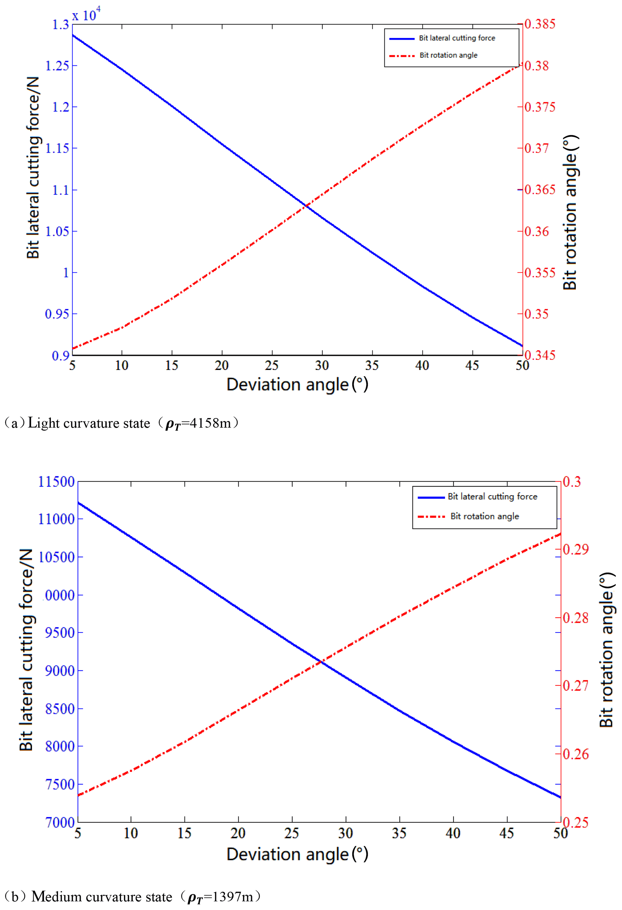
Figure 8Affecting factors of lateral cutting force of the bit and rotation angle (the equivalent drill collar length is 10 m).
Overall, as the deviation angle of the well increases, the rotation angle of the drill bit increases continuously, but when the equivalent drill collar length is 8 m and the wellbore is in a slightly curved state, when the deviation angle of the well is small, the bit rotation angle decreases with the increase of well deviation angle. Whatever the curvature of the wellbore and the equivalent drill collar length change, the lateral cutting force of the bit decreases as the deviation angle increases.
On the other hand, as the radius of curvature of the wellbore decreases, the lateral force of the drill bit and the rotation angle of the drill bit of the rotary steerable drilling BHA are gradually reduced, and the ability to create the inclination is reduced. With the increase of the length of the equivalent drill collar, the lateral force of the drill bit and the rotation angle of the drill bit of the rotary guide drilling have a small increase, indicating that a long drill collar can increase deviation ability of the RSS.
4.2 Simulation analysis of statics
4.2.1 Effect of flex-sub to BHA using RSS
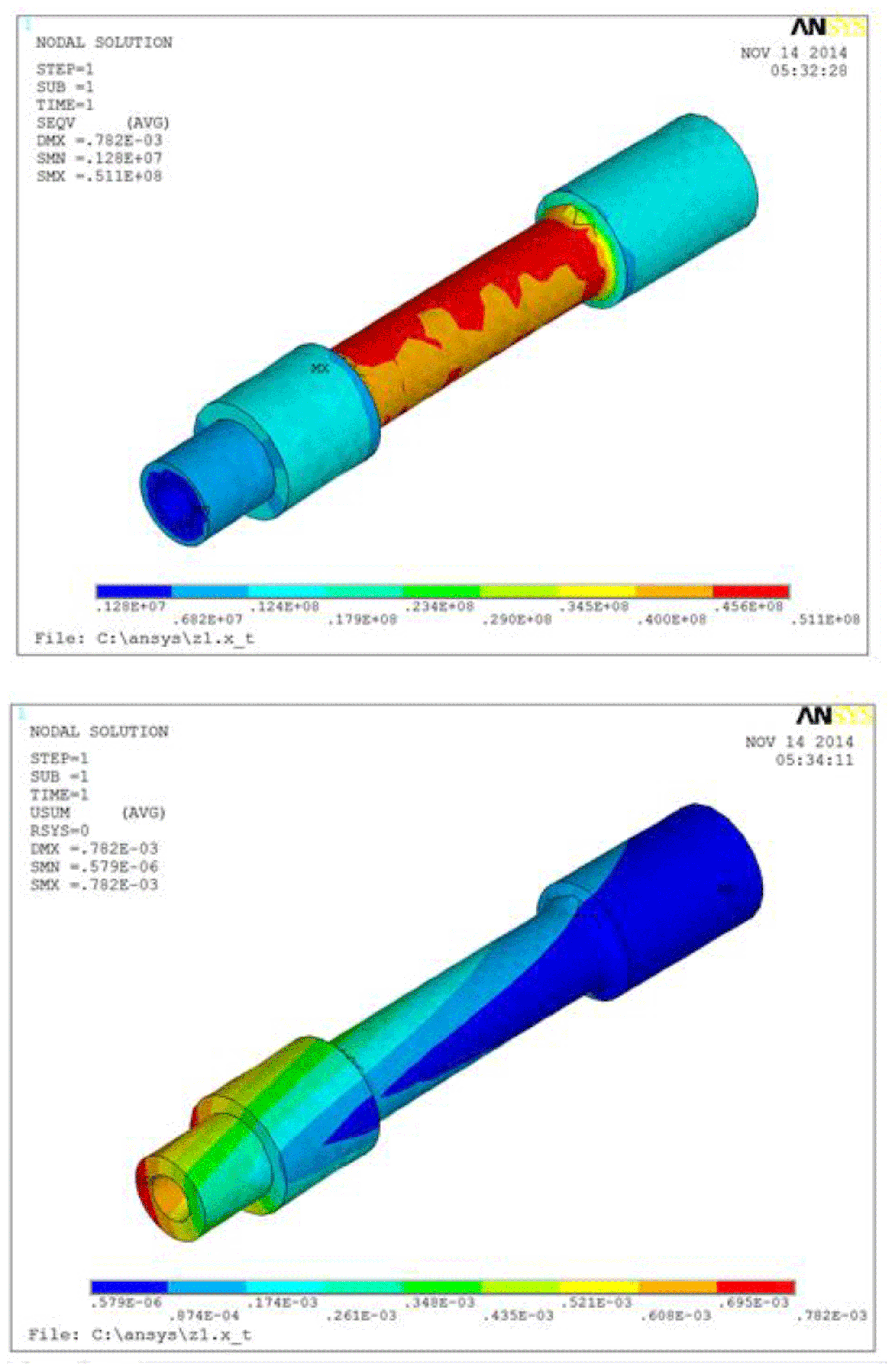
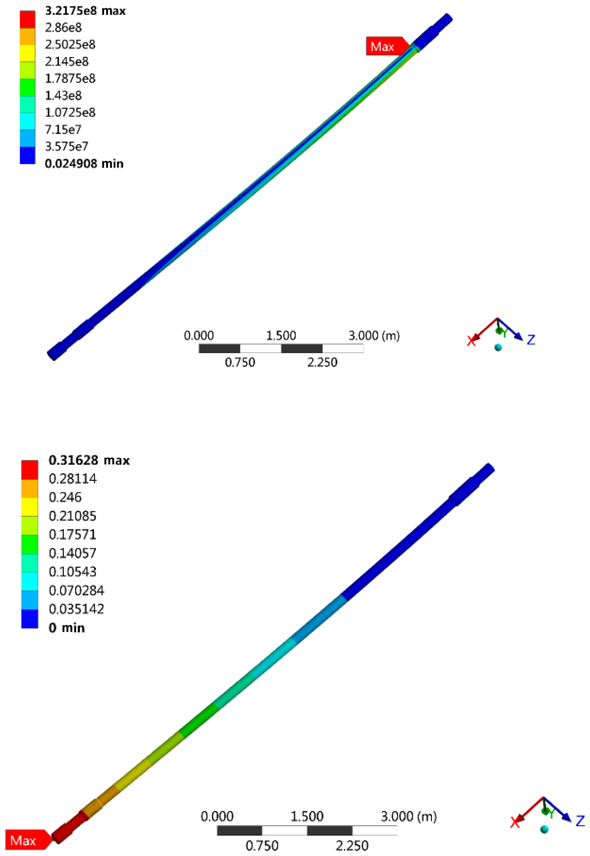
The design of experiments (DOE) method in the ANSYS Work-bench was employed to create a design space and Standard Response Surface-Full 2nd order polynomial model was used to study the influence of design variables on the RSS efficiency. After the flex sub is added to BHA, the maximum stress increases from 3.22×10⁸ to 8.01×10⁸ Pa, which is up to 148.76 %, and the maximum stress appears on the flex sub, indicating that the flex sub is the weak part of BHA. In order to ensure the safety of the drilling process, the design parameters of the flex sub need to be further analysed to provide a basis for the design of the flex sub. The distribution of stress and deformation of flexible sub as design in this paper are shown in Fig. 9. It can be seen that stress and deformation meet safety requirements.
As shown in Figs. 10 and 11, the stress cloud map and the total deformation cloud map before and after the installation of the flex sub respectively. It can be seen that after adding flex sub to the BHA of the RSS, the maximum displacement of the drill bit increases from 316.3 to 488.25 mm and the increase of displacement is up to 54.36 % when the BHA is in the free state (fixed stabilizer only). As a result, the rotation angle of the drill bit can be significantly increased, and the deviation ability of the RSS is further greatly improved. Therefore, in the rotary steering drilling process, the BHA design with flex sub should be selected.
4.2.2 Effect of the outer diameter of the flex-sub
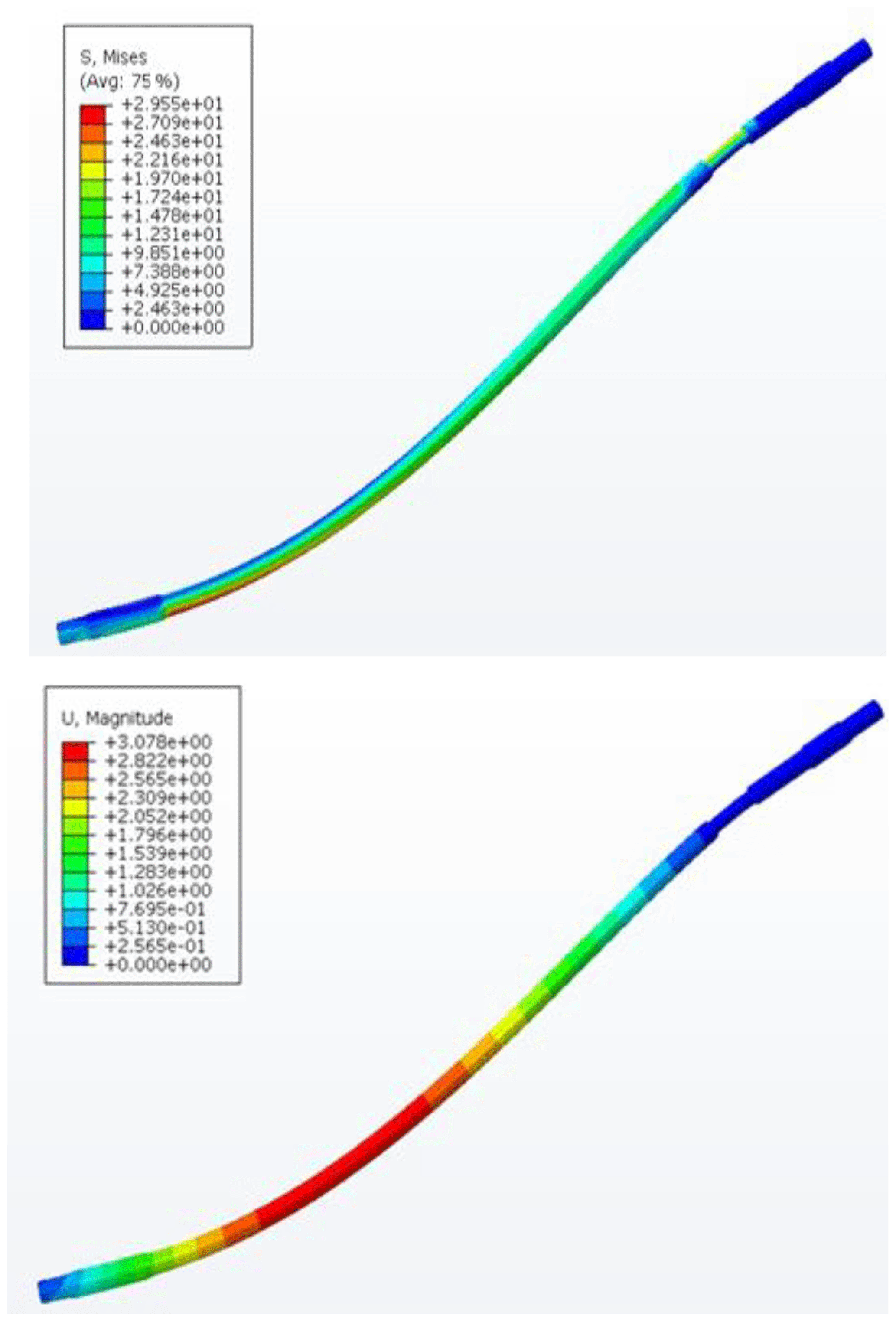
From simulation analysis, we found that the maximum stress is always at the root of the flex-sub, and the maximum displacement is on the side of the drill bit. When the length of the flex-sub is fixed (the length of the flex-sub is 800 mm in this paper), the maximum stress, displacement and lateral force of drill bit of different flex sub outer diameter are shown in Fig. 12. With the increase of the outer diameter of the flex sub, the maximum stress and the maximum displacement gradually decrease, and the maximum stress and the maximum displacement decrease by 66.04 % and 35.03 %, respectively, indicating that the increase of the flex-sub stiffness helps to reduce the maximum stress, but reducing the steering deflecting capability of RSS. With the increase of the stiffness of the flex sub, the lateral cutting force of the drill bit decreases slightly. The numerical value of the lateral cutting force of the bit is basically the same as that of the drill collar 10 m above and the borehole is slightly bent, indicating that the simulation is reasonable.
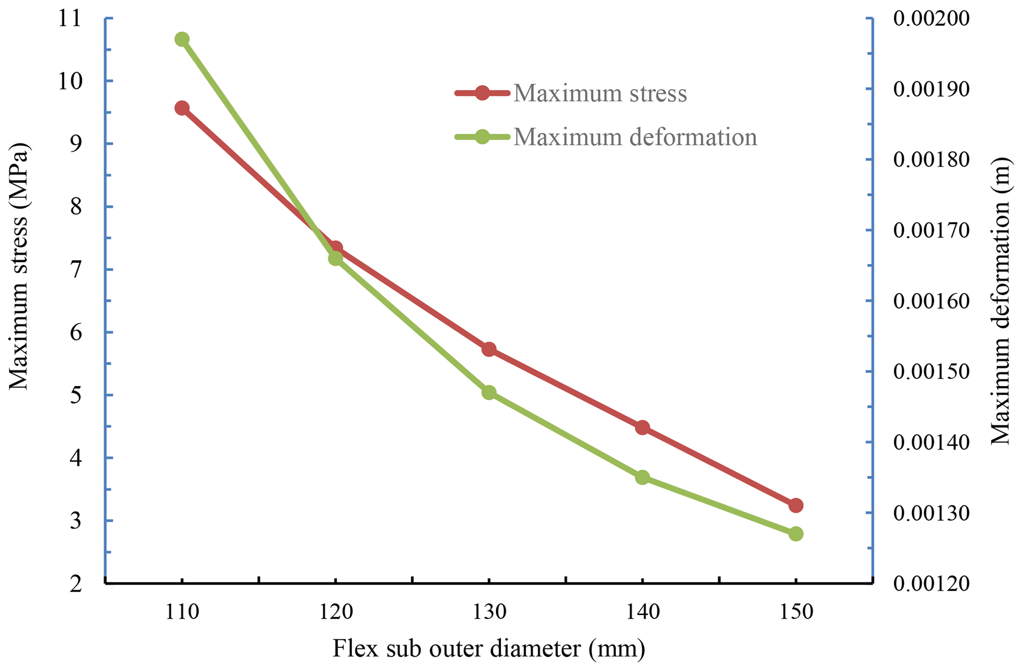
Figure 12The variation of stress and maximum displacement of BHA with the outer diameter of flex sub (800 mm length).
4.2.3 Effect of length of flex-sub
When the outer diameter of the flex sub is fixed, the maximum stress, displacement and lateral force of different flex sub outer diameter are shown in Fig. 13. With the increase of the length of the flex sub, the maximum stress and maximum displacement of the BHA are improved. When the length of the flex sub is increased from 600 to 1000 mm, the maximum stress increase is only 1.23 %, indicating that the increase of flex sub length has little effect on the reliability of flex sub. However, with the increase of the length of the flex sub, the maximum displacement increases from 1.38 to 1.58 mm, which is up to 14.49 %, indicating that as the length of the flex sub increases, the torsion resistance of the drill tool gradually decreases, especially in the case of high torque drilling (Carpenter, 2013).

Figure 13The variation of stress and maximum displacement of BHA with the length of flex sub (130 mm outer diameter).
The excessive length of the flex sub will reduce the life of the BHA. The lateral cutting force of the bit increases with the length of the flex sub, which is consistent with the trend in the above analysis. However, the increase of the lateral cutting force of the bit becomes smaller after the flex sub is added, and the influence of bit lateral cutting force is obviously reduced compared with that of conventional drill collar.
Considering the condition of downhole vibration in drilling process, BHA is in a state of alternating stress (Besaisow and Payne, 1988; Samuel and Yao, 2013). In order to ensure the safety of the drilling, the fatigue strength check of the flex sub is required. For conventional metal materials, the fatigue limit is generally 20 % to 30 % of the yield strength, and then the fatigue of flex sub is calculated according to 20 % of the yield strength. The safety factor is 2.5, and the upper limit of stress of the flex sub is 6.28×10⁷ Pa. Since the length of the flex sub has little effect on the maximum stress, the maximum stress is mainly determined by the outer diameter of the flex sub. As is shown in Fig. 11, when the outer diameter of the flex sub is greater than 123 mm, the safety of BHA can be ensured during use. In order to obtain the lateral cutting force of the drill bit as big as possible, the flex sub should be used as long as possible. But the excessive length of the flex sub will deteriorate the anti-twist performance of the entire BHA. In order to ensure that BHA has certain anti-torsion performance, the maximum torsional displacement of BHA should not exceed 1.5 mm. The length of flex sub is not more than 875 mm, which can meet the application requirements. In the actual drilling process, the required flex subs are as close as possible to the existing sizes of drillstring and drill collar. At the same time, with reference to the action law of the above flex sub, a flex sub with 127 mm diameter and 812 mm length is designed as a BHA assembly for rotary steerable drilling of 216 mm diameter borehole.
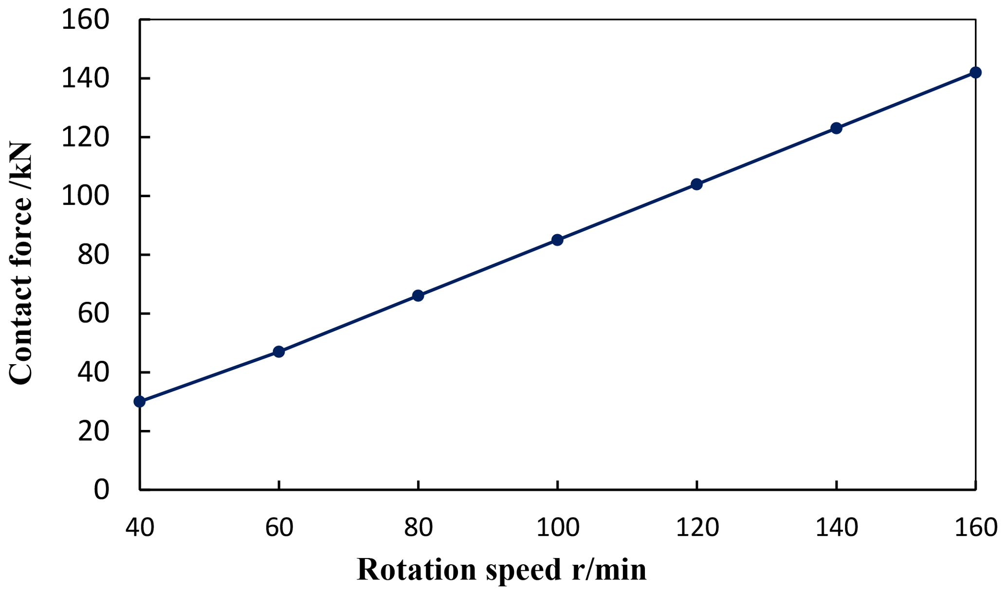
The drillstring rotates at different speeds and hits the well wall at the same time. When the drillstring rotates, the rotating guide pads will collide with the borehole during the extension process. The collision speed is related to the acceleration and the radius of the well wall. The radius of the shaft wall is 108 mm, and the collision linear velocity is expressed as v=ωR, wherein ω is rotation angular velocity of drillstring, R is the borehole radius. The simulation shows that the collision contact force of the RSS tool and the shaft wall changes with the rotation speed as shown in Fig. 14. It can be seen that with the increase of the rotation speed, the peak of the contact force becomes larger, almost in line with the linear relationship.
When the drillstring is at different speeds, study its dynamic characteristics. Mainly from the following two aspects.
5.1 Lateral cutting force of the drill bit
When the rotation speed is 60, 100 and 140 r min−1, the simulation process is shown in Fig. 6. The change of lateral force of the drill bit in different periods is shown in Fig. 15. When the rotation speed is 140 r min−1, the lateral force is maximum at 6.1 s is about 45 kN. When the speed is 60 r min−1, the maximum lateral force is 25 kN. At different speeds, as time increases, the lateral force fluctuates around 20 kN.
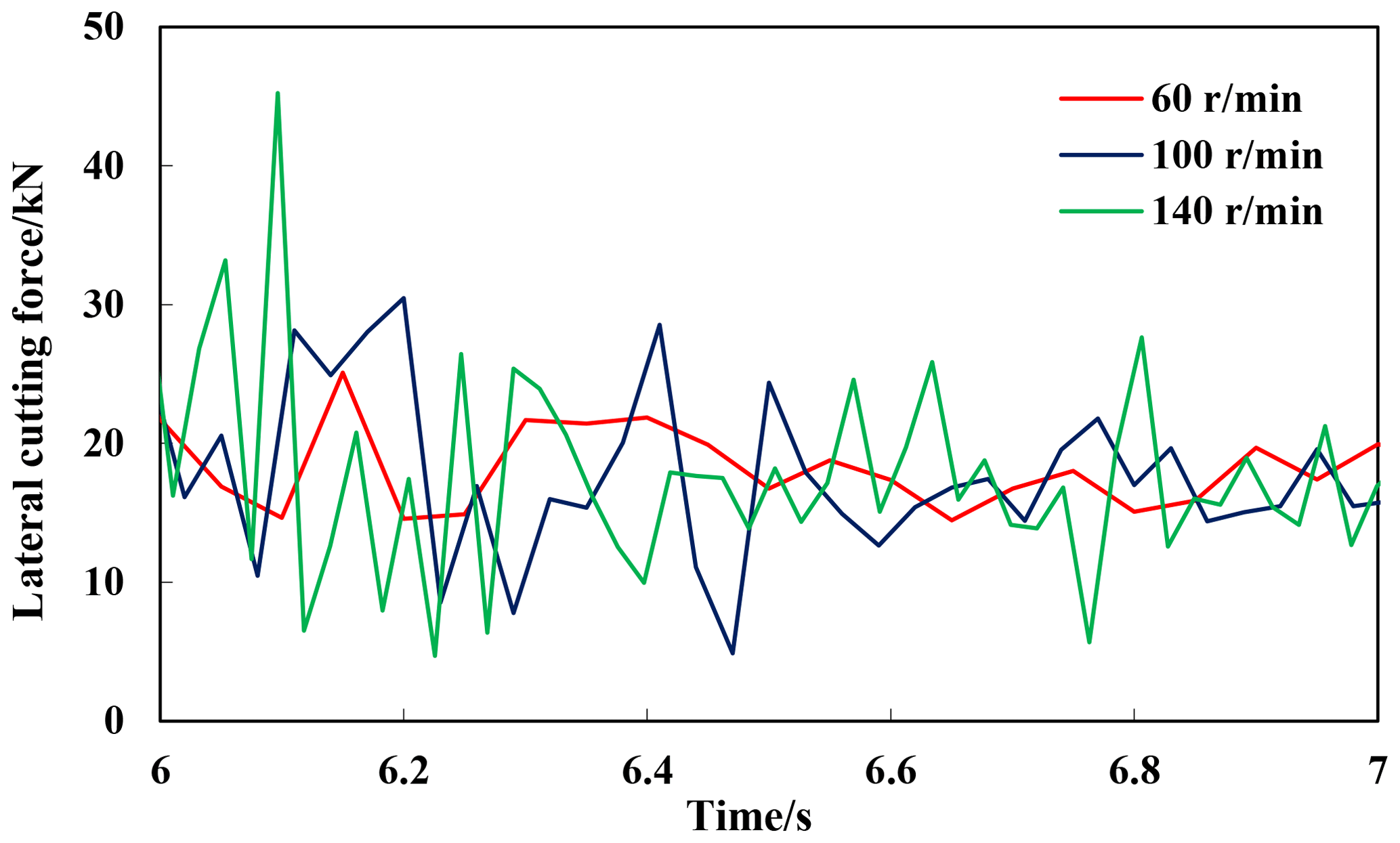
The variable cutting forces values (Fig. 15) will lead to the torsional vibrations appearing. As shown in Fig. 16, the rotation speed of the drill bit fluctuates.
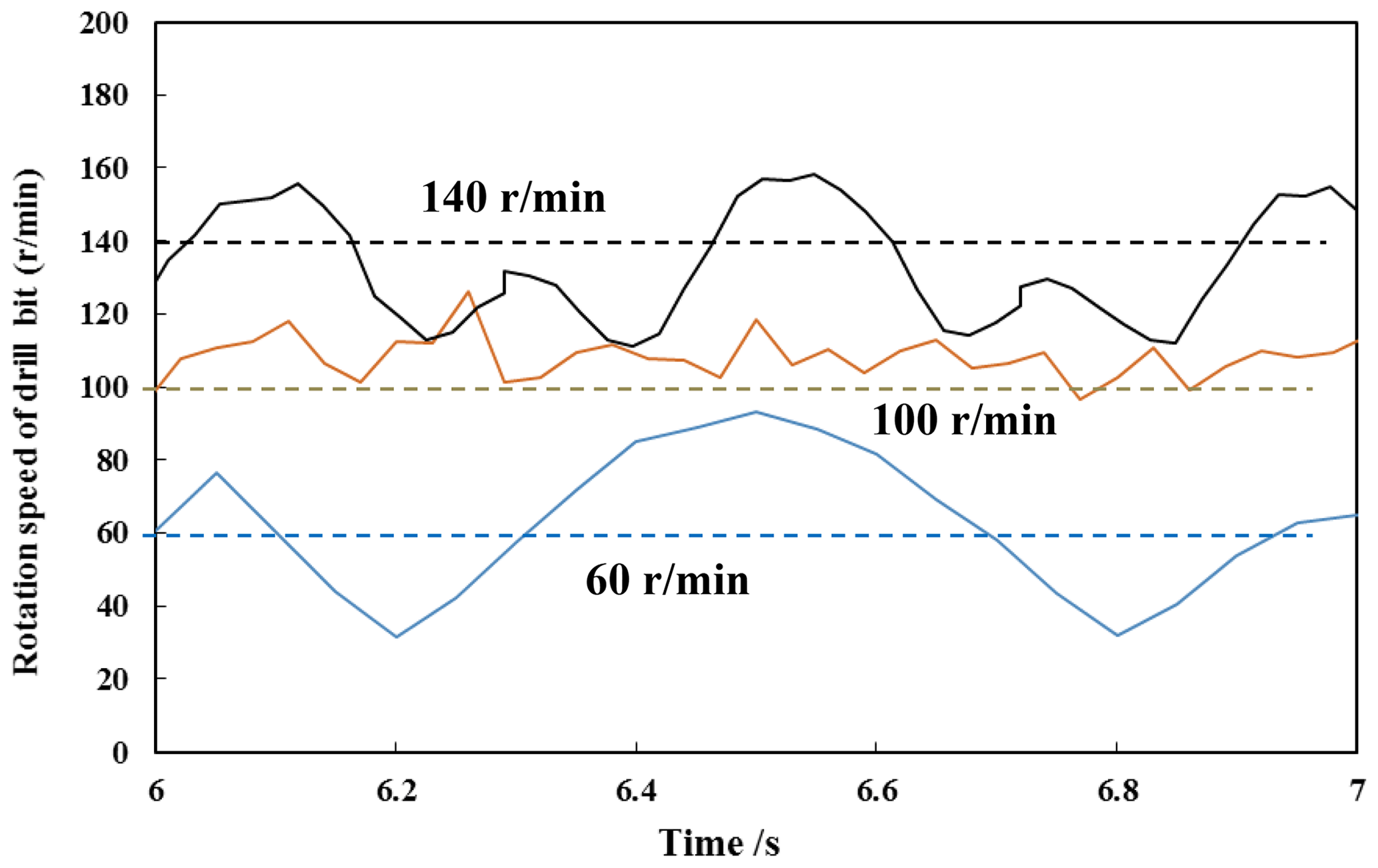
When the RSS works, it will generate a pushing force to push against the wellbore, the pads pushed to the borehole by internal and external drilling fluid differential pressure. After a period of time, it is turned off, the next one is turned on, and in this way the full-rotation dynamic correction is realized. The generated lateral force of the drill bit changed the drilling trajectory, but at the same time it also brought about aggravation of stick-slip vibration, as shown in Fig. 16.
5.2 Alternating stress
During the RSS drilling process, due to the constant pushing of the ribs against the well wall, a changing dynamic stress was generated, Fig. 17 shows the change of the maximum stress point in different periods when the speed is 60, 100 and 140 r min−1. The maximum stress varies with the speed. When the rotation speed is 140 r min−1, the peak stress is about 65 MPa. When the rotation speed is 100 r min−1, the peak stress is the smallest, which is 52 MPa.
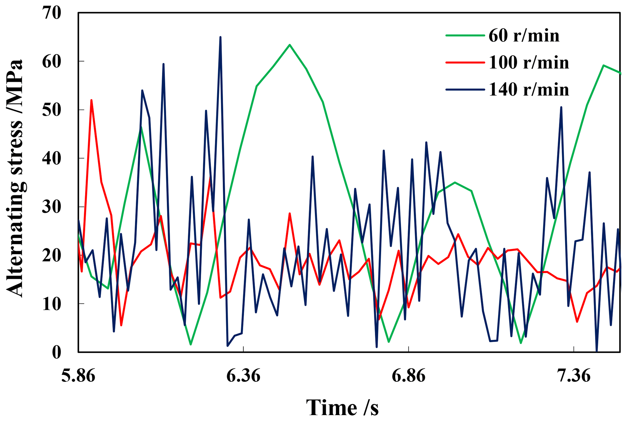
For different drilling tool combinations, different boundary conditions are established, the collision contact force function and the damping coefficient are imported into the model, and combined with other functions such as speed, torque, gravity, buoyancy, and thrust force, then the dynamic stress is obtained. The research results show that the lateral force gradually fluctuates around a value; the position of the maximum stress point at different speeds is different, and the change period and peak value are different.
Through the theoretical calculation and finite element analysis of RSS with flex-sub for rotary steering drilling, the following conclusions can be obtained:
-
Analysis of the longitudinal and transverse bending beams of BHA for RSS shows that the larger deviation angle of the well is, the more difficult to deflect is, and the lower the deflecting efficiency of the rotary steerable tool under certain pushing force is. With the lateral pushing force of the push-to-bit RSS, the longer drill collar can obtain a larger bit lateral cutting force and bit rotation angle.
-
The finite element analysis of RSS show that steering drilling capability of the RSS increases after installing the flex sub, but the design parameters of the flex sub directly affect BHA's deflecting performance and reliability.
-
Analysis of the effect of flex sub of different design parameters shows that as the outer diameter of the flex sub increases, the stiffness of the BHA increases and the maximum stress of the BHA decreases. As the length of flex sub increases, the lateral cutting force of the drill bit increases, which causes a decrease in the torsional resistance of the BHA. Through comparative analysis and strength check, a flex sub with a diameter of 127 mm and length of 812 mm is selected for a 216 mm diameter borehole rotary steerable drilling tool.
-
The lateral cutting force gradually fluctuates around a value; the position of the maximum stress point is different at different speeds, and the period of change and the peak value are different.
Additionally, in this paper we analysis of the dynamic model of the rotary steerable drilling tool with a single stabilizer and the influence of flex sub on the guiding drilling performance, it has reference value for flexible sub design in rotary steer drilling. This is a basic analysis, so more assumptions are used, the effect of temperature has not been taken into account in this article and the relationship between the lateral force and the relative inclination of the bit on the borehole axis (Pastusek et al., 2005) is not considered. Further improvements on the dynamics and model experiments will be carried out in future work.
All data, models, and codes generated or used during the study are available from the corresponding author upon request.
JW, QX, LL, BL and FL analyzed the data and developed the model; LH and JW performed the experiments; QX, FL and JW prepared the figures. QX, LL, JW and FL wrote and edited the manuscript.
The authors declare that they have no conflict of interest.
This research has been supported by the Natural Science Foundation of China (grant no. 51704264), the National Key R&D Program of China (grant no. 2016YFE0202200), and the Fundamental Research Funds for the Central Universities (grant no. 2-9-2018-096).
This paper was edited by Guimin Chen and reviewed by four anonymous referees.
Aadnoy, B. S., Fazaelizadeh, M., and Hareland, G.: A 3D analytical model for well bores friction, J. Can. Petrol. Technol., 10, 25–36, https://doi.org/10.2118/141515-pa, 2010.
Bailey, J. J. and Finnie, I.: An analytical study of drillstring vibration, ASME J. Eng. Ind., 2, 1960, 122–128, 1960.
Barr, J. D., Clegg, J. M., and Motion, W. C.: Steerable rotary drilling systems, United States Patent 6089332, 2000.
Besaisow, A. A. and Payne, M. L.: A Study of Excitation Mechanisms and Resonances Inducing Bottomhole-Assembly Vibrations, SPE Drilling Engineering, 3, 93–101, https://doi.org/10.2118/15560-pa, 1988.
Brands, S. and Lowdon, R.: Scaled Tortuosity Index: Quantification of Borehole Undulations in terms of Hole Curvature, Clearance and Pipe Stiffness, IADC/SPE Drilling Conference & Exhibition, Society of Petroleum Engineers, San Diego, California, USA, 2012.
Carpenter, C.: Torsional Dynamics and Point-the-Bit Rotary-Steerable Systems, J. Petrol. Technol., 65, 111–114, https://doi.org/10.2118/1213-0111-jpt, 2013.
Carpenter, C.: Rotary-Steerable Tool Brings Cost-Effective Performance to High-Volume Drilling, J. Petrol. Technol., 66, 111–113, https://doi.org/10.2118/1214-0111-jpt, 2014.
Dareing, D. W.: Drill collar length is a major factor in vibration control, J. Petrol. Technol., 4, 637–644, https://doi.org/10.2118/11228-pa, 1984a.
Dareing, D. W.: Guidelines for controlling drillstring vibrations, J. Energ. Resour.-ASME, 2, 272–277, 1984b.
Dunayevsky, V., Abbassian, F., and Judzis, A.: Dynamic stability of drillstrings under fluctuating weight on bit, SPE Drill Completion, 8, 84–92, 1993.
Di, Q., Wang, M., Hu, Y., Zhao, Y., Zhu, W., and Wang, W.: Effect of flex sub's position on bottom hole assembly with rotary steering tool, Journal of China University of Petroleum (Natural Science Edition), 36, 84–88, 2012.
Elsayed, M. A. and Phung, C. C.: Modeling of drillstrings, in: Proceedings of the 24th ASME International Conference on Offshore Mechanics and Arctic Engineering (OMAE), Halkidiki, Greece, 2005.
Greenwood, J. A.: Directional Control and Rathole Elimination While Underreaming Depleted Formations with a Rotary-Steerable System, SPE Drill. Completion, SPE-187098-PA, 33, 1–7, https://doi.org/10.2118/187098-pa, 2018.
Huang, L., Xue, Q., Liu, B., Yang, C., Wang, R., and Han, L.: Dynamic Reliability Analysis of Rotary Steering Drilling System, Mech. Sci., 10, 79–90, https://doi.org/10.5194/ms-10-79-2019, 2019.
Huang, W., Lou, Y., Xu, H., Wang, Q., and Chen, Y.: Force and influencing factors analysis for bottom hole assembly with two stabilizers and one bend, Research Journal of Applied Sciences Engineering & Technology, 6, 3811–3814, https://doi.org/10.19026/rjaset.6.3595, 2013.
Kreisle, L. F. and Vance, J. M.: Mathematical analysis of the effect of shock sub on the longitudinal vibrations of an oil well drillstring, Soc. Petrol. Eng. J., 4, 349–356, https://doi.org/10.2118/2778-pa, 1970.
Liu, X., Vlajic, N., Long, X., Meng, G., and Balachandran, B.: Nonlinear motions of a flexible rotor with a drill bit: stick-slip and delay effects, Nonlinear Dynam., 72, 61–77, https://doi.org/10.1007/s11071-012-0690-x, 2013.
Liu, X., Vlajic, N., Long, X., Meng, G., and Balachandran, B.: Coupled axial-torsional dynamics in rotary drilling with state-dependent delay: stability and control, Nonlinear Dynam., 78, 1891–1906, https://doi.org/10.1007/s11071-014-1567-y, 2014.
Lubinski, A.: Dynamic loading of drill pipe during tripping, J. Petrol. Technol., 8, 975–983, https://doi.org/10.2118/17211-pa, 1988.
Melakhessou, H., Berlioz, A., and Ferraris, G.: A nonlinear well-drillstring interaction model, J. Vibr. Acoust., 12546–12552, 2003.
Panayirci, H. M., Brands, S., and Houette, O.: Selection of optimum bottom hole assembly configuration using steering prediction modeling, J. Nat. Gas Sci. Eng., 27, 757–762, https://doi.org/10.1016/j.jngse.2015.09.018, 2015.
Pastusek, P., Brackin, V., and Lutes, P.: A fundamental model for prediction of hole curvature and build rates with steerable bottomhole assemblies, in: SPE Annual Technical Conference and Exhibition, SPE 95546, Dallas, TX, https://doi.org/10.2523/95546-ms, 2005.
Rattanawangcharoen, N., Bai, H., and Shah, A. H.: A 3D cylindrical finite element model for thick curved beam stress analysis, Int. J. Numer. Meth. Eng., 59, 511–531, 2004.
Ritto, T. G., Escalante, M. R., Sampaio, R., and Rosales, M. B.: Drillstring horizontal dynamics with uncertainty on the frictional force, J. Sound Vib., 332, 145–153, https://doi.org/10.1016/j.jsv.2012.08.007, 2013.
Samuel, R. and Yao, D.: DrillString Vibration with Hole-Enlarging Tools: Analysis and Avoidance, J. Energ. Resour.-ASME, 135, 032904, https://doi.org/10.1115/1.4023330, 2013.
Santos, J., Priimenko, V., and Sugiura, J.: Modeling of BHA dynamic behaviors BHA, Journal of Petroleum Exploration and Production Technology, 4, 97–104, https://doi.org/10.1007/s13202-013-0093-7, 2014.
Sarker, M., Rideout, D. G., and Butt, S. D.: Dynamic model for 3D motions of a horizontal oil well BHA with wellbore stick-slip whirl interaction, J. Petrol. Sci. Eng., 157, 482–506, https://doi.org/10.1016/j.petrol.2017.07.025, 2017.
Shi, M., Srisupattarawanit, T., Schiefer, F., and Ostermeyer, G.: On the Wellbore Contact of Drill Strings in a Finite Element Model, PAMM, 13, 109–110, https://doi.org/10.1002/pamm.201310050, 2013.
Sloboda, A. and Honarmandi, P.: Generalized Elasticity Method for Curved Beam Stress Analysis: Analytical and Numerical Comparisons for a Lifting Hook, Mech. Based Des. Struct., 35, 319–332, 2007.
Su, Y., Tan, X., and Chen, Z.: Equivalent Ioading method for solving beam-column with initial bending and its application in drilling engineering, J. Mechanics in Engineering, 26, 42–44, 2004.
Verdam, F. J. and Schouten, R.: Modeling and Analysis of Drillstring Vibration in Riserless Environment, J. Energ. Resour.-ASME, 135, 013101, https://doi.org/10.1115/1.4007691, 2013.
Warren, T.: Rotary steerable technology conclusion: implementation issues concern operators, Oil Gas J., 96, 23–24, 1998.
Wilson, J. K. and Heisig, G.: Nonlinear Drillstring-Dynamics Modeling of Induced Vibrations in Unconventional Horizontals, SPE Drill. Completion, 30, SPE-173049-PA, https://doi.org/10.2118/173049-pa, 2015.
Xue, Q., Leung, H., Wang, R., Liu, B., Huang, L. and Guo, S.: The chaotic dynamics of drilling, Nonlinear Dynam., 83, 1–16, 2016.
Xue, Q., Leung, H., Huang, L., Zhang, R., Liu, B., Wang, J., and Li, L.: Modeling of torsional oscillation of drillstring dynamics, Nonlinear Dynam., 96, 267–283, https://doi.org/10.1007/s11071-019-04789-x, 2019.