the Creative Commons Attribution 4.0 License.
the Creative Commons Attribution 4.0 License.
 | 03 Jun 2020
Study on dynamic characteristics of underwater pressure compensator considering nonlinearity
Songyu Li
Xinguang Du
Luyao Zhang
Ken Chen
Shuai Wang
The external pressure is the biggest problem faced by underwater hydraulic systems. The strength and sealing ability of the structure are facing enormous challenges. For this problem, the common solution is to use pressure compensation technology. The pressure of the seawater is transmitted to the inside of the hydraulic system through a pressure compensator, which equalizes the return pressure of the hydraulic system and the seawater pressure. The structure of the compensation system, the volume and dynamic characteristics of the compensator, and the compensation failure caused by hydraulic oil leakage will all affect the normal operation of the underwater equipment. Therefore, it is necessary to study the pressure compensation system. This paper analyzes the pressure characteristics of the rubber-bellows type compensator. The dynamic characteristic equation of the pressure is established. Due to the strong nonlinear nature of rubber, the finite element method is used to simulate the deformation process of the rubber-bellows type pressure compensator. The relationship between the volume variation and the spring displacement of the rubber-bellows type pressure compensator is calculated by FE simulation. The relationship is brought into the theoretical equation result to obtain the pressure characteristics of the compensator. Through the control variable method, the influence of damping, total mass, effective area and spring stiffness on the internal pressure of the compensator is obtained. According to the analysis result, the damping ratio should be appropriately increased to reduce the overshoot of pressure fluctuations in the design. Since the damping is difficult to control, the total mass of the end cap, the guide post, the rubber bellows and the spring can be minimized. It also reduces the quality of the equipment. The spring stiffness and effective area have a significant influence on the steady-state pressure. A softer spring should be used and the effective area should be increased as much as possible to reduce the final steady-state pressure.
- Article
(5871 KB) - Full-text XML
- BibTeX
- EndNote


With the exploration of marine resources by human beings, some tasks like marine surveying and monitoring develop from shallow sea to deep sea. the requirements for the depth and reliability of underwater robots are also increasing. The requirements for the depth and reliability of underwater robots are also increasing (Whitcomb, 2000). Due to some advantages like higher energy density and achieving stepless speed regulation much easier compared to electricity, the hydraulic power is generally used in heavy-load underwater vehicles (Bruno et al., 2015; Yang et al., 2017). Underwater pressure has an obvious influence on the actuators, control components, sealing components, oil and reliability of the hydraulic system. There are three key issues to be solved during underwater instruments development: sealing problems, strength problems and corrosion problems (Wang et al., 2005). The pressure varies with the depth of the working water. Some measures must be taken to reduce the impact of external seawater pressure on the hydraulic system. In early underwater hydraulic systems, the power source, control unit and actuator were respectively installed in pressure resistant vessels (Greeneri, 1971). It will enlarge the total mass of the underwater equipment by just increasing the pressure resistance of the pressure vessel in the deep water of several kilometers. It can also cause the useful signals of some sensors (such as force sensors) to be overwhelmed and even damage some sensitive components (such as elastomers). Thus the pressure compensation is the most commonly used method at home and abroad. It meets the requirements of small mass, low energy consumption and high precision of underwater instruments (Torma and Szepesvári, 2006). In the pressure compensated hydraulic system, the system pressure is based on the external water pressure. The land hydraulic system can be easily extended to underwater without considering the effects of water pressure (Li, 2005).
The pressure compensator is the key equipment of the pressure compensation system. There are several different forms of compensators, such as capsule type, diaphragm type, bellows type, etc., as shown in Fig. 1 (Wang, 2009; He et al., 2007). For the capsule type pressure compensator, the radial deformation resistance is smaller than the axial deformation resistance due to its shape and the capsule surface mainly deformed in a radial direction. But the spring is difficult to be set in this deformation mode. Although the piston can be used to force the capsule to deform axially, the total deformation in a single axial direction is much smaller than that in a natural shape and the compensation capacity is small. At the same time, due to the nonlinear relationship between the axial deformation and the driving force of the capsule, the compensation pressure will be greatly affected (Cao et al., 2011). Due to the defect mentioned above, the capsule type pressure compensator is not commonly used. A rubber diaphragm is used as the flexible component in the diaphragm pressure compensator. This type of compensator is usually used for the variable volume chamber (Tian et al., 2019). It is usually designed to be integrated with the oil tank. The structure makes it easy to set springs. The rolling diaphragm pressure compensator is commonly used. There are several advantages. The rolling diaphragm move in two directions, and the stroke reaches 70 % of the diaphragm height, which is impossible for other diaphragm types. The stroke of the rolling diaphragm is usually 3–7 times that of the disc or wave diaphragm. The rolling diaphragm has the deformation resistance as small as possible because of its shape and material, and remains constant within the effective stroke range. The frictional resistance is also small because the rolling diaphragm is in a rolling state during movement. The bellows type pressure compensator uses retractable rubber bellows as the elastic element. Since the amount of axial deformation is nonlinearly related to the driving force, it will have a large influence on the compensation pressure. The bellows type pressure compensator uses retractable rubber bellows as the flexible component. Since the axial deformation is nonlinearly related to the driving force, it will have a obvious influence on the compensation pressure. The advantage is that the compensation capacity of this type is much bigger than that of other compensator due to the large amount of expansion and contraction of the rubber bellows.
The pressure compensation process is divided into static and dynamic pressure compensation depending on the application location (Gu et al., 2013). Since the total amount of oil in the valve vessel is constant, only the oil compressed by seawater pressure needs to be compensated and that is static pressure compensation. When a hydraulic cylinder works in the hydraulic system, the amount of oil in the hydraulic tank will be varied. At this time, the pressure compensator should also supply this part of the oil and that is dynamic pressure compensation. When the hydraulic cylinder works, it will cause a drastic variation of the compensating pressure. If the compensating pressure is too large, it may break the elastic component of the compensator. If the compensating pressure is too small, it may cause leakage of seawater. Therefore, it is necessary for the pressure compensator. Therefore, it is necessary to study the dynamic characteristics of the pressure compensator to ensure that the fluctuation of the compensation pressure is within a reasonable range. Meng et al. (2000) studied the pressure compensator for underwater hydraulic power unit and proposed a method for calculating static pressure compensation capacity. Zhang et al. (2007) studied the adaptive pressure compensation technology of underwater robots, and derived the static and dynamic characteristic equations of piston pressure compensators. Wang and Chen (2014a, b) conducted a detailed study on the dynamic characteristics of rolling diaphragm pressure compensators for underwater hydraulic systems. Through the simulation analysis, the corresponding variations of the compensating pressure are obtained when the hydraulic cylinder inputs different types of signals such as impulse, step and sine, and it is verified by the test method. On the basis of the dynamic characteristics of pressure compensator, Liu et al. (2016) proposed a design method of rolling diaphragm pressure compensator and verified the method through experiments. Hu et al. (2018) used AMESim software to build a hydraulic system model with a pressure compensator, and studied the effects of multiple compensators on pressure fluctuations. The rolling diaphragm pressure compensator was mainly studied in the above research on the pressure characteristics. At the same time, the influence of the compensator volume variation on the compensating pressure in dynamic compensation is not considered.
In this paper, the pressure characteristics of the bellows type pressure compensator are analyzed. Since the volume of the rubber bellows vary greatly during the dynamic compensation process, the variation has a significant influence on the internal pressure of the compensator and cannot be ignored. Since the rubber material has strong nonlinear characteristics, the FEM is used to obtain the relationship between the volume variation of the rubber bellows and the spring displacement of the pressure compensator. This relationship is brought into the analytical model and the dynamic pressure characteristics of rubber bellows type pressure characteristics are gotten. Through the control variable method, the influence of different design parameters on the dynamic characteristics of the pressure compensator is studied. The key parameters and influence laws affecting the internal pressure of the compensator are determined.
Figure 2 shows a typical rubber bellows type pressure compensator. The bellows are made with a reinforced rubber sheet. There are metal end caps at top and bottom of the bellows. The bottom end cap is connected to the interior of the hydraulic system via a hydraulic line connection. The inside of the bellows is filled with hydraulic oil. Similar to the rolling diaphragm pressure compensator, several springs are also mounted between the upper and lower end caps. The springs can be installed inside or outside of the bellows, and the guide column is arranged at the axis to guide the spring. The springs are installed with a certain pre-tension to prevent seawater leakage. When the external pressure varies, the rubber bellows are compressed and the volume of oil chamber is reduced. The pressure is then transmitted to the inside of the hydraulic system with the hydraulic oil.
The mathematical model of the rubber bellows type pressure compensator will be established first to study the dynamic characteristics. Figure 2 shows the state of the pressure compensator at a transient equilibrium time. When the pressure of the oil chamber varies Δpi, the volume variation ΔV of the hydraulic oil can be expressed as
where E is the bulk modulus of hydraulic oil; V(y) is the oil chamber volume in the compensator and it is a function of the spring displacement y.
The instantaneous flow rate qi1 in the compensator due to volume variation can be expressed as
As the hydraulic cylinders work, the top end cap with spring of the compensator has a displacement, Δy, in the axial direction of the pressure compensator and the generated instantaneous flow rate qi2 of hydraulic oil is
where, Ae is the effective area of rubber bellows. It can be expressed as the top end cap area and equal to πD2/4; D is the outer diameter of the top end cap.
According to the continuous fluid equation, the flow in the oil chamber of the compensator has the following relationship
Its differential form is expressed as
The force balance analysis of the transient state of the rubber bellows in the pressure compensator is performed. When the pressure compensator is placed vertically, the rubber bellows is mainly subjected to external environmental pressure, internal pressure of the hydraulic system, gravity of the end caps, guide columns and rubber bellows, spring loads, various resistances and inertia forces. The force balance equation can be expressed as
where, M is the total mass of end caps, guide columns, rubber bellows and springs; B is the viscoelastic coefficient. The viscous force mainly comes from the viscous damping of the relative movement between the oil and the inner wall of the compensator, and the Coulomb friction damping between the rubber bellows folds; K is the tensile stiffness of the spring and rubber bellows. The rubber bellows are less rigid and can be ignored; po is external pressure.
The internal pressure of the compensator can be obtained as a function of time by simultaneous Eqs. (5) and (6).
Due to the strong nonlinear characteristics of the rubber material, the relationship between the oil chamber volume V(y) and the spring displacement y of the rubber bellows type pressure compensator is obtained by numerical calculation. The FEM is the most commonly used numerical calculation method. This section carries out finite element simulation for the rubber bellows type pressure compensator. Figure 3 shows the dimensions of a rubber bellows type pressure compensator without oil filling. The compensation capacity is 10 L. It is made of reinforced rubber with a thickness of 5 mm. A tension spring is installed at the axis. The maximum pressure difference between inside and outside is 0.6 bar when the compensator is filled with oil. The compensator has a height of 322 mm in the unfilled state and a height of 517 mm in the oil filled state.
ABAQUS is used to model and simulate the pressure compensator. The software is widely used in nonlinear structure finite element simulation (Wang et al., 2017). The geometry and load state of the pressure compensator are all axisymmetric. In order to reduce the computation cost, a two-dimension axisymmetric model is established. The spring has little effect on the variation of rubber bellows, so the spring is omitted during the modelling process.
The structure of the pressure compensator is simplified to build a finite element simulation model. The model mainly consists of a top end cap, a bottom end cap, a guide column, a guide sleeve, a snap ring and rubber bellows. All the components above are made of steel except the rubber bellows. The finite element model is shown in Fig. 4. All metal parts are meshed with CAX4R, which is a 4-node, reduced-integration, axisymmetric, solid element. Since rubber is a nearly incompressible material, the hybrid element is used. In order to avoid possible shear locking and volume locking, the rubber bellows are meshed with CAX8RH, which is an 8-node biquadratic axisymmetric quadrilateral hybrid elements. The overall dimensions of the meshes of the metal parts are set to 5 mm. The local mesh refinement is set in the contact area with the rubber bellows, and the size is 2 mm; the overall mesh size of the rubber bellows is 2 mm.
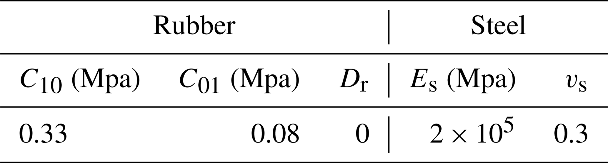
Due to the strong nonlinear properties of rubber materials, the hyperelastic constitutive model is generally used. This paper uses the Mooney-Rivlin constitutive model. In this simulation. The rubber mainly undergoes tensile deformation and Mooney-Rivlin model can be used to obtain relatively accurate simulation results. The hardness of the bellows rubber studied in this paper is 50 IRHD, and the estimated material coefficients are shown in Table 1 (Zhang et al., 2018). The rubber's incompressibility coefficient Dr is assumed to be 0. Since the rubber bellows are not limited in a large range, the influence of the incompressibility is negligible, and this assumption does not substantially affect the calculation result.
The steel is set as a linear elastic material and the coefficients are also shown in Table 1. Since the metal parts have little effect on the rubber deformation results, a rigid body constraint is applied to the upper and bottom end caps, the guide sleeve and the guide column to reduce the calculation cost. The rigid body reference point of the top end cap and the guide sleeve is RP-1; The rigid body reference point of the bottom end caps and the guide column is RP-2. The top and bottom end caps and the snap ring are tied to the outer side of the rubber bellows. The surface-to-surface contacts are established among guide column, guide sleeve, end caps, snap ring and rubber bellows.
An analysis step is established and the incremental step is fixed at 0.05. Then there are i=21 analysis sub-steps. A displacement boundary condition along +y direction is applied to RP-1, and the maximum displacement of the top end cap is 195 mm. A fixed constraint is applied to RP-2. The pressure compensator is assumed to work at 500 m under water, and a pressure of 5 MPa is applied to the outer surface of the rubber bellows. A pressure of 5.06 Mpa was applied to the inside to simulate internal pressure.
Figure 5 shows the deformation results of the pressure compensator. A sweep display is set in the post-processing to rotate the axisymmetric model into a three-dimensional model.
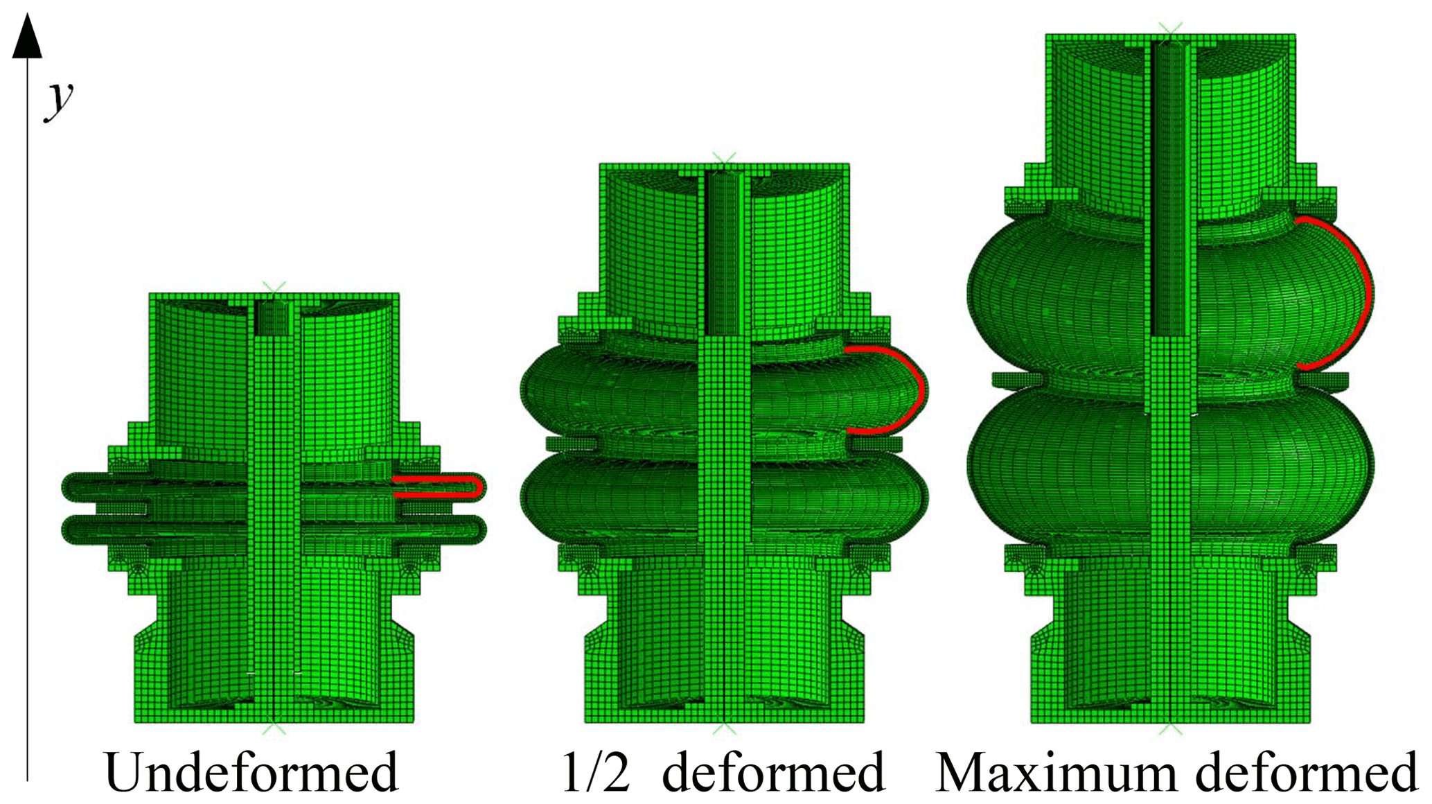
It can be seen that there are two oil chambers that have been deformed in the compensator due to the limitation of the snap ring. The volume of one oil chamber is expressed as Vr. In addition, the volume of the guide column occupying the oil chamber, Vd, also varies. The volume of the top and bottom end caps, the snap ring, and the guide sleeve, Vg, keeps constant and can be expressed as
where Vu is the volume of top end cap; Vb is the volume of bottom end cap; Vk is the volume of snap ring; Vt is the volume of guide sleeve. The closed oil chamber volume of the rubber bellows pressure compensator is
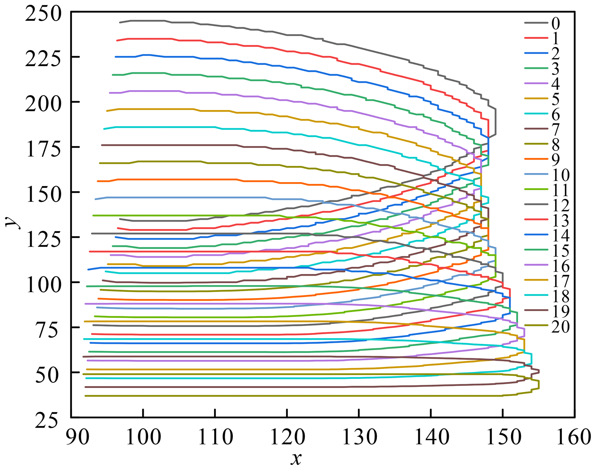
In order to calculate the volume of the oil chamber in the ith analysis sub-step, Vr(i), the coordinates of the nodes on the inner wall of the oil chamber (the red line shown in Fig. 5), (xn,yn), need to be obtained, as shown in Fig. 6. The volume of an oil chamber of the rubber bellows, Vr(x), is then calculated as
Discretize Eq. (9) as
where n is the node number. There are 137 nodes in total. The displacement of spring y(i) can be expressed as
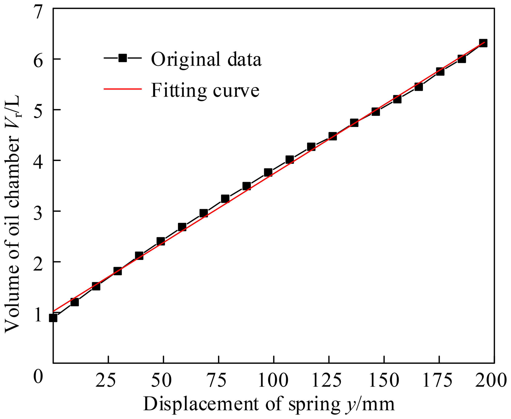
The results of Eqs. (10) and (11) are curve fitted using a polynomial method. Figure 7 shows the curve obtained by fitting. The curve is a linear fitting curve and the variance is 0.998. The curve equation is
For the studied compensator in this paper, Vg=1.2 L and Vd(x) can be expressed as
The dimensions of the above equations are unified to millimetre. Then the variation of the closed oil chamber volume of the pressure compensator can be expressed as
According to Eq. (14), the function of the closed oil chamber volume V(y) is linear with respect to the displacement y, and can be expressed as
Substitute the above equation into Eq. (5) and derives
For dynamic pressure compensation, the input flow qi comes from the motion of the hydraulic cylinder. It is assumed that the hydraulic cylinder moves at a constant speed within (0, 10 s), and the input flow rate is 18 L min−1. The hydraulic cylinder stops moving at 10 s, and the flow rate is zero. Then the input flow is a piecewise function
It is assumed that the initial capacity of the pressure compensator is 5 L. The spring initial is 32.3 mm calculated by Eq. (14).
It is assumed that the initial external pressure is 5 Mpa and the initial internal pressure is zero. Substitute initial conditions and main parameters of compensator into Eqs. (6) and (16)
In order to study the influence of different parameters on pressure fluctuation, the control variable method is used to calculate the variation of pressure when K, M, B and Ae take different values. Three groups of different parameters as shown in Table 2 are taken, and the group A is used as a control group. The hydraulic oil volume modulus E remains 1400 Mpa.
Table 2Parameter of a rubber bellows type pressure compensator.

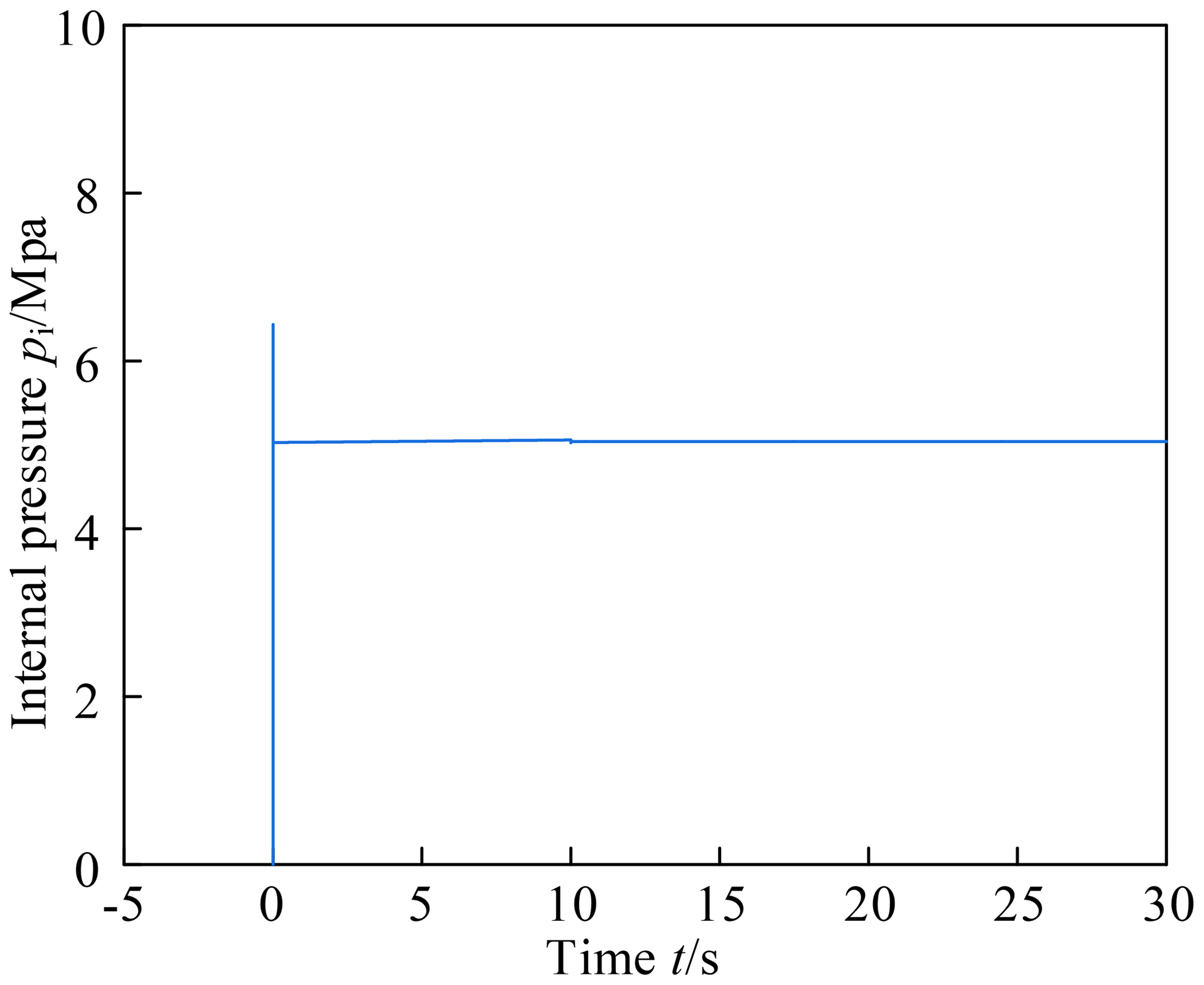
The numerical method is used to solve the differential equations, and the internal pressure variation of the compensator is calculated within 0–30 s. Figure 8 shows the internal pressure variation curve of the pressure compensator with parameters in Group A. It can be seen that the internal pressure has a certain overshoot before convergence, reaching about 6.4 Mpa. This overshoot may exceed the allowable pressure and break the pressure compensator. Therefore, the parameters should be carefully determined during the design process. The internal pressure then quickly converges to a value slightly higher than 5 Mpa. This value will increase slowly with 0–10 s. Since the amount of increase is very small, it is difficult to distinguish in the curve. At 10 s, the internal pressure makes a small fluctuation as the input flow momentarily becomes zero, and quickly converges to a final steady state result of 5.039 Mpa. This value is slightly higher than the external pressure of 5 Mpa, which prevents external seawater from entering the pressure compensator.
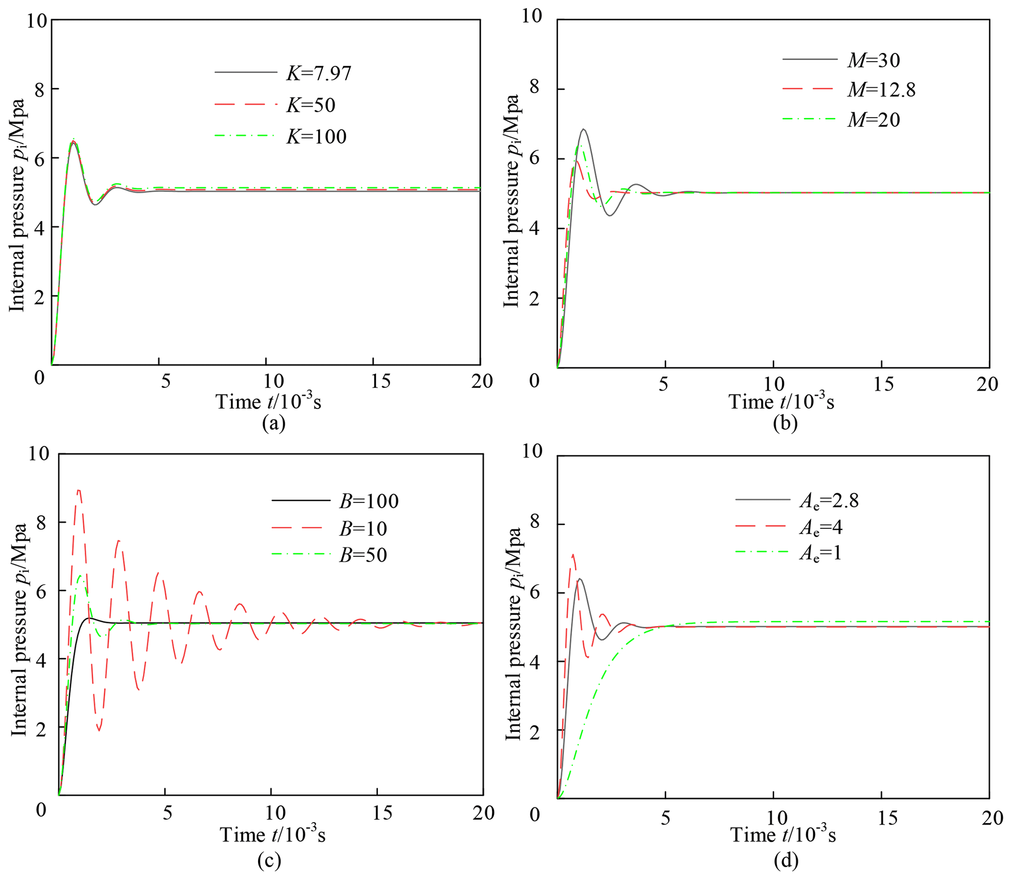
In order to analyze the pressure variations more clearly, the time is divided into 0–0.02, 0.02–10, 10–10.05 and 10.05–30 s to plot the internal pressure curve, as shown in Figs. 9–11. Figure 9 shows the internal pressure variation of the compensators with different parameters within 0–0.02 s. By comparing 4 figures, the overshoot can be reduced by reducing the spring stiffness, mass and effective area or increasing the damping. The spring stiffness has the least effect on overshoot. Since the damping ratio will be increased by reducing the mass or increasing the damping, the rate of convergence may also be increased. The variation in effective area does not affect the rate of convergence.
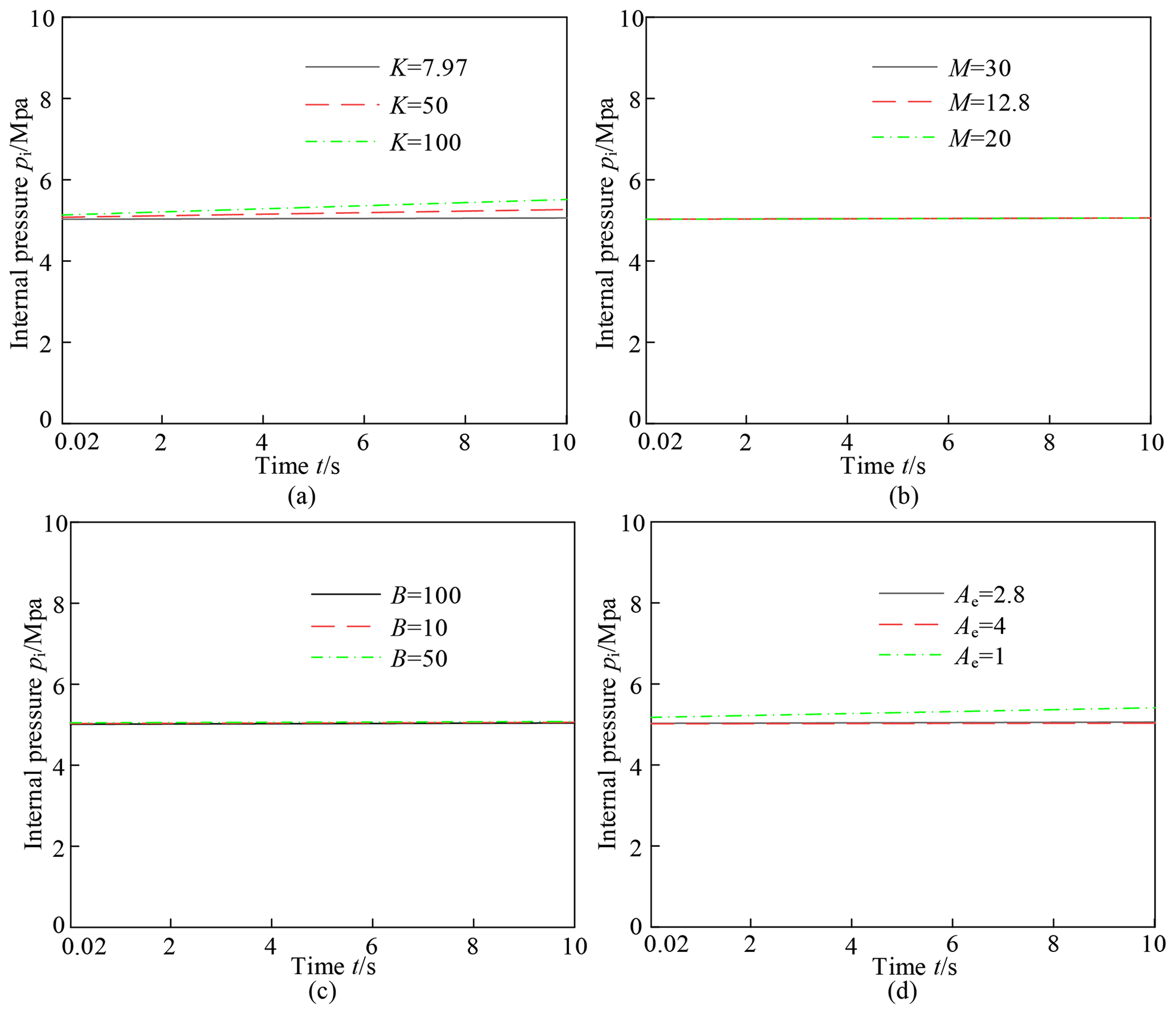
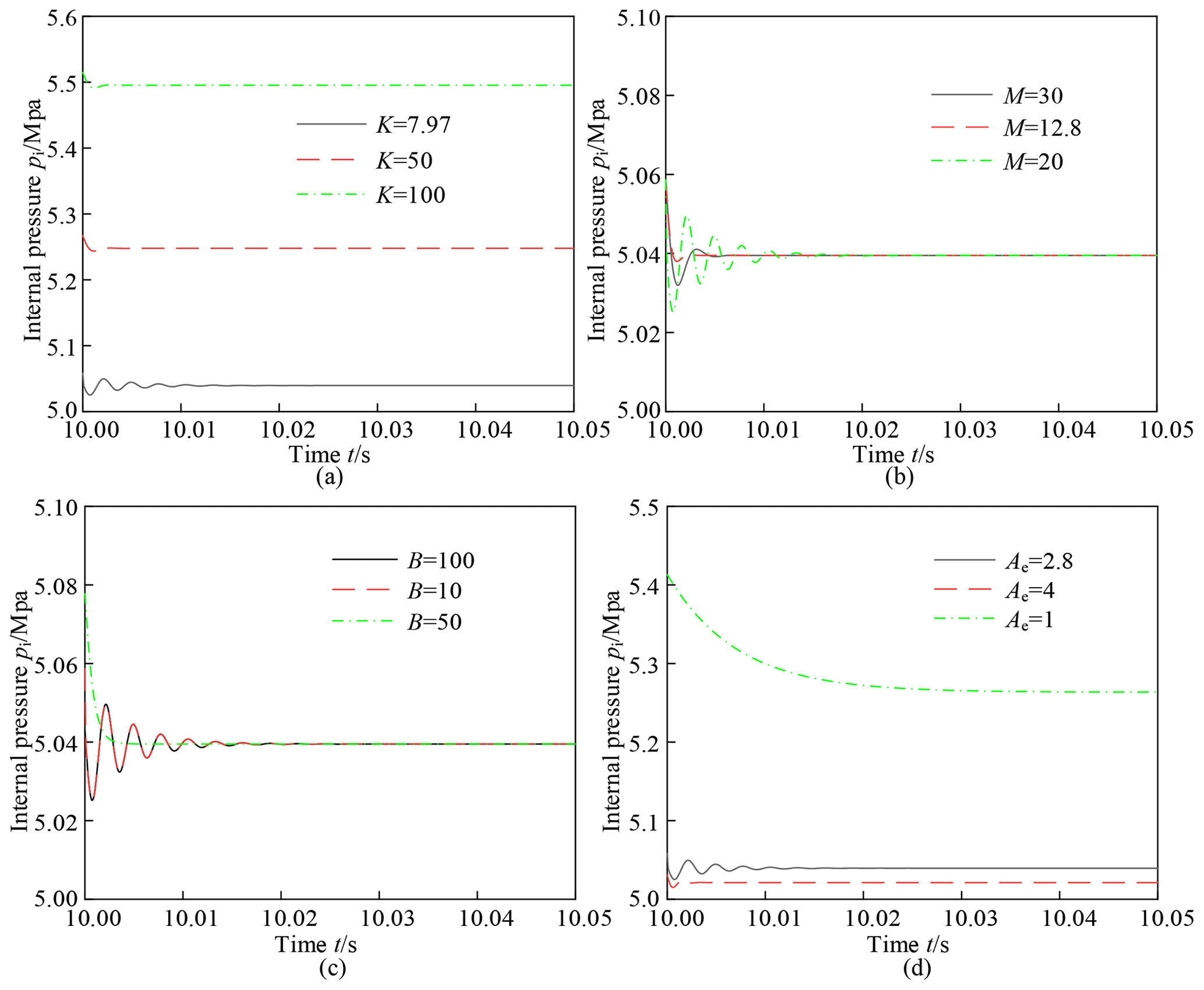
Figures 10 and 11 respectively show the internal pressure variations of the compensators with different parameters within 0.02–10 and 10–10.05 s. By comparing these figures, the spring stiffness and effective area have a significant influence on the final steady state result of internal pressure. An excessive spring stiffness or a too small area will extensively increase the internal pressure, which will also cause strength problems. Since the oil modulus E is much bigger than the mass M, the mass has little effect on the internal pressure. Since the hydraulic cylinder stops moving at 10 s, the internal pressure of the pressure compensator fluctuates and rapidly drops to the steady state value, as shown in Fig. 11.
This paper analyzes the dynamic pressure characteristics of the rubber bellows type compensator. The dynamic characteristic equation of the pressure is established. Due to the strong nonlinear characteristic of rubber, the finite element method is used to simulate the deformation process of the rubber-bellows type pressure compensator. The relationship between the volume variation and the spring displacement of the rubber-bellows type pressure compensator is calculated. The relationship is brought into the theoretical equation result to obtain the pressure characteristics of the compensator. Through the control variable method, the influence of damping B, total mass M, effective area Ae and spring stiffness K on the internal pressure of the compensator is obtained. According to the analysis result, the damping ratio should be appropriately increased to reduce the overshoot of pressure fluctuations in the design. Since the damping is difficult to control, the total mass of the end cap, the guide column, the rubber bellows and springs can be minimized. It also reduces the quality of the equipment. The spring stiffness and effective area have a significant influence on the steady-state pressure. A softer spring should be used and the effective area should be increased as much as possible to reduce the final steady-state pressure.
| pi | The pressure of the oil chamber |
| qi | The flow of the oil chamber |
| V(y) | The volume of the oil chamber |
| y | Spring displacement |
| Ae | The effective area of the rubber bellows |
| D | The outer diameter of the top end cap |
| po | External pressure |
| K | Tensile stiffness of the spring and rubber bellows |
| M | The total mass of end caps, guide columns, rubber bellows and springs |
| B | Viscoelastic coefficient |
| E | The bulk modulus of the hydraulic oil |
| C10, C01, Dr | Material coefficients of the rubber |
| Es,vs | Material coefficients of the steel |
| Vr | The volume of one oil chamber |
| Vd | The volume of the guide column |
| Vu | The volume of the top end cap |
| Vb | The volume of the bottom end cap |
| Vk | The volume of the snap ring |
| Vt | The volume of the guide sleeve |
| n | Node number |
All the data used in this paper can be obtained from the corresponding author on request.
The work is a product of the intellectual environment of the whole team; and that all members have contributed in various degrees to the research concept and to the execution of the numerical experiment. Project administration: SW and XD. Resources: KC. Analyzed model result: SL. SL wrote the paper. LZ reviewed and edited the paper.
The authors declare that they have no conflict of interest.
The authors wish to thank the support of the Science and Technology innovation and R & D project of CSIC (grant no. 2017J03).
This research has been supported by the Science and Technology innovation and R & D project of CSIC (grant no. 2017J03).
This paper was edited by Dario Richiedei and reviewed by two anonymous referees.
Bruno, F., Muzzupappa, M., Lagudi, A., Gallo, A., Spadafora, F., Ritacco, G., Angilica, A., Barbieri, L., Di Lecce, N., Saviozzi, G., Laschi, C., Guida, R., and Di Stefano, G.: A ROV for supporting the planned maintenance in underwater archaeological sites, in: MTS/IEEE OCEANS 2015 – Genova: Discovering Sustainable Ocean Energy for a New World, IEEE, Genoa, Italy, 2015.
Cao, X., Zhang, C., Deng, B., Xie, Q., and Rong, Y.: Research on Pressure-compensated Dynamic Property of Deep-sea Oil Reservoir Systems, Ocean Technol., 30, 83–87, 2011.
Greeneri, W. J.: Navy's deep ocean technology project evolution and progress, in: Oceans Conference Record (IEEE), IEEE, San Diego, USA, 1971.
Gu, L., Luo, G., Zhou, F., Wang, F., and Chen, Y.: Development and Future of Deep-sea Underwater Hydraulic Technique, Chinese Hydraul. Pneum., 12, 1–7, 2013.
He, J., Meng, Q. X., and Zhao, J.: The design of hydraulic pressure system for underwater interfacing manipulator, Hydraul. Pneum. Seals, 1, 22–24, 2007.
Hu, H., Long, L., Shen, X., and Zhang, W.: Research on pressure compensator used for deep-sea hydraulic system, Ocean Eng. Equip. Technol., 5, 209–213, 2018.
Li, Y.: Research on the pressure compensation for external hydraulic systems of submersible vehicles, ZheJiang University, Zhejiang, China, 2005.
Liu, H., Hu, Z., Ma, L., Tang, G., Hu, X., and Han, J.: Research on a rolling diaphragm pressure compensator used for deep-sea manned submersibles, Harbin Gongcheng Daxue Xuebao/Journal Harbin Eng. Univ., 37, 1313–1317, https://doi.org/10.11990/jheu.201504043, 2016.
Meng, Q., Wang, Z., Wei, H., and Zhang, L.: Development of Pressure Compensator for Deep Water Hydraulic Power Station, Sh. Eng., 2, 60–61, 2000.
Tian, Y., Persaud, R., Liu, S., Liu, T., Long, J., Xu, C., Sun, K., and Leng, J.: Research on Dynamic Characteristics of Deep Sea Pressure Compensator, IEEE, Marseille, France, 2019.
Torma, P. and Szepesvári, C.: Local importance sampling: A novel technique to enhance particle filtering, J. Multimed., 1, 32–43, https://doi.org/10.4304/jmm.1.1.32-43, 2006.
Wang, F.: Research on the key technology of underwater hydraulic system utilizing seawater pressure, ZheJiang University, Zhejiang, China, 2009.
Wang, F. and Chen, Y.: Design and experimental study of oil-based pressure-compensated underwater hydraulic system, Proc. Inst. Mech. Eng. Part I, 228, 221–232, https://doi.org/10.1177/0959651813514219, 2014a.
Wang, F. and Chen, Y.: Dynamic characteristics of pressure compensator in underwater hydraulic system, IEEE-ASME T. Mech., 19, 777–787, https://doi.org/10.1109/TMECH.2013.2260829, 2014b.
Wang, L., Li, S., Yao, S., Lv, D., and Jia, P.: Study on the vertical stiffness of the spherical elastic layer bonded between rigid surfaces, Arch. Appl. Mech., 87, 1243–1253, https://doi.org/10.1007/s00419-017-1246-9, 2017.
Wang, Q., Li, Y., Zhong, T., and Xu, G.: Pressure compensation method of underwater hydraulic system with hydraulic power unit being under atmospheric circumstance and pressure compensated valve, Chinese J. Mech. Eng. (English Ed.), 18, 419, https://doi.org/10.3901/cjme.2005.03.419, 2005.
Whitcomb, L. L.: Underwater robotics: out of the research laboratory and into the field, in: Proceedings – IEEE International Conference on Robotics and Automation, IEEE, San Diego, USA, 2000.
Yang, C., Wang, Y., and Yao, F.: Driving performance of underwater long-arm hydraulic manipulator system for small autonomous underwater vehicle and its positioning accuracy, Int. J. Adv. Robot. Syst., 14, https://doi.org/10.1177/1729881417747104, 2017.
Zhang, L., Li, Z., and Ma, X.: Study on Parameter Characteristics of Rubber Mooney-rivlin model, Noise Vib. Control, 38, 69–72, 2018.
Zhang, Y., Luo, G. S., Wang, F., and Lin-Yi, G. U.: Deep-sea pressure adaptive compensation technique for underwater robots, Mech. Electr. Eng. Mag., 24, 10–12, 2007.
- Abstract
- Introduction
- Theory analysis of the bellows type pressure compensator
- Calculation of pressure characteristics formulation
- Results and analysis of dynamic characteristics of pressure
- Conclusions
- Appendix A: Nomenclature
- Data availability
- Author contributions
- Competing interests
- Acknowledgements
- Financial support
- Review statement
- References