the Creative Commons Attribution 4.0 License.
the Creative Commons Attribution 4.0 License.
 | 27 May 2020
Study on power split characteristics of planetary multistage face gear transmission device and its effect to drive efficiency under variable speed working condition
Xingbin Chen
Peng Zhang
Xinhe Min
Nini Li
Zhanpeng Deng
The planetary gear system consists of several concentric single stage face gears symmetrically meshing with multiple cylindrical gears that as the core component of planetary multistage face gears transmission device (PMFGTD), which is the key to realizing shifting and principle innovation that able to flexibly extend the speed ratio region of single stage face gear. The speed ratio distribution mechanism is directly related to the feasibility of the design scheme. The stability, reliability and loading capacity of each power split branch affect the performance of the whole system directly. For the requirements of maximizing drive efficiency and optimizing drive performance under different conditions, this study analyzes the gear matching relationship and driving characteristics by using numerical calculation method basing on the PMFGTD structural characteristics, and calculates the corresponding transmission ratio value. According to the torque equilibrium equation, the torque relation and power ratio relation of each component are established, and then the power distribution relation between system components is calculated. The flow characteristics of system input power and each branch output power under the condition with or without meshing power loss are analyzed. The influence relationship model of power split coefficient on drive efficiency is established to calculate the corresponding rules, thus the dynamic characteristics of PMFGTD on power split under various working conditions are proved by experiments. The result provides reference for the transmission ratio distribution and structure design of planetary multistage face gears transmission.
- Article
(3222 KB) - Full-text XML
- BibTeX
- EndNote


Multistage face gear shifting mechanism is a planetary gear system consisting of meshing multiple face gears with cylindrical gears (Hu et al., 2019). Because the inevitable different errors of each individual gear in design, manufacturing, and installation, the uniformity of load distribution between the planetary gears directly affects the stability, reliability, bearing capacity and service life of transmission system. Therefore, it is great significant to study the load sharing characteristics of PMFGTD. To obtain the optimized loading capacity and drive efficiency, it is necessary to study the split characteristics of PMFGTD. For the split characteristics problems of planetary gears, some scholars have been studied on gear matching design, system configuration and parameter optimization. For example, Rama and Gnanasekar (2019) comparatively studied four different load cases by using a validated 3D single tooth spur gear FEM, such as case (1) Uniform load distribution along face width without considering load sharing between the pairs, case (2) Uniform load distribution along face width by including the effect of load sharing between the pairs, case (3) Actual load distribution along the face width without considering load sharing between the pairs, case (4) Actual load distribution along the face width by including the effect of load sharing between the pairs. The results of this study provide valuable guidelines for the crack propagation as well as life prediction calculations for spur gear drives (Rama and Gnanasekar, 2019). Kim et al. (2018) analyzed experimentally the effects of increasing the torque on and changing the rotation direction of a planetary gearbox on the dynamic load sharing among the planet gears by using a planet carrier manufactured at an industrial site. When the number of planet gears was even, one pair of planet gears exhibited higher load sharing than the other two pairs among the three pairs of planet gears. In addition, increasing the torque of the planetary gearbox improved the mesh load factor. The mesh load factor varied significantly as to the rotation direction changed, due to the phase change of the carrier pinhole position error (Kim et al., 2018). Nam et al. (2016) investigated the effects of non-torque loads on the load sharing and distribution of planet gears for wind turbine gearboxes through a scaled-down model experiment. The results obtained by applying only torque and by applying each non-torque load along with the torque were compared, and the mesh load factor and face load factor were used as indicators of the load sharing and distribution of planet gears, respectively. As a result, the load sharing became non-uniform when radial force and moments were added, resulting in increased mesh load factor about 3 %. The load distribution on the tooth face width did not show a clear difference for the non-torque loads because the face load factors did not show a clear difference among loading conditions (Nam et al., 2016). Lin et al. (2016) presented a gear matching scheme of four branches power structure under structural constraints and load sharing conditions. Based on cell-mapping method (CMM), two-dimensional dynamic domain planes have been developed and primarily focused on the parameters of backlash, transmission error, mesh frequency and damping ratio, and so forth. Solution demonstrates that Period-doubling bifurcation happens as the mesh frequency increases; moreover nonlinear discontinuous jump breaks the periodic orbit and also turns the periodic state into chaos suddenly (Lin et al., 2016). Yang et al. (2014) established a static model for two branches power split transmission system. For the purpose of calculating power-split value, a simplified algorithm is developed through formulating the deformation compatibility condition and the torque equilibrium condition. Under the elastic support, the static equilibrium equations should be built to calculate the power-split under different conditions based on the projection of installation error and elastic deformation on the line of action as described. The research results herein would be done to improve the applicability of tri-branching transmission (Yang et al., 2014). Yi et al. (2015) built a coupled dynamic model containing helical gears-shafts-bearings for a wind turbine gearbox transmission system to study the pinion floating structure. The analyzing results of the influence of average error and amplitude error on the load sharing show that the load sharing could be decreased if the error goes up a little. Then, by means of treating the static tracing point as the dynamic initial values, we analyzed the initial position's influence on the load sharing of transmission system to provide a theoretical basis of load sharing control (Yi et al., 2015). Hu et al. (2008) established a relationship model between the power split coefficient and the unit transmission ratio of the closed planetary gears, drew the power flow pattern and efficiency curve, selected the unit transmission ratio reasonably, avoided the power cycle within the system, and thus improved drive efficiency. On this basis of the torque, power balance equations and force analysis of the basic members, the power distributions of a 2K-H multistage micro-planetary gear reducer are analyzed under considering power losses or not, the overall transmission efficiency calculation of a 2K-H multistage micro-planetary gear reducer is more intuitive and easy to operate (Hu et al., 2008; Li and Hu, 2017; Li et al., 2017). In conclusion, the studies on the split characteristic of cylindrical gear have been carried out earlier, many achievements can be referenced. However, most models above studies were based on standardized single-stage planetary gears or fixed axis gears, but not on non-standardized planetary gears. At the same time, the split characteristic of multistage coupling structure only stayed on the static design performance of components, and without including the influence factors of inter-stage coupling. Even though, Lewicki et al. (2008) carried out an experimental fatigue tests study on the concept verification of the face gear split transmission system, it was proved that the floating support structure could improve the load sharing effect (Lewicki et al., 2008).
Comparing with traditional cylindrical gear split system, the structure with face gears could improve the power-to-weight ratio and reliability. Jin et al. (2019) proposed a new configuration of helicopter main gearbox with twice split paths based on the characteristics of the helicopter main reduction gearbox and combined with the advantages of face gear and cylindrical gear power dividing. Results show that with the increase of the backlash, the load-sharing coefficient decreases, the dynamic load coefficient increases, but the other drive stages are almost unaffected. Compared with split torque stages and power confluence stages, the load sharing and dynamic load coefficient of power input stages are the most sensitive to the backlash of the power input stage, and the appropriate increase of the backlash can effectively improve the dynamic properties (Jin et al., 2019). Mo et al. (2020) took the multi-power face gear split flow system as the research object. The impacts of manufacturing errors, assembly errors, manufacturing error phases, assembly error phases, meshing damping, support stiffness, and the input power on the load-sharing coefficients were analyzed. The research shows that the errors and error phases of spur gears have small impacts on the load-sharing coefficients, while the support stiffness of spur gears has a great impact on the load-sharing coefficients. The errors and error phases of face gears have small impacts on the load-sharing coefficients, while the support stiffness of spur gears has a great impact on the load-sharing coefficients. The load-sharing coefficients increase constantly with the increase in the meshing damping between face gears and spur gears, whereas the load-sharing coefficients decrease constantly (Mo et al., 2020). Dong et al. (2019) developed a new finite element model to determine the power directions of branches in concentric face gear split-torque transmission system (CFGSTTS). On the premise of meeting the assembly conditions, the effect of factors including load condition, distribution angle, layout form and the number of idlers on power directions in CFGSTTS is researched, and the impact of those factors on load sharing is also explored. The results reveal that the power directions in CFGSTTS are alterable, and the load sharing coefficients are affected obviously by structural parameters (Dong et al., 2019). Zhao et al. (2018) presented an original quasistatic load sharing analysis model to predict the load sharing behavious of concentric torque-split face gear transmission among paths. A number of numerical simulations of load sharing behaviour analysis are conducted. The mechanism of uneven load sharing is revealed. It is observed that the support stiffness of pinion and backlash have significant influences on the load sharing behaviours of the concentric torque-split face gear transmission (Zhao et al., 2018). Li et al. (2016) proposed a star pinion geometry phase adjustment solution, which is not to change drive ratios of differential face gear trains versus traditional geometry parameter adjustment solutions, and established a six DOF torsion dynamic model associated with four star pinions. Furthermore, discussed dynamic load sharing behaviors of two version differential face gear trains, and predicted the effects of star pinion geometry phase adjustments on two version differential face gear trains. The analytic results indicate the effects of the proposed star pinion geometry phase adjustments on dynamic load sharing behaviors of two version differential face gear trains are significant. These contributions would benefit to improve dynamic load sharing designs and engineering applications of differential face gear trains in the future (Li et al., 2016).
However, the planetary system introduction with multistage face gears is a novel research direction. The corresponding studies on split characteristics of multistage face gear were rarely found. The PMFGTD differential gear train has the remarkable characteristics of power split and confluence. The research on the power flow direction and transmission efficiency of each component of the coupling mechanism is helpful to ascertain the design accuracy and assembly error of the gears of each component, to obtain the relationship between the power flow distribution and the structural parameters in the system, and to reasonably select the unit transmission ratio. Thus, to optimize the matching scheme of system power split components, and improve transmission efficiency. This paper will study the drive mechanism and characteristics of PMFGTD from speed ratio selection and power split, analyze the relationship between power split characteristics and drive efficiency, obtain the power split rules, optimize transmission characteristics and design scheme of key components of planetary split.
PMFGTD includes not only differential bevel gears, but also combination with cylindrical gears and multistage face gears (Hu et al., 2019, 2018). The motion is transferred from the motor to the input shaft 1, driving the bevel gear 2 to mesh with the driven bevel gear 7, thus driving the cylindrical gear 3 coaxial with the tumbler 6 to rotate. Cylindrical gear 3 is meshed with face gears j, when need to change speed, a certain stage of face gears group is fixed, cylindrical gear 3 drives tumbler 6 to revolve under rotation force, so that it is made up a planetary gear assembly, the motion is transferred from the tumbler 6 to the output shaft 5, as shown in Fig. 1.
According to the transmission mechanism and assembly structure, the multistage face gears system has many advantages than normal multistage gear system or single-stage face gear system.
-
The multistage face gears are coaxial cylindrical shell that the space layout is flexible and the component structure is simple, which can effectively save space and reduce the weight of the transmission system.
-
Several multiple concentric but different teeth face gears are meshing with the cylindrical gears, that is why the gear pair can realize the multiple transmission ratio changes and flexibly extend the speed ratio area of the single-stage face gear. At the same time, there are some characteristics related to the stable transmission and high transmission efficiency.
-
The multistage face gears system can obviously improve the interchangeability of gear system while meshing with the standard involute cylindrical gears.
-
The symmetry of assembly structure is strong, the transmission speed change mechanism is simple, the control strategy is easy to match and the speed regulating actuator is easy to achieve.
Due to these advantages, the multistage face gears system can be widely used in the transmission field like the high speed overloaded or the micro fine. The system composed of cylindrical gear and multistage face gears is not only simplifying the structure and saving the space, but what the most important can be also setting the series of face gear according to transmission ratio locale.
Planetary gear is driven by moving shaft (Qiu et al., 2015), the ratio cannot be simply calculated by the equation of fixed shaft driving, but usually required the fixed planetary carrier method, moment method, graphic method and vector method, etc. For simplifying studying, the PMFGTD can be considered as a differential mechanism conforming to the 2K-H (NW).
According to the general equation of a fixed planetary carrier, the drive ratio of the transfer mechanism is obtained as:
In this equation, is the drive ratio between the tumbler H and input shaft 1 rotating with face gears j. is the drive ratio of the face gears j and input shaft 1 rotating with tumbler H. n1 is the input shaft 1 speed. nH is the tumbler H speed. nj is the face gears j speed. Zj is the face gear teeth number. Z7 is the driven bevel gear teeth number. Z3 is the cylindrical gear teeth number. Z2 is the driving bevel gear teeth number.
So:
The speed ratio relations of gear pairs can be defined as , , the kinematic relationship of each corresponding component can be expressed as:
When selecting the relevant tooth numbers to determine the drive ratio, the corresponding concentric, assembly, adjacency and other additional conditions should be also considered. For example, the teeth number of every stage face gear should be an integral multiple of planetary gears.
In this equation, qan is the adjacent center gear ratio between the installation angle and corresponding central angle a. is the turned angle. np is the planetary gears number. n cannot be a multiple of np. N is an integral multiple.
Based on above conditions, while the driving and driven bevel gears numbers are Z2=36 and Z7=19, the relationship between the planetary system transmission ratio and the cylindrical-face gears teeth numbers are shown in Table 1.
Table 1Relationship connecting tooth numbers of cylindrical, face gears and transmission ratios of planetary system.
The PMFGTD differential gear train has remarkable features of power splitting and converging (Qin et al., 2017). Studying on the power flow direction and drive efficiency of each component of the coupling mechanism is helpful to clarify the design accuracy and assembly error of each component gear, and obtain the relationship between the power flow distribution and structural parameters. Selecting a reasonable unit transmission ratio, to optimize the matching scheme of system power split component, and improve drive efficiency.
4.1 Power flow analysis of each component
It is necessary to clarify the determining rules for input and output power before analyzing each component power flow:
-
If the torque direction is consistent with motion, the component power would be defined as the input power.
-
If the torque direction is opposite to motion, the component power would be defined as the output power.
-
If the speed or torque is zero, the component would not transmit power.
Based on the PMFGTD structure principle, assuming the torque equilibrium equation without considering friction loss as:
In this equation, T1 is the driving bevel gear torque (sun gear). Tj is the face gear torque (gear ring). TH is the swing arm torque (planetary carrier).
So the power equilibrium equation is obtained:
The components torque relationships are solved from Eqs. (5) and (6):
The power ratios relationships are given by:
In this equation, P1 is the driving bevel gear power. Pj is the face gear power. PH is the swing arm power.
4.2 Power distribution relationship between system components
Based on the PMFGTD structure principle, if setting swing arm as an output component, it is needed to assume both the face gear combination and driving bevel gear as input components (Chen et al., 2019). The driving bevel gear rotation speed is constant, the face gear rotation speed is adjustable ( with unchanged direction, and the distribution coefficient is set as . Then the face gear rotation speed can be defined as at any time.
In this equation, is the variable speed range. is the ratio.
Substituting into the power equilibrium equation:
The distribution coefficient is changed with the rotation speed of face gear, which is the key to affect the power ratio. The speeds are different, and the two input components power ratios are also different. But the real decisive factors are the variable speed range ψ and the ratio R. R is smaller while ψ is larger, the face gear transmitted power is a larger percentage in total input power, and the smaller the opposite. If the face gear speed is constant but driving bevel gear shifting, the results are similar.
According to three basic components functions in planetary train, each component power flow characteristics of the system are analyzed. The input power is split by the driving bevel gears to the branches (P21, P22, P23 and P24) with four driven bevel gears, four cylindrical gears and planetary axles. Then, four planet gears drive the planet carriers (P31, P32, P33 and P34) to output power through the fixed face gears.
When ignoring the meshing power loss, the relationship between system input power and each branch is:
Also ignoring the meshing power loss, the relationship between the each branch powers and system output power is:
The driven bevel gears and cylindrical gears are fixed by a spline shaft on the planet carrier:
The four bevel gears meshing efficiencies are defined as α1, α2, α3 and α4, the meshing efficiencies of four cylindrical gears pairs and different stage face gears as β1j, β2j, β3j and β4j(j is corresponding to first, second and third stage). When the meshing power loss is including, the relationship between system input power and each branch power is:
When the meshing power loss is including, the relationship between each branch power and system output power is:
Actually, the multispeed transmission system real model includes not only bevel gears, multistage face gears components, but also components such as planet carriers, input and output drive shafts and bearings. It is inevitable to increase the power loss and reduce the transmission efficiency with the increase of components.
4.3 Calculation equation of drive efficiency
In the process of planetary transmission, the power loss includes meshing friction loss, hydraulic loss (oil agitation resistance or heat generation, etc.) and bearing friction loss (Yin et al., 2014). Therefore, the drive efficiency is one of the important indexes to reflect the reasonable distribution of power flow in planetary gear trains. A common equation of drive efficiency can be cited for the entire system or for each branch subsystem:
In this equation, η is the total drive efficiency. ηm is the meshing efficiency including meshing friction loss, in each split branch, ηm=αi or βij. ηB is the efficiency including bearing friction loss. ηH is the efficiency including hydraulic loss.
In practice, the planetary gear drive efficiency calculation is usually following the fixed axis basic meshing efficiency, the bearing friction loss efficiency can be almost neglected. And the hydraulic loss efficiency is also relatively slight in the medium or low speed. Therefore, the account efficiency without including hydraulic loss and bearing friction is not much different from the actual situation.
4.4 Influence of power flow distribution on drive efficiency
To simplify the study, Assuming that the design, machining and installation accuracy of each bevel gear, cylindrical gear, and face gear in each branch are the same, the contact conditions are equilibrium, and the force are balanced, so the meshing efficiency between the planetary shafts are equal. According to Eq. (10), the total system efficiency is:
According to the drive efficiency of the bevel gear, the corresponding parameters of three stage face gears are obtained respectively, the power flow distribution influence on the drive efficiency can be obtained by substituting the corresponding drive efficiency into Eq. (17), as shown in Fig. 2.
As the power flow distribution coefficient increases, the drive efficiency of planetary system decreases sharply and then slowly. This indicates that the more split branch dispersed in the entire transmission system, the more the meshing efficiency lost. However, to ensure the transmission stability, it is still necessary to set up a certain split branch on the planetary structure. As the face gear teeth number increases, the transmission ratio increases, it means that the output speed is reduced, but the load torque is not changed, so that the total transmitted power is reduced.
4.5 Discussion about the power flow distribution
The power flow distribution mechanism of PMFGTD was analyzed from structural characteristic above. Actually, there should also be some in-depth study as follow:
-
To simplify the study, only the tributary components with or without power loss are inductive defined. But the effects of acceleration and deceleration, friction damping, and time-varying mesh stiffness in transient meshing process caused by individual errors of each planetary component are not considered, which cannot completely reflect the actual load sharing status of the transmission system.
-
In subsequent studies, it is necessary to supplement the load sharing characteristics in dynamic meshing transmission process of the planetary system, not only considering the effects of the design, manufacturing, and installation errors of each gear component, but also the effects of the contact deformation, meshing wear, inter-stage coupling, and so on.
To verify the research results on the power split characteristics, the dynamic characteristics and drive performance of the PMFGTD should be determined under various conditions. This study intends to build an experimental platform to analyze the drive efficiency, which includes drive motor with variable frequency, prototype gear box with multistage face gears, torque and acceleration sensors, elastic coupling and magnetic powder loader, as shown in Fig. 3.
Figure 3Experimental platform of novel multistage face gears transmission mechanism (1: Variable frequency drive motor, 2, 4: ZJ series torque speed sensor, 3: Multistage face gears box model machine, 5: Magnetic powder loader, 6: Three-compartment stabilized voltage supply, 7: Control and test system).
5.1 Drive efficiency in deceleration process
Respectively setting the input speed 200, 300 and 500 r min−1, the magnetic powder brakes with no load or loaded by tension controller at 10, 20 and 50 Nm. The data is collected per minute, and the speed ratio is switched from low to high (2.8–3.2–3.6) per 10 min, 30 sets of data are collected continuously, as shown in Fig. 4.
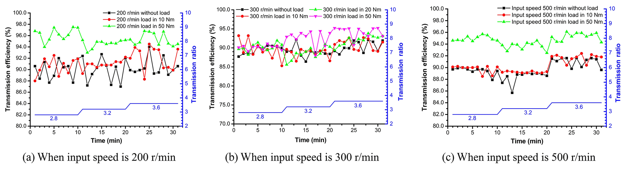
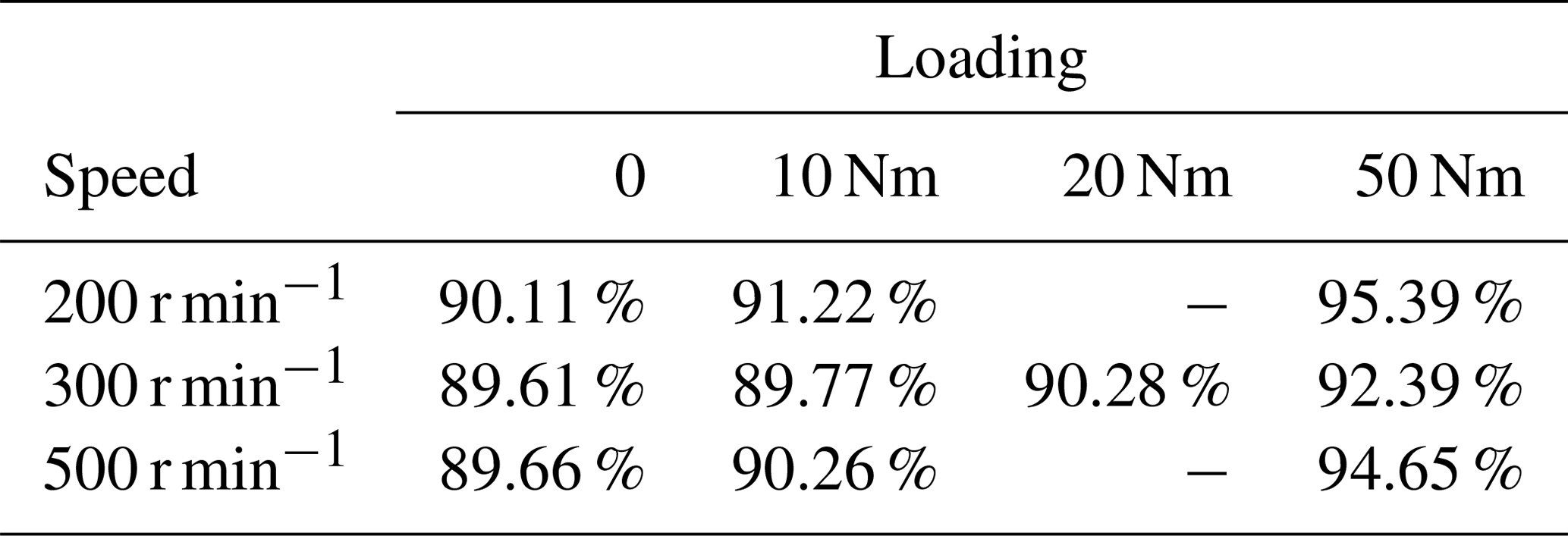
As the transmission ratio increases, the output speed decreases and the drive efficiency also becomes smaller. When no load or loads are 10, 20 and 50 Nm under different input speeds, the average drive efficiencies are shown in Table 2.
Table 2Average transmission efficiency in the deceleration process.
5.2 Drive efficiency in acceleration process
In the same way, the speed ratio is switched from high to low (3.6–3.2–2.8) per 10 min, and 30 sets of data are collected continuously, as shown in Fig. 5.
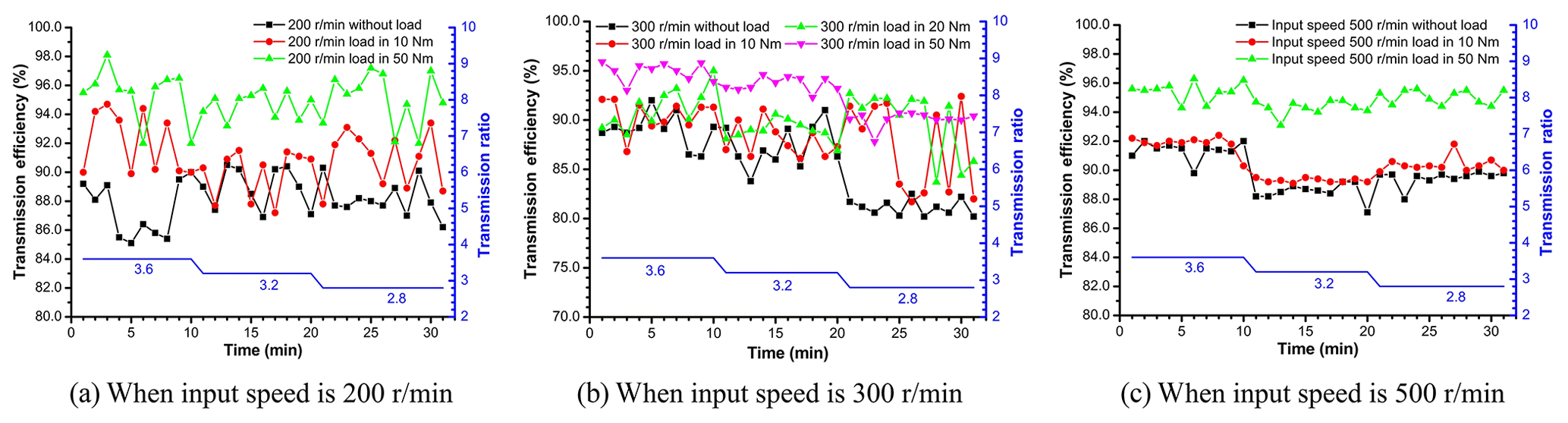
As the transmission ratio decreases, the output speed increases and the drive efficiency also becomes bigger. When no load or loads are 10, 20 and 50 Nm under different input speeds, the average drive efficiencies are shown in Table 3.
Table 3Average transmission efficiency in the acceleration process.

From comparative analysis of the experimental results, it is found that the power loss during the meshing process of the transmission system is much more complicated than the analytic analysis. Therefore, the transmission system is needed to further optimize from structural design, assembly accuracy and working condition adaptability.
Drive efficiency is a complex multi-factor system, especially for planetary multistage transmission system, which are not only affected by design error, machining error, installation error, but also by the planetary structure, split characteristics, meshing conditions, and corresponding excitation conditions. The numerical model established in this paper focuses on transmission ratio distribution conditions of each branch and drive efficiency with or without power loss, and other conditions are simplified. However, it is limited to the experimental conditions and the structural assembly characteristics of each component, the test can only be carry out for the whole multispeed transmission system, the experimental results of drive efficiencies are also corresponded to the whole transmission system.
Therefore, according to the structural principle of the planetary multistage transmission system, after counting include the split bevel gear pairs and cylindrical-face gears pairs, the average values of theoretical calculation results of drive efficiency are compared with the experimental measurements as shown in Table 4.
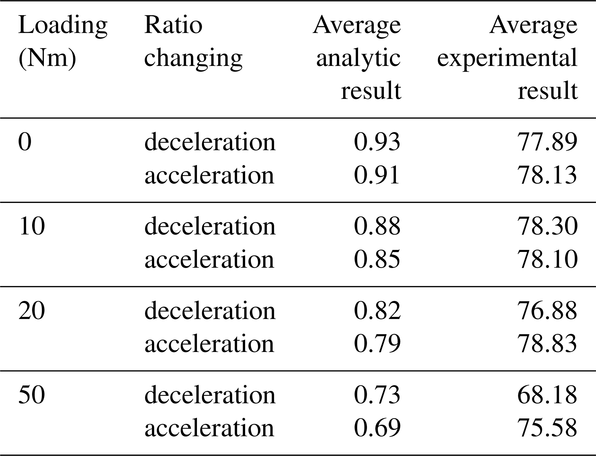
By comparison, the theoretical results are still quite different from the measurement results of the samples. Actually, the multispeed transmission system includes not only bevel gears, multistage face gears components, but also components such as planet carriers, input and output drive shafts and bearings. It is inevitable to increase the power loss and reduce the transmission efficiency with the increase of components. The research results have certain guiding significance for the design and processing optimization of structural systems.
In this paper, the transmission principle and mechanism of PMFGTD were studied, whose functional structure and corresponding speed ratio matching relationship were illustrated by decompositions of system components. The power distribution model was established according to the motion relation, and the influences of the branch distribution coefficient on stability, reliability and bearing capacity of system were analyzed. The transmission efficiency model was established by numerical method, and various factors influence on motion characteristics were analyzed in detail. The power split characteristics of PMFGTD influence on transmission efficiency were verified by experimental verification.
-
According to the system structure and transmission mechanism, the values of the transmission ratios have been determined, and the gear matching relationships of the planetary system have been analyzed.
-
According to the power equilibrium equation, the torque relationships and the power ratio relationships of each component have been established, and the power distribution relationships between the system components have been calculated. The flow characteristics of the system input power and each branch output power have been compared to analyze under the conditions with or without meshing power loss.
-
Establishing a relationship model of the influence of power flow distribution on drive efficiency, to calculate the corresponding rule, and study the rationality of the power split characteristics of PMFGTD has been verified under various working conditions through experimental verification.
The results analyzed the feasibility of PMFGTD to achieve variable speed-split, which were beneficial to improve the phenomenon, such as gear wear or damage, transmission discontinuity and motion unsmooth caused by uneven load distribution from planetary tributary, and also helpful to understand the influence of Transmission ratio distribution mechanism, planetary gear meshing state, power split characteristics on transmission efficiency. So that all these could provide reference for the speed ratio distribution and structure design finalization of PMFGTD, to a certain extent, obtain the optimization direction of dynamic design, and improve the planetary system drive stability and efficiency.
No data sets were used in this study.
ZP and MX conceived and designed the article; LN established the influence relationship model of power split coefficient on drive efficiency; DZ built experiment to determine the dynamic characteristics and drive performance; CX wrote the paper.
The authors declare that they have no conflict of interest.
The author(s) disclosed receipt of the following financial support for the research, authorship, and/or publication of this article: This work was supported by the National Key Research and Development Plan of China (grant no. 2017YFB1301401), and the Guangdong Provincial Enterprises Key Laboratory Foundation about Mid-High-end Industrial Robot Technology (grant no. 2018B030323027).
This research has been supported by the National Key Research and Development Plan of China (grant no. 2017YFB1301401) and the Guangdong Provincial Enterprises Key Laboratory Foundation about Mid-High-end Industrial Robot Technology (grant no. 2018B030323027).
This paper was edited by Guimin Chen and reviewed by two anonymous referees.
Chen, X. B., Hu, Q. C., Xu, Z. Y., and Zhu, C. N.: Numerical modeling and dynamic characteristics study of coupling vibration of multistage face gearsplanetary transmission, Mech. Sci., 10, 475–495, 2019.
Chen, X. B., Hu, Q. C., Xu, Z. Y., and Zhu, C. N.: Structure design and surface interference analysis of double crown surface configuration of multistage face gears, Vibroengineering Procedia, 18, 194–200, 2018.
Dong, J. X., Tang, J. Y., and Hu, Z. H.: Investigation of assembly, power direction and load sharing in concentric face gear split-torque transmission system, Meccanica, 54, 2485–2506, 2019.
Hu, Q. C., Duan, F. H., and Xie, C. X.: Dynamic Characteristics Analysis of Planetary Geared System with Plastic Gears, Cjcm: 5th China-Japan Conference on Mechatronics 2008, 223–227, 2008.
Hu, Q. C., Chen, X., Xu, Z., Mai, Q., and Zhu, C.: Study on kinematic characteristics of planetary multistage face gears transmission, Proc. Inst. Mech. Eng. D, 234, 1–14, https://doi.org/10.1177/0954407019855908, 2019.
Jin, G. H., Ren, W., Zhu, R. P., and Lu, F. X.: Influence of Backlash on Load Sharing and Dynamic Load Characteristics of Twice Split Torque Transmission System, J. Vib. Eng. Technol., 7, 565–577, 2019.
Kim, J. G., Park, Y. J., Lee, G. H., Lee, S. D., and Oh, J. Y.: Experimental Study on the Carrier Pinhole Position Error Affecting Dynamic Load Sharing of Planetary Gearboxes, Int. J. Precis Eng. Man., 19, 881–887, 2018.
Lewicki, D. G., Heath, G. F., Filler, R. R., Slaughter, S. C., and Fetty, J.: Face gear surface durability investigations, J. Am. Helicopter Soc., 53, 282–289, 2008.
Li, J. Y. and Hu, Q. C.: Dynamic Characteristics of Planetary Transmission with Thin-Walled Ring Gear on Elastic Supports under Different Working Conditions, Lect. Notes Electr. En., 408, 1023–1042, 2017.
Li, J. Y., Hu, Q. C., Zong, C. F., and Zhu, T. J.: Power Analysis and Efficiency Calculation of Multistage Micro-planetary Transmission, Power and Energy Systems Engineering, (Cpese 2017), 141, 654–659, 2017.
Li, Z. M. Q., Ye, W., Zhang, L. L., and Zhu, R. P.: Effect predictions of star pinion geometry phase adjustments on dynamic load sharing behaviors of differential face gear trains, J. Vibroeng., 18, 81–92, 2016.
Lin, H., Wang, S. M., Dowell, E. H., and Dong, J. C.: Bifurcation Observation of Combining Spiral Gear Transmission Based on Parameter Domain Structure Analysis, Math. Probl. Eng., 1–13, https://doi.org/10.1155/2016/3738508, 2016.
Mo, S., Yue, Z. X., Feng, Z. Y., Shi, L. J., Zou, Z. X., and Dang, H. Y.: Analytical investigation on load-sharing characteristics for multi-power face gear split flow system, P. I. Mech. Eng. C-J. Mec., 234, 676–692, 2020.
Nam, J. S., Park, Y. J., Han, J. W., Nam, Y. Y., and Lee, G. H.: The effects of non-torque loads on a three-point suspension gearbox for wind turbines, Int. J. Energ. Res., 40, 618–631, 2016.
Qin, Z. B., Luo, Y. G., Li, K. Q., and Peng, H.: A New Powertrain Design Approach for Power-Split Hybrid Tracked Vehicles, Proceedings of the Asme 10th Annual Dynamic Systems and Control Conference, https://doi.org/10.1115/DSCC2017-5069, 8 pp., 2017.
Qiu, X. H., Han, Q. K., and Chu, F. L.: Load-sharing characteristics of planetary gear transmission in horizontal axis wind turbines, Mech. Mach. Theory, 92, 391–406, 2015.
Rama, T. and Gnanasekar, N.: Investigation of the effect of load distribution along the face width and load sharing between the pairs in contact on the fracture parameters of the spur gear tooth with root crack, Eng. Fail. Anal., 97, 518–533, 2019.
Yang, X. F., Fang, Z. D., Zhang, Y. Z., and Han, Y. F.: Analysis of Power-Split for the Transmission System Based on Deformation Compatibility, Appl. Mech. Mat., 441, 291–294, https://doi.org/10.4028/www.scientific.net/amm.441.291, 2013.
Yi, P. X., Zhang, C., Guo, L. J., and Shi, T. L.: Dynamic modeling and analysis of load sharing characteristics of wind turbine gearbox, Adv. Mech. Eng., 7, 1–16, 2015.
Yin, H. B., Li, S. L., Zhang, H., Zhao, X. Y., and Zhang, J.: The power loss and efficiency analysis of a 3DOFs planetary gear box, Adv. Mater Res.-Switz., 835, 1285–1289, 2014.
Zhao, N., Li, W., Hu, T., Guo, H., Zhou, R. C., and Peng, Y. J.: Quasistatic Load Sharing Behaviours of Concentric Torque-Split Face Gear Transmission with Flexible Face Gear, Math. Probl. Eng., 2018, 6568519, https://doi.org/10.1155/2018/6568519, 2018.
- Abstract
- Introduction
- Transmission mechanism analysis
- Transmission ratio and kinematic relationship analysis
- Power flow and drive efficiency analysis
- Drive performance experiment for multistage face gears transmission device
- Conclusions
- Data availability
- Author contributions
- Competing interests
- Acknowledgements
- Financial support
- Review statement
- References