the Creative Commons Attribution 4.0 License.
the Creative Commons Attribution 4.0 License.
 | 14 May 2020
Design and implementation of speed fluctuation reduction for a ball screw feed system at low-speed operation
Zhaoguo Wang
Fuxin Du
Hui Li
Zhe Su
In the high-precision servo feed system, when the permanent magnet synchronous motor (PMSM) is operated at low speed in the classical drive feed system (CDFS), the speed fluctuation caused by the motor torque harmonics seriously affects the speed smoothness of the servo system. In this paper, a novel double-drive differential feed system (DDFS) is proposed to effectively suppress the effect of torque harmonics of PMSM on speed fluctuation of the linear feed system at low-speed operation. Firstly, the effect of motor torque harmonics on motor speed for the DDFS is analyzed by the sensitivity function of the servo system, which indicates that the torque harmonics have little effect on the motor speed at high-speed operation. Then, in the DDFS, we make two motors rotate in the same direction at high speed and differentially synthesize at the ball screw to obtain low-velocity linear motion. Compared with the CDFS, the DDFS can suppress the effect of motor torque harmonics on speed fluctuation of the table and improve speed smoothness at low-speed operation.
- Article
(2237 KB) - Full-text XML
- BibTeX
- EndNote


In the high-precision manufacturing industry, higher requirements are placed on the dynamic response speed and speed smoothness of the servo feed system at low speed. Permanent magnet synchronous motors (PMSMs) are widely used in high-precision servo feed systems since they have high reliability, efficiency, and a torque inertia ratio with a fast dynamic response (Pillay, 1990; Jahns and Soong, 1996). However, when the motor is rotating at low speed, the speed fluctuation caused by motor torque harmonics will seriously affect the performance of the servo system (Houari et al., 2018; Qian et al., 2004). According to the difference of frequency values, the torque harmonics of the PMSM can be divided into the low-frequency components and the high-frequency components. The high-frequency components can be effectively suppressed by controlling loop bandwidths, and the low-frequency components within the controlling loop bandwidths need special handling (Houari et al., 2018; Chan et al., 1994). Therefore, in order to increase the speed smoothness of the servo system, when the motor operates at low speed, it is necessary to suppress the low-frequency components that cause the motor torque fluctuation.
The speed fluctuation of a PMSM is affected by many factors at low speed, e.g., cogging torque, current measurement errors, and flux harmonics (Guemes et al., 2011; Gebregergis et al., 2015). To effectively reduce the speed fluctuation, many valuable methods have been proposed and verified to suppress motor torque ripple. Generally, these methods are usually divided into two groups. The first group focuses on motor design improvement, such as skewing the slot or magnet (Binns et al., 1993; Carlson et al., 1989), using a fractional number of slots per pole (Chung et al., 2012; Senol and Ustun, 2011; Donato et al., 2010; Cavagnino et al., 2013), or optimizing the winding distribution (Nakao et al., 2014; Gebregergis et al., 2015). The torque ripple can be effectively reduced by optimizing the motor design. However, the optimization of motor design is limited by the development of new technologies, and they can result in higher manufacturing cost and a further complicated realization. The second group uses advanced control methods, which regulate the input current or voltage to reduce torque ripple (Panda et al., 2008). Houari et al. (2018, 2015) proposed an effective method to reduce speed fluctuation of PMSM at low speed, which improved the conventional PMSM controller by superposing an appropriate compensation signal on the quadratic-current reference. Xia et al. (2015) proposed a speed and current proportional–integral–resonant (PIR) control strategy to reduce speed fluctuation for the low-speed high-torque PMSM drive system. Qian et al. (2005) proposed two iterative learning control (ILC) schemes implemented in the time domain and frequency domain, respectively, to suppress speed ripples due to torque ripple at low speed. Using a robust iterative learning control algorithm (ILC) based on an adaptive sliding mode control (SMC) technique, the motor torque ripple was effectively suppressed, and the anti-interference ability of the servo system was improved (Liu et al., 2018). Tan et al. (2011) proposed the identification and compensation method of torque ripple based on steady-state error analysis, in which the function of torque ripple was determined by the least-squares method and the compensation of torque ripple was achieved by a programmable multi-axis controller (PMAC). The advantage of the above method is that the controller is a component of the servo system and does not require additional hardware. However, this method requires a special control algorithm to be written, which is complicated to implement.
In this paper, a novel DDFS is proposed to reduce the influence of torque harmonics of PMSM on velocity fluctuations of a table for a linear feed system at low-velocity operation. In the DDFS, the screw and nut are both driven by PMSMs, which rotate in the same direction at high speed and differentially synthesize at the ball screw pair to obtain low-velocity linear motion. This design ensures the driven table travels at low velocity while guaranteeing the two motors rotate at high speed, in which the high-frequency components of the torque ripples limited by the bandwidth of the servo system suppress the influence of the motor torque ripple on the velocity fluctuation of the table. Compared with the CDFS, the DDFS can reduce the effect of motor torque harmonics on the speed fluctuation of the table and improve speed smoothness at low-speed operation.
The remainder of this paper is arranged as follows. The DDFS structure and its control strategy are described in Sect. 2. The speed fluctuation caused by motor torque harmonics is analyzed in Sect. 3. The influence of motor torque harmonics on motor speed for the DDFS is analyzed by the sensitivity function of the servo system in Sect. 4. The velocity fluctuations of the table for the DDFS compared with the CDFS are simulated in Sect. 5. The experimental results validate the effectiveness of the proposed method in Sect. 6. The paper is concluded in Sect. 7.
2.1 The DDFS structure
In the CDFS, the screw shaft is driven by a servo motor through a coupling and the rotary motion of a motor is converted into linear motion of the table. Compared with the CDFS, the DDFS structure based on the nut-driven ball screw pair is illustrated in Fig. 1.

In the DDFS, the screw shaft and screw nut are both driven by PMSMs, which rotate in the same direction at high speed and differentially synthesize though the ball screw pair to obtain low velocity of the table. This design ensures the driven table travels at low velocity while guaranteeing the two motors rotate at high speed. Superposing two rotating speeds of PMSMs at high speed by the ball screw pair, the driven table could obtain low velocity and effectively avoid the crawling zone of the motors at low speed (Du et al., 2018a, b, 2017; Yu and Feng, 2015). In the DDFS, when the nut servo motor does not rotate, the DDFS changes to the CDFS.
2.2 PMSM model
Assuming that the PMSM iron loss, eddy current loss, and hysteresis loss are not considered, the d–q axis current equation in the stator d–q axis rotation reference coordinate system can be described as follows:
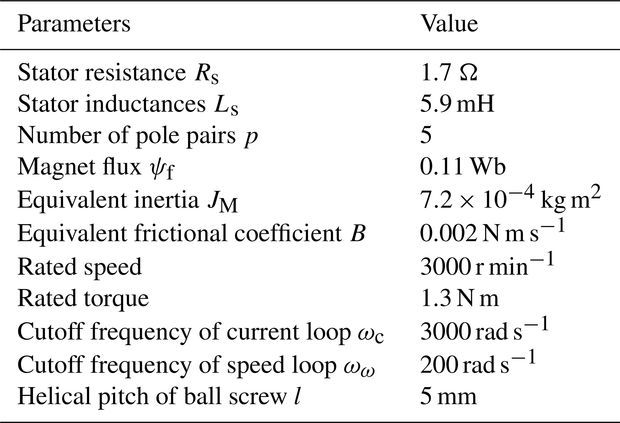
where p is the number of pole pairs, ωe is the electrical angular speed, Rs is the stator resistance, ud and uq are the voltages of the stator along the d and q axes, respectively, Ld and Lq are the inductances of the stator along the d and the q axes, respectively, id and iq are the currents of the stator along the d and q axes, respectively, TL is the load torque, Te is the electromagnetic torque, B is the viscous friction coefficient equivalent to the motor shaft, and JM is the moment of inertia equivalent to the motor shaft, including the motor shaft moment of inertia, the screw moment of inertia, the coupling moment of inertia, and the mass of the table.
When the id=0 vector control is performed on the PMSM, the electromagnetic torque of the motor is largest, and the electromagnetic torque can be shown as follows:
For the surface-mounted PMSM used in this paper, Ld and Lq are equal and the electromagnetic torque is simplified as follows:
The parameters of the servo system for the DDFS are shown in Table 1.
2.3 Control strategy of the DDFS
The speed fluctuation of the DDFS is mainly studied in this paper; therefore, the PMSMs are set to work under the speed loop. The conventional PI control strategy is adopted for the PMSMs with the same parameters selected. The control strategy of the DDFS is shown in Fig. 2.
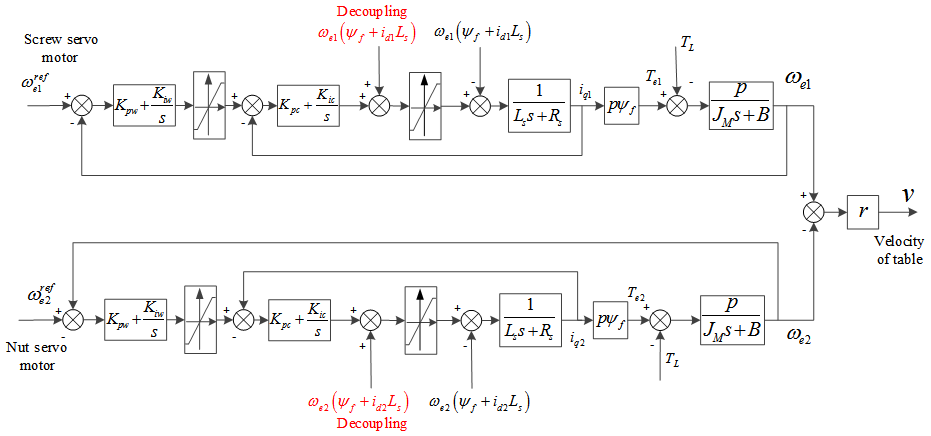
When the velocity of the table is required, the velocity signals of the screw motor and of the nut servo motor are given by the servo drivers of the two motors, respectively. The velocity of the table can be obtained by the ball screw pair.
where v is the velocity of the table, ω refe1 and ω refe2 are the electrical angular speed reference value of the screw servo motor and the electrical angular speed reference value of the nut servo motor, respectively, r is the transmission coefficient, l is the helical pitch of the ball screw, and p is the number of poles of the PMSM.
The current loop controller and speed loop controller are designed by a simple pole placement strategy. When the current loop bandwidth is selected, the current loop adjustment response time is required to be as small as possible and the current loop is required to have good disturbance performance. When selecting the speed loop bandwidth, it is necessary to ensure a better control target while avoiding mutual interference between the current loop and the speed loop.
The control parameters of the current loop and speed loop are as follows:
where Kpc is the current loop proportional gain, Kic is the current loop integral gain, ξ is the damping coefficient, ξ=0.7, ωc is the current loop cutoff frequency, Kpω is the speed loop proportional gain, Kiω is the speed loop integral gain, and ωω is the speed loop cutoff frequency.
When the PMSM is controlled at low speed, the main influence factors for the speed fluctuation of a motor are current sensor offset error, gain mismatch, and flux harmonics.
3.1 Current sensor offset error
Due to the dc offsets present during phase current detection and controller input conversion, the phase current measured by the sensor is deviated. The torque ripple due to the stator current measurement error can be expressed as follows (Houari et al., 2018):
where Δia and Δib are the offset errors, β is a constant, θe is the electrical angle, and α is a constant displacement of the angle.
3.2 Gain mismatch
The frequency of the torque ripple caused by the current sampling error is twice the fundamental frequency, and the torque fluctuation caused by the current sampling error can be expressed as follows (Houari et al., 2018):
where γ is the sensor gain deviation.
3.3 Flux harmonics
The non-sinusoidal flux linkage in the air gap is another factor that causes torque ripple. The torque harmonics of the 6th and multiples of the 6th caused by the non-sinusoidal flux linkage can be expressed as (Houari et al., 2018)
where T6i is the amplitude of the multiple of six harmonics.
3.4 Speed fluctuation analysis
The motor electromagnetic torque Te can be expressed as the sum of the main dc component (T0) and the harmonic components (ΔT).
The motor electromagnetic torque Te contains the 1st, 2nd, 6th, and 12th harmonics. The presence of these harmonics can cause speed fluctuations, especially when the motor rotates at low speed.
The relationship between the motor output speed ωe,i, the motor input speed ω refe,i (), and the disturbance TL can be obtained by the Laplace transform as shown in the following equation.
where H(s) and S(s) are the closed loop transfer function and the sensitivity function, respectively. The expressions of H(s) and S(s) are listed in Appendix A.
The Bode magnitude plot of S(s) is shown in Fig. 3, in which the horizontal axis represents the electrical angular speed of the PMSM. The torque harmonics are regarded as the disturbance signals. Figure 3 shows that as the electrical angular speed increases, the influence of the torque harmonics on the torque ripple increases first and then decreases. When the DDFS is used, according to the Bode magnitude plot of the S(s), the high-speed operating conditions with less influence of torque harmonics on motor speed fluctuations are selected for the both PMSMs to achieve low velocity of the table through ball screw pair differential synthesis, which can effectively improve velocity smoothness of the table at low velocity compared with the CDFS.
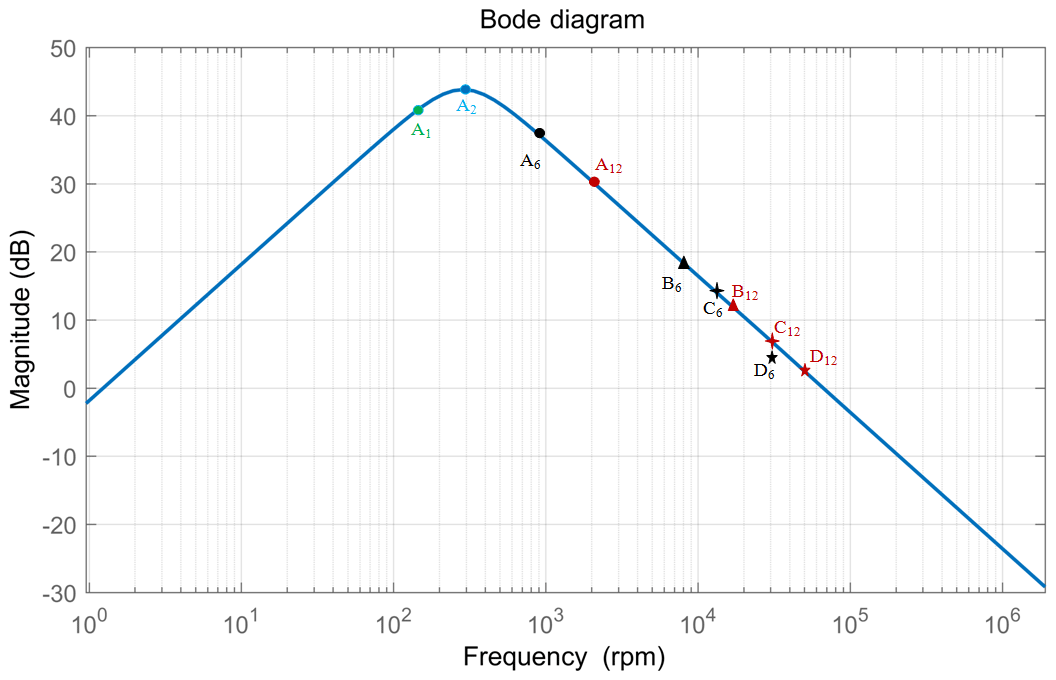
The analysis was carried out with an example of the table velocity 2.5 mm s−1. When the CDFS is used, the corresponding motor speed is 30 r min−1 (the electrical angular speed corresponding to the 6th harmonic of the motor is 900 rpm and is marked A6; the electrical angular speed corresponding to the 12th harmonic of the motor is 1800 rpm and is marked A12). In the DDFS, when the nut servo motor speed is 300, 500, and 800 rpm, the electrical angular speed of the 6th harmonic of the nut servo motor is marked B6, C6, and D6, and the electrical angular speed of the 12th harmonic of the nut servo motor is marked B12, C12, and D12, respectively.
The electrical angular frequency corresponding to the above torque harmonics is marked in Fig. 3. Because the screw servo motor speed is only 30 rpm higher than the nut servo motor in the DDFS, the screw servo motor torque harmonics are located near the corresponding torque harmonics of the nut servo motor. It can be seen from Fig. 3 that the Bode magnitude plot of S(s) has better suppression of the harmonic torque of the PMSM for the DDFS at a high speed, and the low velocity of the table is obtained by both motors' synthesis. It can effectively reduce the velocity fluctuation of the table compared with the CDFS.
To simulate the velocity fluctuation of the table at low velocity for the DDFS compared with the CDFS, the torque harmonics caused by a non-sinusoidal flux density distribution is simulated by using Eq. (15), in which the 6th and 12th torque components are taken as 6 % and 2 % of the rated torque, respectively (Houari et al., 2015). The velocity ripple factor (VRF) is used to evaluate the velocity fluctuation of the table, which indicates the percentage of the velocity deviating from the reference velocity.
where Vpk-pk is the peak-to-peak value of the velocity fluctuation for the table and is the reference velocity of the table.
The reference velocity 2.5 mm s−1 of the table is selected for analysis under the load of 1 Nm. Figure 4 shows the velocity fluctuation of the table for the DDFS at different synthesis speeds of both PMSMs compared with the CDFS (the speed of the nut servo motor is 0 mm s−1) when the reference velocity of the table is 2.5 mm s−1. Figure 4a shows the comparison of the table velocity fluctuations of CDFS and DDFS when the nut servo motor speed is 300 rpm in the DDFS. Figure 4b shows the comparison of the table velocity fluctuations of CDFS and DDFS when the nut servo motor speed is 500 rpm in the DDFS. Figure 4c shows the comparison of the table velocity fluctuations of CDFS and DDFS when the nut servo motor speed is 800 rpm in the DDFS.
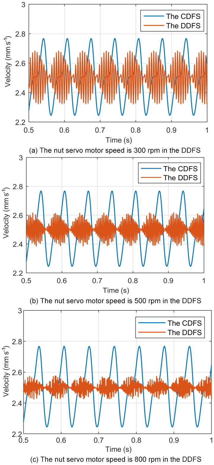
Figure 4Comparison of the table velocity fluctuations of CDFS and DDFS at 2.5 mm s−1 under 1 N m load torque.
Figure 4 indicates that the two motors can be synthesized at a high speed to obtain a low velocity of the table in the DDFS, which can effectively reduce the velocity fluctuation of the table compared with the CDFS.
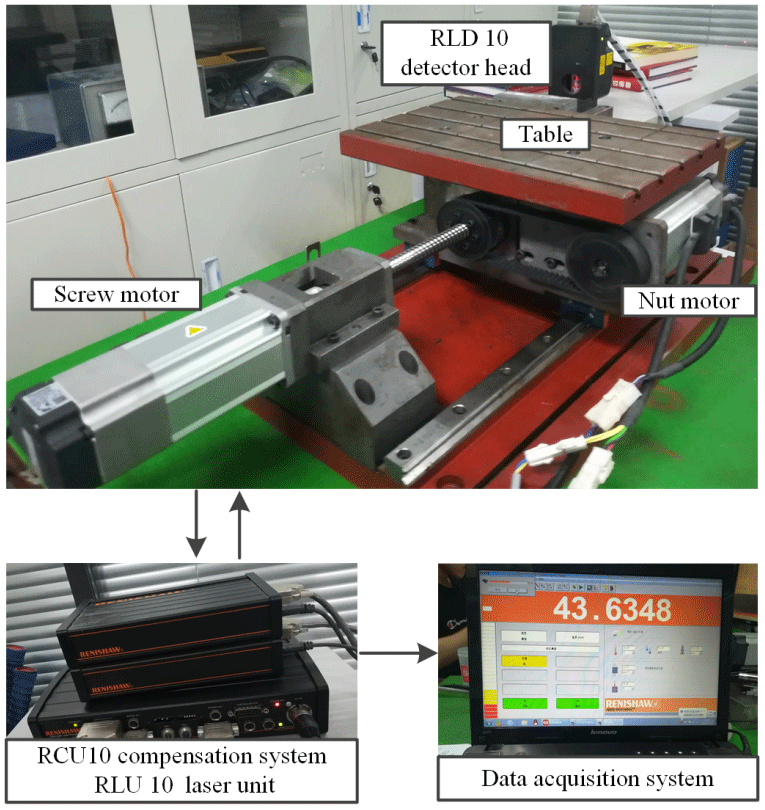
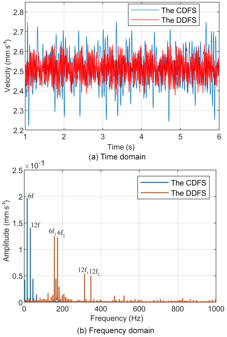
Figure 6Comparison of the table velocity fluctuations of CDFS and DDFS when the nut servo motor speed is 300 rpm in the DDFS.
In order to compare the velocity fluctuations at low velocity of the table for the CDFS and the DDFS, the experimental setup device is shown in Fig. 5. The experimental equipment includes the DDFS, Renishaw RLE 10 fiber laser scale (RLD 10 detector head, RLU 10 laser unit, RCU 10 compensation system), and data acquisition system. In the experiments, the sampling frequency of the fiber laser scale is set to 10 kHz.
When the CDFS is used, the speed of the nut servo motor is set to 0 rpm and the table is driven only by the screw servo motor. When the DDFS is used, we make both motors rotate in the same direction at high speed and differentially synthesize by the ball screw pair to obtain low velocity of the table.
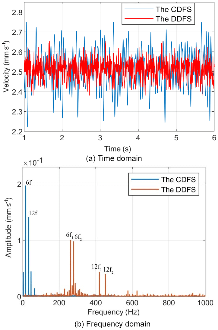
Figure 7Comparison of the table velocity fluctuations of CDFS and DDFS when the nut servo motor speed is 500 rpm in the DDFS.
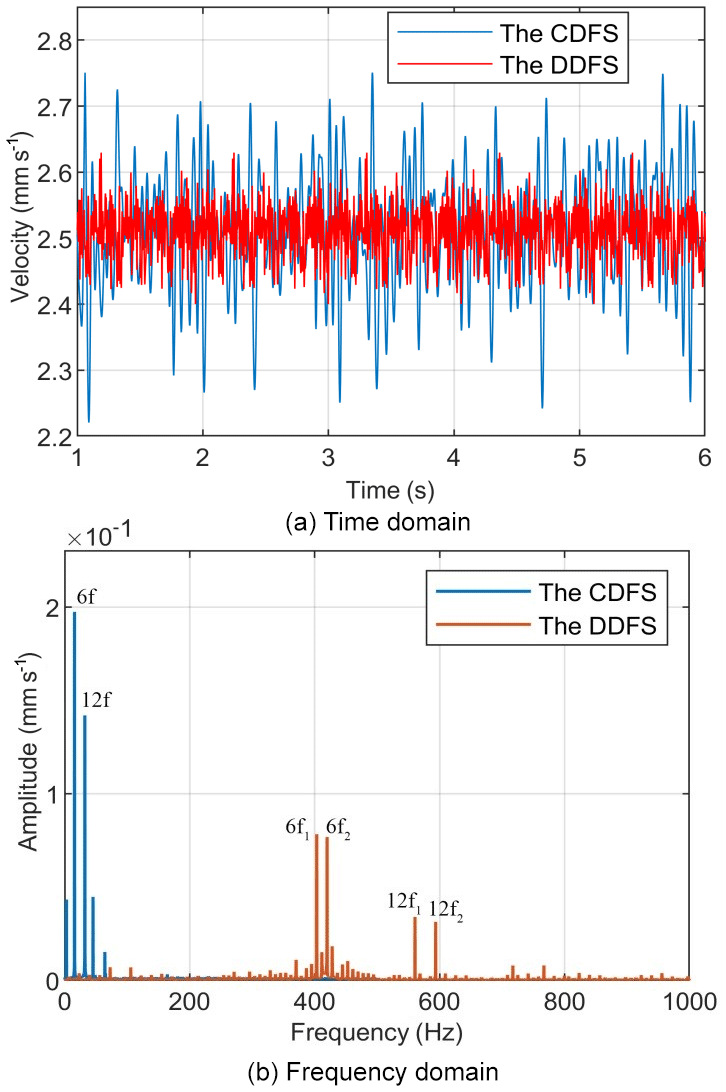
Figure 8Comparison of the table velocity fluctuations of CDFS and DDFS when the nut servo motor speed is 800 rpm in the DDFS.
The velocity fluctuations of the table for the DDFS at different synthesis speeds of both PMSMs compared with the CDFS are studied when the reference velocity of the table is 2.5 mm s−1. Figures 6, 7, and 8 show a comparison of the time and harmonic spectrum for the table velocity fluctuations of CDFS and DDFS when the nut servo motor speeds are 300, 500, and 800 rpm in the DDFS, respectively. From Fig. 6 it can be seen that the VRF rates of the table are decreased from 20.1 % with the CDFS to 13.4 % with the DDFS, when the speed of the nut servo motor is 300 rpm in the DDFS. Figure 7 indicates that the VRF rates of the table are decreased from 20.1 % with the CDFS to 10.6 % with the DDFS, when the speed of the nut servo motor is 500 rpm in the DDFS. Figure 8 illustrates that the VRF rates of the table are decreased from 20.1 % with the CDFS to 8.2 % with the DDFS, when the speed of the nut servo motor is 800 rpm in the DDFS.
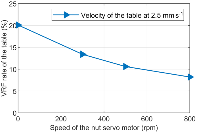
When the velocity of the table is 2.5 mm s−1 in the DDFS, the VRF rate of the table varies with the speed of the nut servo motor as shown in Fig. 9, which indicates that the VRF rate of the table gradually decreases with the increase in the speed of the nut servo motor in the DDFS. Compared with the CDFS, the DDFS can significantly improve the low-velocity smoothness of the table.
In this paper, a novel DDFS is developed to reduce the influence of torque harmonics of PMSM on speed fluctuations of a linear feed system at low-speed operation.
Some conclusions can be drawn as follows.
-
The law of the influence of motor torque harmonics on motor speed for the DDFS is analyzed by the sensitivity function of the servo system, which indicates that the torque harmonics have little effect on the motor speed at high-speed operation.
-
According to the law of the influence of motor harmonics on motor speed in the DDFS, we make two motors rotate in the same direction at high speed and differentially synthesize at the ball screw to obtain low-velocity smoothness linear motion.
-
The analysis is carried out with an example of the table velocity 2.5 mm s−1, which indicates that the VRF rate of the table gradually decreases with the increase in the speed of the nut servo motor in the DDFS. Compared with the CDFS, the DDFS can significantly improve the low-velocity smoothness of the table.
The closed loop transfer function H(s) and the sensitivity function S(s) can be expressed as follows:
All data included in this study are available upon request by contact with the corresponding author.
ZW made substantial contributions to the conception and design, the acquisition, the analysis, and the interpretation of data for the work. He also drafted the work or revised it critically for important intellectual content. ZW made a contribution to the acquisition of simulation experimental data and data collation. XF supervised and structured the process of the paper. FD helped in making figures. HL checked the writing language. ZS helped in the writing language.
The authors declare that they have no conflict of interest.
The authors wish to thank the support of the Science and Technology Development Plan of Shandong Province (grant no. 2015GGX103036).
This work is fully supported by the Science and Technology Development Plan of Shandong Province (grant no. 2015GGX103036), the National Natural Science Foundation of China (grant no. 51375266), the Young Science Foundation Project of China (grant no. 51705289), the Key Research & Development Program of Shandong Province (grant no. 2019GGX104101), and the Natural Science Foundation of Shandong Province, China (grant no. ZR2017PEE005).
This paper was edited by Zi Bin and reviewed by Assylbek Jomartov and one anonymous referee.
Binns, K. J., Chaaban, F. B., and Hameed, A. A. K.: Major design parameters of a solid canned motor with skewed magnets, IEE Proc., 140, 161–165, 1993.
Carlson, R., Tavares, A. A., Bastos, J. P., Carlson, R., Tavares, A. A., Bastos, J. P., and Lajoiemazenc, M.: Torque ripple attenuation in permanent magnet synchronous motors, Industry Applications Society Meeting, 1, 57–62, 1989.
Cavagnino, A., Li, Z., Tenconi, A., and Vaschetto, S.: Integrated Generator for More Electric Engine: Design and Testing of a Scaled-Size Prototype, IEEE T. Ind. Appl., 49, 2034–2043, 2013.
Chan, C. C., Jiang J. Z., Chen, G. H., Wang, X. Y., and Chau, K. T.: A novel polyphase multipole square-wave permanent magnet motor drive for electric vehicles, IEEE T. Ind. Appl., 30, 1258–1266, 1994.
Chung, S., Kim, J., Koo, D., Woo, B., Hong, D., and Lee, J.: Fractional Slot Concentrated Winding Permanent Magnet Synchronous Machine With Consequent Pole Rotor for Low Speed Direct Drive, IEEE T. Magn., 48, 2965–2968, 2012.
Donato, G. D., Capponi, F. G., and Caricchi, F.: Fractional-slot concentrated-winding axial-flux permanent magnet machine with core-wound coils, IEEE Ener. Conv., 48, 1066–1073, 2010.
Du, F., Li, P., Wang, Z., Yue, M., and Feng, X.: Modeling, identification and analysis of a novel two-axis differential micro-feed system, Precis. Eng., 50, 320–327, 2017.
Du, F., Zhang, M., Wang, Z., Yu, C., Feng, X., and Li, P.: Identification and compensation of friction for a novel two-axis differential micro-feed system, Mech. Syst. Signal Pr., 106, 453–465, 2018a.
Du, F., Feng, X., Li, P., and Wang, Z.: Modeling and Analysis for a Novel Dual-axis Differential Micro-feed System, J. Mech. Eng., 54, 195–204, 2018b.
Gebregergis, A., Chowdhury, M., Islam, M., and Sebastian, T.: Modeling of permanent magnet synchronous machine including torque ripple effects, IEEE T. Ind. Appl., 51, 232–239, 2015.
Guemes, J. A., Iraolagoitia, A. A., and Del Hoyo, J. J.: Torque analysis in permanent-magnet synchronous motors: A comparative study, IEEE T. Energy Conver., 26, 55–63, 2011.
Houari, A., Auger, F., Olivier, J., and Machmoum, M.: A new compensation technique for PMSM torque ripple minimization, IEEE Industry Applications Society Meeting, 1–6, https://doi.org/10.1109/IAS.2015.7356827, 2015.
Houari, A., Bouabdallah, A., Djerioui, A., Machmoum, M., and Benkhoris, M. F.: An Effective Compensation Technique for Speed Smoothness at Low Speed Operation of PMSM Drives, IEEE T. Ind. Appl., 54, 647–655, 2018.
Jahns, T. M. and Soong, W. L.: Pulsating torque minimization techniques for permanent magnet AC motor drives – A review, IEEE Trans. Ind. Electron., 43, 321–330, 1996.
Liu, J., Li, H., and Deng, Y.: Torque Ripple Minimization of PMSM Based on Robust ILC Via Adaptive Sliding Mode Control, IEEE Tractions on power electronics, 33, 3655–3671, 2018.
Nakao, N. and Akatsu, K.: Suppressing pulsating torques: Torque ripple control for synchronous motors, IEEE Ind. Appl. Mag., 20, 33–44, 2014.
Panda, S. K., Xu, J., and Qian, W.: Review of torque ripple minimization in PM synchronous motor drives, Power and Energy Society General Meeting, Proc. IEEE Power Energy Soc. Gen. Meeting Convers. Del. Elect. Energy 21st Century, 1–6, 2008.
Pillay, P.: Control characteristics and speed controller design for a high performance permanent magnet synchronous motor drive, IEEE Trans. Power Electron., 5, 151–159, 1990.
Qian, W., Panda, S. K., and Xu, J.-X.: Torque ripple minimization in PM synchronous motors using iterative learning control, IEEE T. Power Electron., 19, 272–279, 2004.
Qian, W., Panda, S., and Xu, J.: Speed ripple minimization in PM synchronous motor using iterative learning control, IEEE T. Energy Conver., 20, 53–61, 2005.
Senol, S. and Ustun, O.: Design, analysis and implementation of a subfractional slot concentrated winding BLDCM with unequal tooth widths, Conference of the Industrial Electronics Society, 1807–1812, 2011.
Tan, W., Li, X., Xiang, H., Zhu, J., and Zhang, C.: Research on Compensation of Torque Ripple in Servo System, J. Mech. Eng., 47, 1–6, 2011.
Xia, C., Ji, B., and Yan, Y.: Smooth Speed Control for Low-Speed High-Torque Permanent-Magnet Synchronous Motor Using Proportional–Integral–Resonant Controller, IEEE T. Ind. Electron., 62, 2123–2134, 2015.
Yu, H. and Feng, X.: Modeling and analysis of dual driven feed system with friction, J. Balk. Tribol. Assoc., 21, 736–752, 2015.
- Abstract
- Introduction
- The DDFS description
- Speed fluctuation analysis of a PMSM at low speed
- The influence of torque harmonics on motor speed for the DDFS
- Simulation of the velocity fluctuation for the table
- Experiment results validate
- Conclusion
- Appendix A
- Data availability
- Author contributions
- Competing interests
- Acknowledgements
- Financial support
- Review statement
- References