the Creative Commons Attribution 4.0 License.
the Creative Commons Attribution 4.0 License.
 | 12 May 2020
Axial transonic compressor performance enhancement with circumferential grooves
Naseem Ahmad
Qun Zheng
Hamza Fawzy
Tasneem Yaqoob
Salman Abdu Ahmad
Jiang Bin
Casing treatment has been broadly used as a prudent passive flow control technique to improve the stall margin with a small drop in efficiency. The effect of grooves in certain details is overlooked however, different grooves shape (angels and location) has a remarkable effect on the controlling impact. In the current research work, an investigation on the effect of fillet and chamfer corners of rectangular circumferential grooves with various tip gap height on the performance of casing treatment is carried out with the help of CFD simulation. The performance of different models of grooves with various tip gap height on NASA rotor 37 is investigated by discretizing 3D RANS equations based on finite volume technique. Rectangular circumferential grooves casing treatment (CGCT) profile and smooth wall casing performances are evaluated. Moreover, the adiabatic efficiencies and the stall margins of smooth wall casing, rectangular grooves and rectangular grooves with fillet and chamfer corners are compared to assess the impacts of profiles of grooves on the stability and performance of axial flow compressor with different tip gaps. The stall margin of models 1–6 increased by 4.39 %, 2.52 %, 2.16 %, 1.75 %, 1.69 % and 2.06 % respectively. While the adiabatic efficiency of the models 1–6 decreased by 0.9 %, 1.01 %, 1.08 %, 1.12 %, 1.22 % and 1.16 % respectively.
- Article
(4827 KB) - Full-text XML
- BibTeX
- EndNote


Axial flow compressor is an essential component of gas turbine engines, such as marine engine, jet engine and aerospace engine. Axial flow compressors are required to have flexible operation, high reliability and high performance. However, unavoidable rotating stall or surge always bring sever vibration and performance deterioration when the compressor is approaching stability limitation. The range of the compressor flow should be maximized in order to clench the utmost advantages. Passive casing treatment for compressor has been studied for more than fifty years and numerous analytical, simulations and experimental studies have been carried out to reveal the stall and surge mechanism to increase the performance and stability range of the compressor. Tip leakage vortex (TLV) is the basic factor for the instability of the axial flow compressor near to the blade tip region as reported by numerous researchers such as Furukawa et al. (1999, 2000) and Li et al. (2019). The passive casing treatment technique is used widely to control the TLV and enhance the stability of the compressor, although the efficiency is slightly decreased as reported by Smith and Cumpsty (1984), Wisler (1985), Huang et al. (2010) and Dinh (2015). Smith and Cumpsty (1984) showed that when the tip clearance is increased up to six percent of the blade chord, the peak pressure rise dropped by 23 %, while the flow coefficient increased by 15 % at stall condition. Wisler (1985) verified that peak efficiency dropped by 1.5 % in a low-speed axial flow compressor when the tip clearance of the compressor blade is doubled. Dinh et al. (2015) performed a parametric study to combine the casing grooves with tip injection. Groves height, the rear and front length were selected as geometric parameters. They reported that stall margin and stable range extension has less impact on the ejection mass flow rate than the geometric parameters, while the groove with injection increased the stall margin and efficiency effectively. Thompson et al. (1998) worked on the effect of the stepped tip gaps and tip clearance size on the performance of the axial compressor. They showed that efficiency, pressure ratio, and flow range extension were enhanced for intermediate and small clearances and it reduced the blockage in the tip region. The results revealed that maximum stepped gap size and location are closely related to the particular compressor rotor, operating condition, and location. Many studies have been done on circumferential grooves casing treatment (CGCT). Chen et al. (2006) worked on casing treatment and stall mechanism using NASA rotor 37. They revealed that the processes of stall illustrated peculiar characteristics. The results explained that the small gap size circumferential grooves are more effective in the blade mid chord, while the large gap size grooves worked well on the blade leading edge.
Parametric study of the casing treatment on NASA rotor 37 was performed to investigate the stability and performance using different tip gaps by Beheshti et al. (2004). The results showed that the casing treatment reduced the negative impacts of tip leakage flow and improved the stability and performance of the axial compressor. Laboratory tests were used to investigate the casing treatment effect on the axial compressor by Houghton and Day (2012). Multiple grooves were considered to enhance the performance of the axial compressor. The results indicated that the stall margin increased when the groove was installed at ten percent of the blade chord or close to fifty percent blade chord. The impact of grooves on an axial flow transonic compressor for tip flow has been investigated numerically and experimentally by Muller et al. (2008). According to them, shock vortex and TLV interaction are changed with the installation of CGCT. The trajectory of the vortex keeps conjunction on the suction of the rotor blade, which delayed the rotating stall. Hembera et al. (2008) worked numerically on subsonic compressor stage to investigate different configurations with five circumferential grooves. The results demonstrated that the grooves control flow mostly at the front part of the blade and further no pressure gradient was observed at the rare part of the blade. The grooves behaved like a hole for the main flow which is perpendicular to the grove front side. Legras et al. (2010) worked numerically to find the impact of CGCT on the TLV and vorticial structures. The results showed that TLV expansion is limited by circumferential grooves. Also, the secondary tip leakage vortex at mid-distance between LE and TE of the blade is developed. The grooves substantially minimized pressure difference through the tip gap.
The flow structures of a transonic compressor near the stall and the stalled region were numerically investigated by Zhang et al. (2010) and Wu et al. (2010). Their results revealed that significant changes occurred in the TLV and its nature near stall conditions. The breakdown of unsteady TLV results in the tip leakage flow blocking and spillage at LE of the blade. The enhancement of aerodynamic performance with casing treatment using LES is studied by Taghavi-Zenouz and Eslami (2013). They concluded that the nature of TLF is oscillatory which is produced at the blade leading edge and the tip clearance size increased the vortex strength at every flow coefficient. Kim et al. (2013) researched on NASA rotor 37 to examine the influence of circumferential grooves on stall behaviour. The result showed that the number of grooves greatly affected axial flow compressor stability and the grooves minimized the vortex stagnation zone. On the other hand, numerically time accurate computation has been performed by Hwang and Kang (2013) to investigate the unsteady flow characteristic of low-speed axial compressor. According to them axil skewed slots casing treatment enhanced the stability and stall margin and removed blockage zone near the casing treatment by flow recirculation. A single groove with different locations and heights has been tested numerically by Choi (2015) to evaluate the performance of geometric parameters on the stall margin in an axial compressor. He reported that the installation of a single groove near to leading edge of the blade is very effective to enhance the stall margin of about three percent, but the efficiency is slightly decreased.
Zhou et al. (2016) worked on circumferential grooves using the control volume method while in another study, Zhou et al. (2017) used numerical unsteady simulation with recirculation slot casing to analyse the flow mechanism of NASA rotor 67. The weight method was applied to evaluate the stall margin. They concluded that injection and bleeding effected the blockage in the compressor blade tip which caused enhancement in stall margin. CFD investigation is carried out by Song et al. (2018) on several circumferential grooves and fixed the grooves in various axial position. Sweep and lean changes were also presented and find the effect with circumferential grooves. They concluded that using grooves with sweep and lean modifications, the performance and stall margin of the axial compressor greatly enhanced. Zhang et al. (2019) worked on a mixed flow highly loaded compressor to investigate the tip behaviour. The technique of local entropy is used to investigate the loss mechanism. They reported that efficiency and stall margin improved for axial slots. Zhu et al. (2019) used circumferential grooves in low reaction, highly loaded transonic compressor to examine the stall inception. The results demonstrated that circumferential grooves minimized the angle between the suction surface and trajectory vortex and enhanced the stall margin up to 3.7 percent without efficiency loss. However, the earlier researchers focused on circumferential grooves different depths, types and width but ignored some certain internal shapes of fillet and chamfer corners grooves.
The main objective of the current research work is to numerically analyse the influence of the circumferential grooves with various shapes (rectangular, rectangular with fillet and chamfer corners) various and tip gap height on the performance of transonic axial compressor using 3D Reynolds averaged Navier Stokes equations. The peak adiabatic efficiency and stall margin of different shapes of grooves with various tip gap height are evaluated with smooth wall casing to discover the effects of grooves shape on axial compressor.
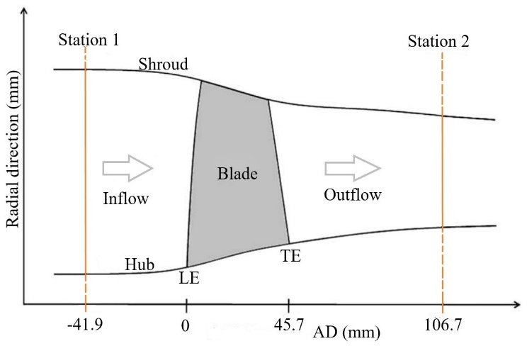
A high-pressure ratio axial compressor NASA rotor 37 is selected for the current research work. The details of the design specifications of the compressor rotor are given in Table 1, and the compressor specifications are taken from the AGARD report (Dunham, 1998). The rotational speed of the compressor rotor is 17188.7 revolution per minute and the rotor has 36 number of blades. The polytropic efficiency of the rotor is 88.9 % at 20.19 kg s−1 mass flow rate (design) and the total pressure ratio of the rotor is 2.106. The mass flowrate of the compressor rotor at choked condition is 20.93 kg s−1. The tip gap height of the compressor blade is 0.356 mm at 47 % span. The meridional plane of the rotor 37 is depicted in Fig. 1. Total temperature and total pressure are measured at station 1 (inlet) and it is connected to station 2 (outlet). The distance between the blade LE from station 1 is −41.9 mm, whereas station 2 is positioned 106.7 mm downstream from the blade TE close to the hub.

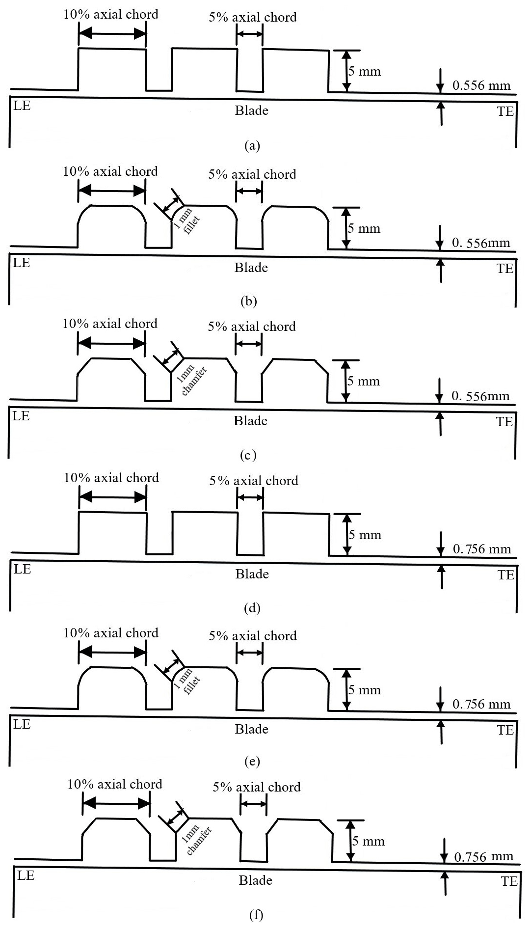
Three dissimilar circumferential grooves shapes with various tip gaps height for NASA rotor 37 are designed in the current research work to increase the performance and stability of the axial compressor rotor as depicted in Fig. 2. The performances and stabilities of all the models are compared with the smooth wall case and each other. There are total six different models and three grooves are installed in each model. The axial position of the grooves is started from eighteen percent to sixty-three percent of the blade chord. The tip gap height of the smooth wall casing is 0.556 mm. The tip gap height of the models 1–3 is 0.556 while the tip gap height of the models 4–6 is 0.756 mm. The shape of the grooves of model 1 is rectangular and the depth is 5 mm. The size of each groove covered the area of ten percent axial chord at the blade tip and the gap among each groove is five percent. Earlier researchers Huang et al. (2006) and Kim et al. (2013) researched on rectangular grooves depth width, and numbers to find the impacts of these three factors on the stall margin and efficiency of the transonic axial compressor. According to their report, the circumferential grooves could increase the performance and stable range of axial transonic compressor. Thus, in the current research work model, 1 is the basic model to discover the influence of circumferential grooves on the performances and stability of transonic compressor. All the models are depicted in Fig. 2. Model 2 and 5 have rectangular shape with fillet edges while model 3 and 6 have rectangular shape with chamfer edges. The length of the fillet and the chamfer edges is one millimetre each.
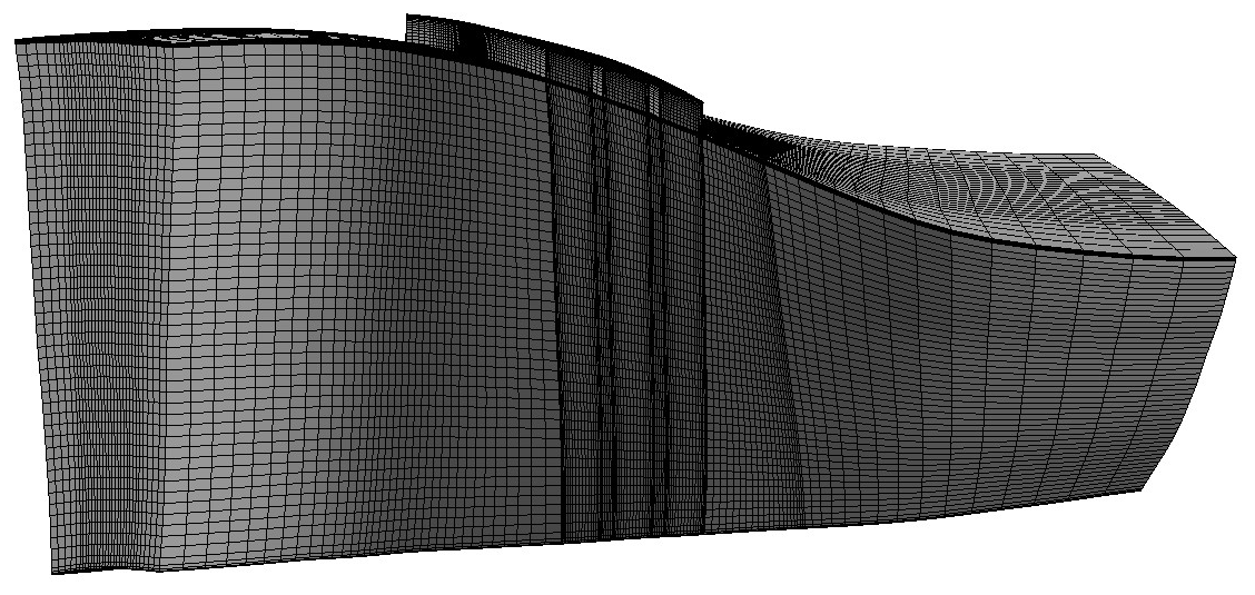
Commercial software ANSYS-CFX17 is used for all numerical simulations applying 3D steady governing equations in the current research work. The Reynolds averaged Navier Stokes three-dimensional equations are discretized with the help of finite volume technique. Computational grid software NUMECA Autogrid 5 (2009), ANSYS-CFX17 (2016) are used for the creation of blade geometry, generation of mesh, boundary condition description, numerical investigation, and post-process results. The Fluid domain and casing grooves are constructed in Ansys design modeler, whereas the structured mesh is created in Ansys ICEM CFD respectively. The computational domain of single blade passage considering periodic flow condition between two neighbouring rotor blades in the rotation of circumferential direction is used in the current research work simulation for the transonic compressor. To ensure the quality of the grid orthogonality, the structure grids of HOH topology are created for a single passage. The mesh computational grids are depicted in Fig. 3.
For structure grids, multi blocks H-O-H topology is adopted. The compressor blade LE and TE are constructed with O type structure grids, and H type structure grids are created in the other region. The inlet block and outlet blocks are constructed with and number of grids respectively. The tip gap height is constructed with number of grids. Each groove block is constructed with number of grids. For the current research work 4.45×10⁵ number of grids are chosen and the grid test is depicted in Fig. 4. Total pressure ratio and adiabatic efficiency for three cases with different number of grids are shown in Fig. 4. The total number of grids of the three cases are 2.22×10⁵, 4.45×10⁵ and 7.80×10⁵ respectively. It can be seen in Fig. 4 when the grid points are changed from 4.45×10⁵ to 7.80×10⁵, a small change occurred in the total pressure ratio and adiabatic efficiency. So, considering the cost and computational accuracy 4.45×10⁵ number of grids is selected for the current research work. For all simulations, the SST turbulence model is adopted. According to Bardina et al. (1997) for adverse pressure gradient separation the SST model is more appropriate for the flow analysis. The accuracy of the turbulent flow of the numerical computation firmly relies on the wall shear stress treatment. m is the minimum grid spacing on the solid walls to ensure the value of y+ minimum set below two for the first layer thickness to seizure the wall share stress correctly. This current research work selected ideal air gas as a working fluid. Fixed total pressure of 101 325 Pa and total temperature of 288.15 K at the inlet along with the flow angle. The turbulence intensity of five percent at the inlet boundary condition is also fixed. A periodic condition is applied for the blade passage. Adiabatic state with no-slip wall and smooth wall for the blade is chosen in the boundary condition details. The radial equilibrium state is applied at the outlet. Backpressure at the outlet is increased and set the radial equilibrium state condition to examine the static pressure radial distribution. Near to the stall limit, the backpressure of 50 Pa is increased. The point close to the stall limit is considered the last steady point. The grooves and the blade passage are linked with general grid interface technique. The convergence criteria which is proposed by Huang et al. (2006) are adopted in the current research work. The criterion states that for three hundred steps mass flow rate variation at the inlet is less than 0.001 kg s−1. The inlet and outlet mass flow rate variation is less than 0.5 %. The variation of adiabatic efficiency per hundred steps is less than 0.3 %. In this research work, the same convergence criterion is used numerically for the initiation of the stall.

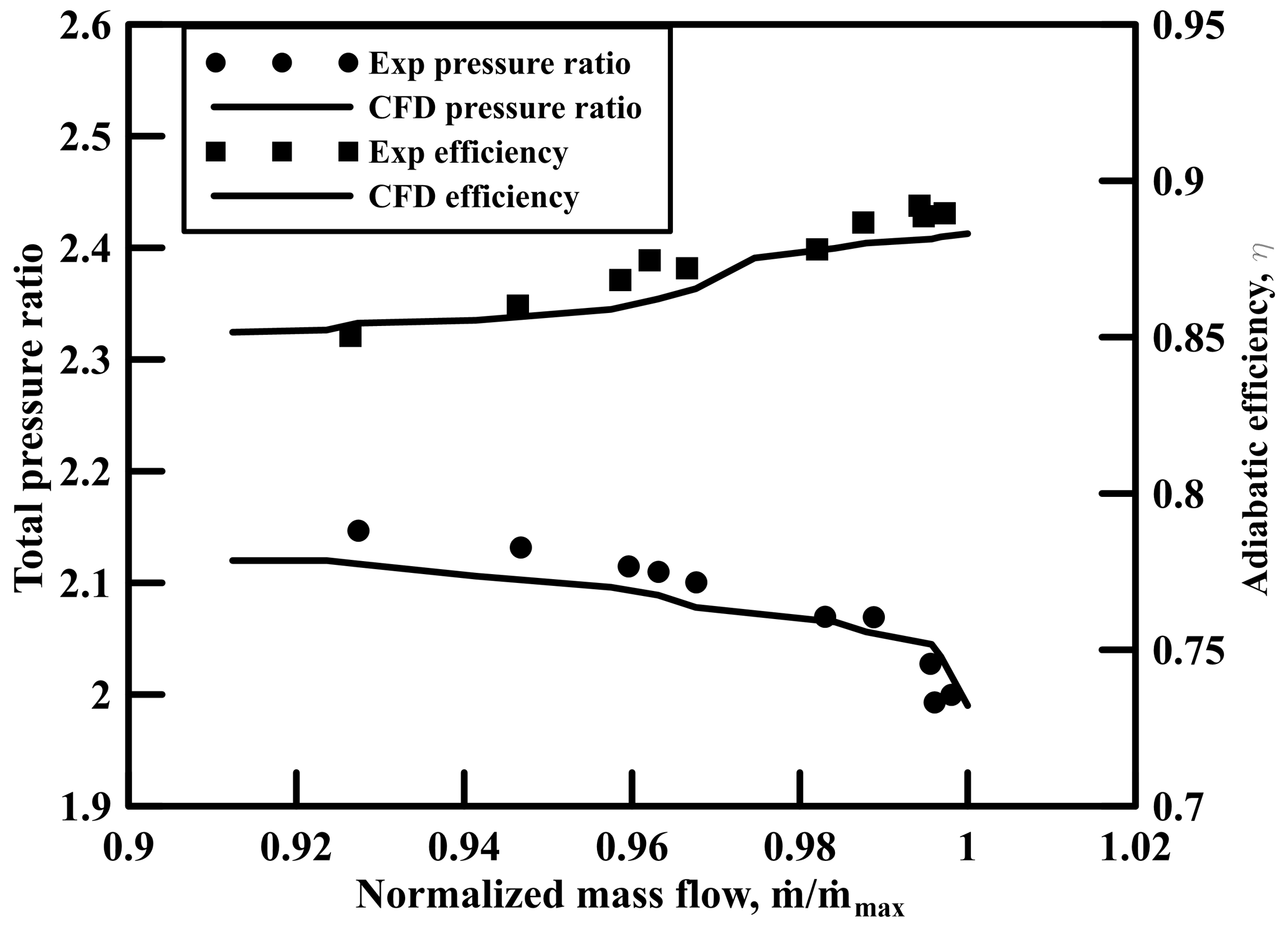
Firstly, single passage steady simulation is conducted on rotor 37 with normal casing for the validation of total pressure ratio and adiabatic efficiency. The simulation results are compared with the report of AGARD (Dunham, 1998). Both experimental and numerical results show good agreement for total pressure ratio and adiabatic efficiency, and the validation is depicted in Fig. 5. The technique of casing grooves is adopted to improve the stability and performance of the axial compressor.
Stall margin, stall margin improvement pressure ratio, and adiabatic efficiency are selected as parameters in the current research work to evaluate the performance and stability of the axial transonic compressor and the details of all the parameters as follows.
where PR is the pressure ratio and is the mass flow rate. The peak and stall subscripts signify mass flow rate and total pressure ratio at peak and near to stall condition respectively. γ, Pt and Tt denote specific heat ratio, total pressure ratio, and total temperature ratio respectively.
The loading distribution of the axial compressor rotor blade near to stall condition at 98 % span for smooth casing and models 1–6 is depicted in Fig. 6. The pressure difference is observed between the pressure and suction surface of the compressor blade in the grooves installation the region. There have two substantial impacts occurred with the installation of circumferential grooves. First the fluctuation of the pressure on the pressure surface which caused the local pressure to increase like a wave pattern. Secondly the shockwave downward movement, which is observed from the pressure distribution on the blade suction surface, most probably gives an advantage to the stability of the compressor. This signifies that fixing the grooves increased the blade loading and the shockwave advance to the passage due to which the pressure ratio is increased and the flux ratio is decreased at the stall point. With the increased of the tip gap height, the pressure gradient near the blade leading edge increased. The increased pressure gradient led to tip leakage flow (TLF) over the rotor blade at large tip gap height and resulting in the tip vortex at the compressor blade tip. The tip clearance flow angle is different for every model near to the leading-edge, while the rare part shows the same pattern because no groove is installed at the rear part. More pressure difference is observed in model 4 in Fig. 10 in the location of grooves installation. It is concluded that increased tip gap height lead to more tip leakage flow due to tip vortex.

Figure 6Distribution of streamwise pressure at 98 % span (near stall condition) for smooth casing and all models.
The contours of entropy for smooth casing and models 1–6 are shown in Fig. 7 at 98 % span close to stall point. Figure 7 demonstrates that models 1–6 have high entropy value at the tip of the compressor blade. All the models displayed minimum values of entropy in the downstream zone with the installation of the circumneutral grooves apart from the smooth casing and similar results is reported by Mao et al. (2018). The entropy reduction demonstrated the improvement of the structure of the tip leakage vortex. The value of entropy is minimum in models 1–6 after sixty five percent of the blade chord owing no groove is fixed in downstream zone to deal with the TLV. With the installation of circumferential grooves, the efficiency in the low mass region is recovered due to the initiation of entropy lower value. Also, in Fig. 7 the entropy lower value can be seen for other models in the downstream region but the TLV structure is much enhanced for model 1. The tip gap height of models 1–3 is 0.556 mm while the tip gap height of models 4–6 is 0.756 mm. When the tip gap height is small more efficiency is recovered in the lower region however, when the tip gap height is large less efficiency is recovered in the lower region. TLV got more strength for a large tip gap height in the lower zone. According to author, the efficiency is recovered for all models where more efficiency is recovered for models 1–3 due to small tip gap height. Among all the models 1–6 and smooth casing, model 1 were found to be more effective and efficient model. This shows that model 1 is the most efficient model among all the models and it gives higher stall margin than the other models due to enhanced TLV structure in the region of low mass area and added more efficiency.
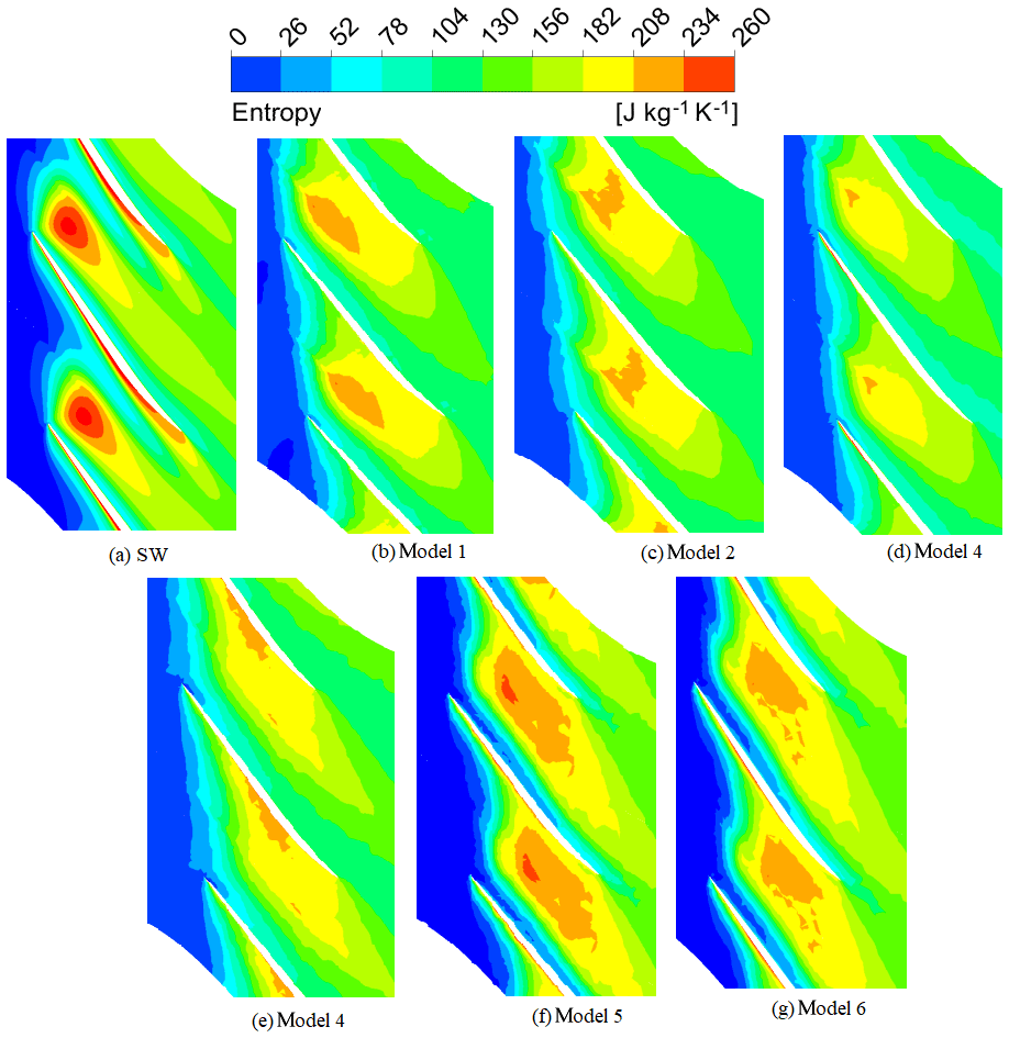
Figure 7The contours of entropy for smooth casing and models 1–6 at 98 % span close to the stall point.
Contours of axial velocity for smooth casing and models 1–6 at 98 % span close to stall point are shown in Fig. 8. In axial transonic compressor when the mass flowrate is decreased, the TLV interaction intensity with the shock wave is augmented which advanced to a low-speed region in the downstream and energy loss is observed in the passage shock. The region of low-speed energy is called the vortex stagnation zone, and this zone varies the path of the main flow by increasing the pressure from the backward side. Therefore, the velocity of flow is reduced and caused separation in the flow. This vortex stagnation region could be minimized with the help of fixing the circumferential grooves on the axial compressor shroud. This demonstrates that circumferential grooves are more beneficial for improving the operating range and stability of the axial compressor. Figure 8b depicts that vortex stagnation which is much improved in model 1 then the other models because the rectangular grooves of model 1 are more proficient to decrease the blockage area. It is concluded that model 1 is the best model in terms of stability and operating range as compared to the other two models. While model 5 in Fig. 8f is less enhanced than the other models. However, when the tip gap height is increased less enhancement appeared in the vortex stagnation zone and blockage area. The tip gap height of models 1–3 is 0.556 mm while the tip gap height of models 4–6 is 0.756 mm. Moreover, more improvement comes in the blockage area and vortex stagnation zone with the small tip gap height. So, the first three models show more enhancement to the blockage zone. As shown in Fig. 8b model 1 is more improved model then all the other models due to more improvement in the vortex stagnation region and decreased blockage zone. So, Model 1 is the most proficient model among all the models in Fig. 8 due to much improved stall margin. Axial velocity in Fig. 8a has the higher value at the tip of the blade after mid-chord whereas, different pattern is observed in all others models which shows the enhancement in performance and the stall margin of the axial compressor.
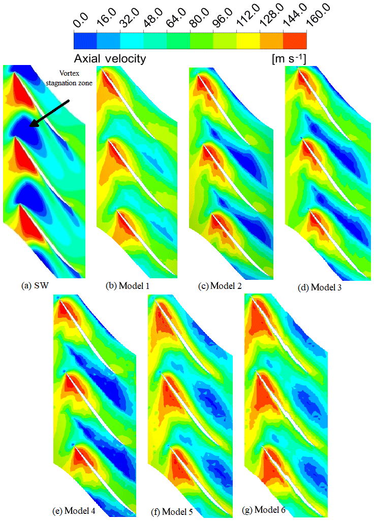
Figure 8The contours of Axial velocity for smooth casing and models 1–6 at 98 % span close to stall point.
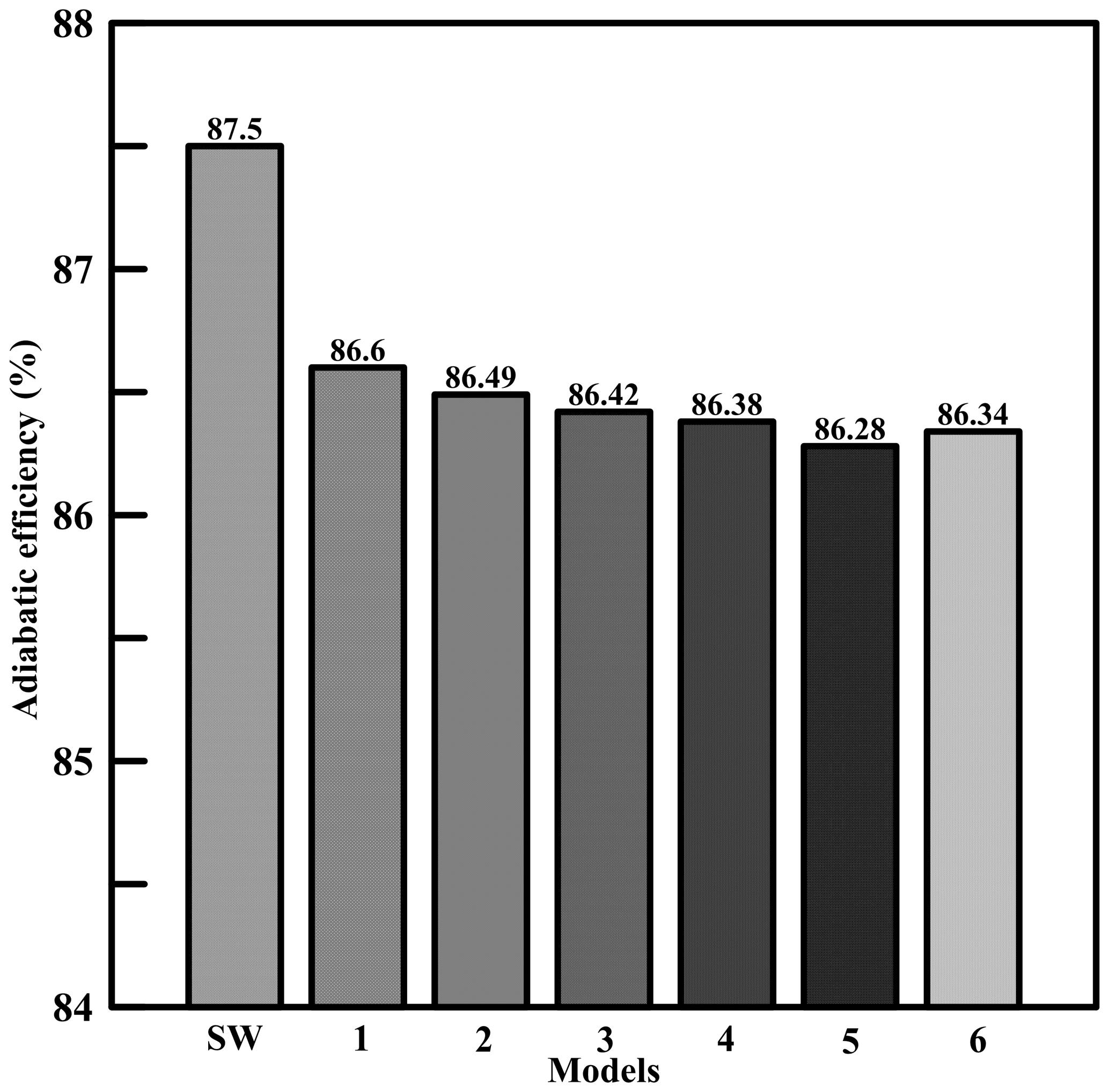
The adiabatic efficiency for smooth casing and models 1–6 is depicted in Fig. 9. The peak adiabatic efficiency for all models is slightly decreased with the installation of circumferential grooves. The smooth casing has a maximum efficiency of 87.5 % (0.556 mm tip gap height). The efficiencies of models 1–6 are found to be 86.6 %, 86.49 %, 86.42 %, 86.38 %, 86.28 % and 86.34 % respectively. The efficiencies of models 1–6 are reduced by 0.9 %, 1.01 %, 1.08 % 1.12 %, 1.22 % and 1.16 % respectively. So, the efficiency difference between the smooth casing and all the models is small, and this efficiency is greater than the efficiency reported by Kim et al. (2013) for all the models. The axial position of the grooves started from eighteen to sixty three percent. The tip gap height of the first three models is 0.556 mm and the tip gap height of the last three models is 0.775 mm. According to the author when the tip gap height is increased, the peak adiabatic efficiency is reduced. Among all the models, model 1 gave the highest adiabatic efficiency and it is the most efficient model. The stall margin for smooth casing and models 1–6 is depicted in Fig. 10. Model 1 has the highest stall margin among all the models and model 5 gave less stall margin but the stall margin of model 5 was higher than that of the smooth casing. The stall margin of models 1–6 is found to be 16.85 %, 14.98 %, 14.62 %, 14.21 %, 14.15 % and 14.52 % respectively. The stall margin of model 1 is enhanced by 4.39 % while the stall margin of models 2–6 is improved by 2.52 %, 2.16 %, 1.75 %, 1.69 % and 2.06 % respectively. Thus, all the models have positive and good impact on the stall margin and stability of the axial compressor. It is believed that the stall margin improvement decreased when the tip gap height is increased.

The influence of three grooves with various shapes and tip gap height using 3D RANS equations on the adiabatic efficiency and stall margin is investigated numerically in the current research work. The following noteworthy and significant outcomes are drawn from the current research work.
-
The difference of pressure between the suction surface and the pressure surface at the blade tip region caused tip clearance flow growth. With the increase of the tip gap height, the tip clearance flow closed to the shroud is improved that caused energy loss.
-
The vortex stagnation region is reduced with the installation of the circumferential grooves. The tip clearance flow is minimized with the help of grooves which gave advantage to a decreased vortex stagnation region.
-
The performance of the transonic axial compressor with small tip gap height CGCT is found better than the large tip gap height CGCT.
-
The total pressure, stall margin and peak adiabatic efficiency of the transonic axial compressor with several grooves shape decreased with the large tip gap height CGCT. Thus, the overall performance of the transonic axial compressor is reduced.
-
The magnitude and strength of the tip leakage vortex of the transonic axial compressor with different grooves shape and enlarge tip gap height is increased. The tip leakage vortex with a small tip gap height is cameback to the similar direction after passing through the main flow region, while with a large tip gap height, the vortex separation occurred on the pressure surface of the transonic axial compressor blade.
-
The axial compressor performance and stability are changed with various types of grooves shape and tip gap height. So, compared all the three types of grooves, the rectangular grooves gave the best performance and the grooves with fillet shape gave better performance than chamfer shape grooves in term of stall margin and adiabatic efficiency.
-
The enhancement of the flow field for fillet and chamfer grooves model is noticed at the rotor blade tip from entropy and axial velocity contours. The installation of fillet and chamfer types grooves supress the tip leakage flow, which helped to enhance the stable range and performance of the axial compressor.
-
The maximum adiabatic efficiency and stall margin are achieved with rectangular grooves shape (0.556 mm tip gap height) and the maximum adiabatic efficiency and stall margin of the rectangular grooves are 86.6 % and 16.68 % respectively.
-
The peak adiabatic efficiency slightly decreased with the installation of circumferential grooves. Due to corner separation, entropy is generated which combined with reverse tip leakage flow which decreased the peak adiabatic efficiency of the transonic axial compressor.
Data can be made available upon reasonable request.
NA proposed and developed the overall concept of the paper, conducted numerical simulations and written the major paper. QZ and JB supervised and structuring the process of the paper. HM helped in making figures. TY checked the writing language. SAA helped in writing language.
The authors declare that they have no conflict of interest.
The authors wish to thank the support of National Natural Science Foundation of China (No. 51809065 and 51741901), and the Ph.D. Student Research and Innovation Fund of the Fundamental Research Funds for the Central Universities (Grant No. 3072019GIP0304).
This research has been supported by the National Natural Science Foundation of China (grant nos. 51809065 and 51741901)
This paper was edited by Hui Ma and reviewed by Gambo dayyabu kofar bai and one anonymous referee.
ANSYS CFX-17.0.0: ANSYS CFX-Solver Theory Guide, Release, ANSYS Inc., 2016.
Bardina, J. E., Huang, P. G., and Coakley, T. J.: Turbulence modeling validation, testing, and development, 28th Fluid Dynamics Conference, https://doi.org/10.2514/6.1997-2121, 1997.
Beheshti, B. H., Teixeira, J. A., Ivey, P. C., Ghorbanian, K., and Farhanieh, B.: Parametric study of tip clearance – casing treatment on performance and stability of a transonic axial compressor, J. Turbomach., 126, 527–535, https://doi.org/10.1115/1.1791643, 2004.
Chen, H., Huang, X., and Fu, S.: CFD investigation on stall mechanisms and casing treatment of a transonic compressor, 42nd AIAA/ASME/SAE/ASEE Joint Propulsion Conference & Exhibit, https://doi.org/10.2514/6.2006-4799, 2006.
Choi, M.: Effects of circumferential casing grooves on the performance of a transonic axial compressor, Int. J. Turbo Jet Eng., 32, 361–371, https://doi.org/10.1515/tjj-2015-0001, 2015.
Dinh, C.-T., Heo, M.-W., and Kim, K.-Y.: Aerodynamic performance of transonic axial compressor with a casing groove combined with blade tip injection and ejection, Aerosp. Sci. Technol., 46, 176–187, https://doi.org/10.1016/j.ast.2015.07.006, 2015.
Dunham, J.: CFD validation for propulsion system components, AGARD advisory report no. 355, Advisory Group on Aerospace Research and Development, North Atlantic Treaty Organization 1998, ISBN 92-836-1075 X, 1998.
Furukawa, M., Inoue, M., Saiki, K., and Yamada, K.: The role of tip leakage vortex breakdown in compressor rotor aerodynamics, J. Turbomach., 121, 469–480, https://doi.org/10.1115/1.2841339, 1999.
Furukawa, M., Saiki, K., Yamada, K., and Inoue, M.: Unsteady flow behavior due to breakdown of tip leakage vortex in an axial compressor rotor at near-stall condition, ASME turbo expo Power for land, sea, and air, American Society of Mechanical Engineers Digital CollectionMunich, Germany, Vol. 1, https://doi.org/10.1115/2000-GT-0666, 2000.
Hembera, M., Kau, H.-P., Danner, F., Butzeck, C., and Johann, E.: Development of circumferential grooves for axial compressors based on flow mechanisms, 44th AIAA/ASME/SAE/ASEE Joint Propulsion Conference & Exhibit, https://doi.org/10.2514/6.2008-4988, 2008.
Houghton, T. and Day, I.: Stability enhancement by casing grooves: the importance of stall inception mechanism and solidity, J. Turbomach., 134, 2383–2391, https://doi.org/10.1115/1.4002986, 2012.
Huang, X., Chen, H., Shi, K., and Fu, S.: An analysis of the circumferential grooves casing treatment for transonic compressor flow, Science China Physics, Mech. Astron., 53, 353–359, https://doi.org/10.1007/s11433-010-0123-0, 2010.
Hwang, Y. and Kang, S.-H.: Numerical study on near-stall flow unsteadiness in an axial compressor with casing treatment, J. Mech. Sci. Technol., 27, 2375–2381, https://doi.org/10.1007/s12206-013-0622-9, 2013.
Kim, J. H., Kim, K. Y., and Cha, K. H.: Effects of number of circumferential casing grooves on stall flow characteristics of a transonic axial compressor, Appl. Mech. Mater., 284–287, 727–732, https://doi.org/10.4028/www.scientific.net/AMM.284-287.727, 2013.
Legras, G., Gourdain, N., and Trebinjac, I.: Numerical analysis of the tip leakage flow field in a transonic axial compressor with circumferential casing treatment, J. Therm. Sci., 19, 198–205, https://doi.org/10.1007/s11630-010-0198-y, 2010.
Li, J., Geng, S., Du, J., Zhang, H., and Nie, C.: Circumferentially propagating characteristic dominated by unsteady tip leakage flow in axial flow compressors, Aerosp. Sci. Technol., 85, 529–543, https://doi.org/10.1016/j.ast.2018.11.058, 2019.
Mao, X., Liu, B., Tang, T., and Zhao, H.: The impact of casing groove location on the flow instability in a counter-rotating axial flow compressor, Aerosp. Sci. Technol., 76, 250–259, https://doi.org/10.1016/j.ast.2018.01.037, 2018.
Muller, M. W., Biela, C., Schiffer, H.-P., and Hah, C.: Interaction of rotor and casing treatment flow in an axial single-stage transonic compressor with circumferential grooves, ASME Turbo Expo: Power for Land, Sea, and Air, 6, 67–78, https://doi.org/10.1115/GT2008-50135, 2008.
NUMECA International IGG v8.9-1 and Autogrid5 v8.9-1, User Manual, NUMECA International, Brussels, 2009.
Smith, G. and Cumpsty, N.: Flow phenomena in compressor casing treatment, J. Eng. Gas Turb. Power, 106, 532–541, https://doi.org/10.1115/1.3239604, 1984.
Song, W., Zhang, Y., and Chen, H.: Design and Optimization of Multiple Circumferential Casing Grooves Distribution Considering Sweep and Lean Variations on the Blade Tip, Energies, 11, 2401, https://doi.org/10.3390/en11092401, 2018.
Taghavi-Zenouz, R. and Eslami, S.: Effects of casing treatment on behavior of tip leakage flow in an isolated axial compressor rotor blade row, J. Chin. Inst. Eng., 36, 819–830, https://doi.org/10.1080/02533839.2012.747058, 2013.
Thompson, D. W., King, P. I., Hah, C., and Rabe, D. C.: Experimental and computational investigation of stepped tip gap effects on the flowfield of a transonic axial-flow compressor rotor, ASME International Gas Turbine and Aeroengine Congress and Exhibition, Exhibition, Vol. 1, Paper No: 97-GT-524, V001T03A107; 19 pp., https://doi.org/10.1115/98-GT-090, 1998.
Wisler, D.: Loss reduction in axial-flow compressors through low-speed model testing, Transactions of the ASME, J. Eng. Gas Turb., 107, 354–363, https://doi.org/10.1115/1.3239730, 1985.
Wu, Y., An, G., and Wang, B.: Numerical investigation into the underlying mechanism connecting the vortex breakdown to the flow unsteadiness in a transonic compressor rotor, Aerosp. Sci. Technol., 86, 106–118, https://doi.org/10.1016/j.ast.2018.12.040, 2019.
Zhang, Q., Du, J., Li, Z., Li, J., and Zhang, H.: Entropy Generation Analysis in a Mixed-Flow Compressor with Casing Treatment, J. Therm. Sci., 28, 915–928, https://doi.org/10.1007/s11630-019-1206-5, 2019.
Zhang, Y., Lu, X., Chu, W., and Zhu, J.: Numerical investigation of the unsteady tip leakage flow and rotating stall inception in a transonic compressor, J. Therm. Sci., 19, 310–317, https://doi.org/10.1007/s11630-010-0388-7, 2010.
Zhou, X., Zhao, Q., Xiang, X., and Cui, W.: Investigation of groove casing treatment in a transonic compressor at different speeds with control volume method, P. I. Mech. Eng. G-J. Aer., 230, 2392–2408, https://doi.org/10.1177/0954410015625666, 2016.
Zhou, X., Zhao, Q., Cui, W., and Xu, J.: Investigation on axial effect of slot casing treatment in a transonic compressor, Appl. Therm. Engin., 126, 53–69, https://doi.org/10.1016/j.applthermaleng.2017.07.165, 2017.
Zhu, W., Cai, L., Wang, S., and Wang, Z.: Numerical Investigation of Circumferential Groove Casing Treatment in a Highly-Loaded Low-Reaction Transonic Compressor Rotor, J. Therm. Sci., 1–12, https://doi.org/10.1007/s11630-019-1180-y, 2019.