the Creative Commons Attribution 4.0 License.
the Creative Commons Attribution 4.0 License.
 | 12 May 2020
Research on a medium-tracked omni-vehicle
Yunan Zhang
Nianyu Li
Yinghui Shang
Existing omnidirectional vehicles have disadvantages of poor load capacities and practicability. Based on the omnidirectional mobile track and an adapted symmetrical layout, a novel medium-tracked omni-vehicle was designed. The kinematic and dynamic model of the vehicle was established, and the anisotropy of the velocity and acceleration of the vehicle was analyzed. With a counterbalanced forklift as the design goal, a virtual prototype and real prototype of the vehicle were established. The prototype had a no-load weight of 5 t and a full-load weight of 7 t. Simulations and experiments were carried out for various omnidirectional movements of the prototype, such as longitudinal, lateral, multi-angle diagonal, and center-point steering motions. The simulation and experimental results showed that the vehicle performed omnidirectional motion in the plane under no-load and full-load conditions. The translational motion of the prototype exhibited anisotropic motion. The causes of the trajectory and velocity deviation during the motion of the prototype were analyzed.
- Article
(11355 KB) - Full-text XML
- BibTeX
- EndNote


Omnidirectional mobile robots (vehicles) have always been a popular topic in the field of robot research. An omnidirectional mobile robot is a robot that can move in any direction on the plane at any time without considering the speed limit of the driving motor (Zhao and Yi, 2010). According to different omnidirectional running mechanisms, omnidirectional vehicles can be divided into wheeled and tracked omnidirectional vehicles. In the above classification, the universal wheel (Yang et al., 2018; Clavien et al., 2018; Cao, 2018), the omnidirectional mobile robot in a single sphere form (Madhushani et al., 2017; Karavaev and Kilin, 2017), and the omnidirectional flexible robot (Pan et al., 2019) are not included.
Wheeled omnidirectional vehicles are characterized by the scale application of Mecanum wheels (Wang, 2018; Peng et al., 2016). The shortcomings of Mecanum wheels are known (Zhang, 2018). With the wear of the roller, the circular outer surface of the wheel is destroyed, and a severe “ground impacting” phenomenon occurs. Meanwhile, the vibrations increase, which affects the handling and precision of the motion.
Other typical wheeled omnidirectional running mechanisms are as follows. Alternate wheels (Park et al., 2016) are generally used in the motion control research of small robots, similar to the Transwheel (Sheikhlar et al., 2016). The MY wheel series (one to three generations) was studied by Ye et al. (2016) and Tong (2017) in series and parallel forms, and a small cylindrical AGV (automated guided vehicle) was developed (Ye et al., 2016; Tong, 2017). Ball wheels (West and Asada, 1997) have remained in the research stage and have few practical applications. The Omni-Ball was studied by Tadakuma et al. (2009a), who developed a small tetrahedral deformable omnidirectional spherical robot for disaster rescue purposes (Tadakuma et al., 2009b). The structure and design of this wheeled omnidirectional mobile mechanism are similar to the Omni-crawler that will be introduced below. Tadakuma et al. (2004) developed the Vmax-carrier2, a small omnidirectional vehicle, which is also known as Vuton-II (Tadakuma et al., 2004). In plane motion, the Vmax-carrier2 has a large number of discs landing on the ground simultaneously, so the movement is stable and has a certain obstacle-crossing ability.
The common disadvantages of wheeled omnidirectional running mechanisms are as follows: poor load capacities, high requirements on the smoothness and cleanliness of the motion environment, and poor off-road and obstacle-crossing performances. One way to solve these problems is to develop tracked omnidirectional vehicles. Research on tracked omnidirectional vehicles began late. Typical tracked omnidirectional running mechanisms include the omnidirectional spherical tire crawler (Isoda et al., 1997) and the omnidirectional crawler with free rollers (Chen et al., 2002). These mechanisms have been in the research stage without any practical application. The Vuton crawler (Roh et al., 2013) consists of a series of cylindrical rollers that can rotate freely about their own axes. This mechanism was used to develop a small omnidirectional vehicle, Vuton-I, and a single-person earthquake simulation seat. The omnidirectional track (Mortensen Ernits et al., 2017) used a combination of Mecanum rollers and traditional tracks. The authors used it to build an obstacle-crossing and omnidirectional vehicle, without any experimental research. The omnidirectional mobile track (Zhang et al., 2017) was used to develop a prototype of a light-tracked omnidirectional vehicle (Zhang and Huang, 2015; Zhang et al., 2017). The Omni-crawler was used to build a small omnidirectional vehicle (Tadakuma et al., 2009a), and centimeter-level obstacle-crossing experiments were conducted. The Omni-crawler was extended to robot fingers (Tadakuma et al., 2012), pipeline robots (Singh et al., 2017), and other applications. There are other tracked omnidirectional running mechanisms, such as the planar omnidirectional crawler mobile mechanism (Tadakuma et al., 2017).
The omnidirectional vehicles described above only required omnidirectional mobility and simple obstacle-crossing capabilities, and the carrying capacity was not considered. Compared with wheeled omnidirectional vehicles, tracked omnidirectional vehicles have been improved in terms of unstructured road mobility and operational capabilities, but their performances are still unsatisfactory. How to develop a practical medium or heavy-duty omnidirectional vehicle with a high reliability and high load-carrying capacity has become a main research area and difficulty in this field.
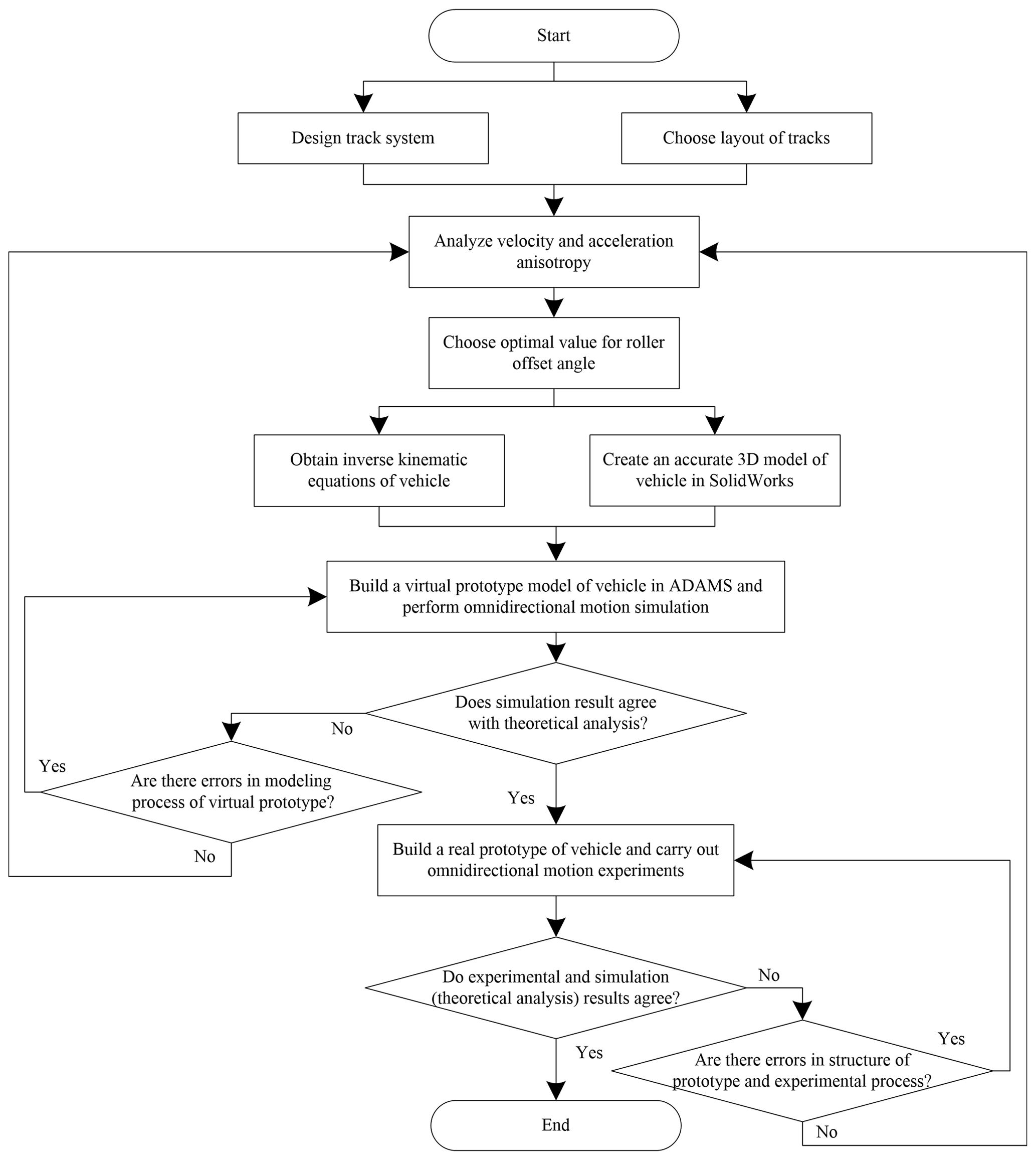
To resolve the problems described above, based on the research of omnidirectional mobile tracks, a novel medium-tracked omnidirectional vehicle is proposed in this paper. We designed and patented a track system (Zhang and Fang, 2019a) (CN110329375A) and track shoe unit (Zhang and Fang, 2019b) (CN110395324A) with a stronger load capacity, as shown in Fig. 1a and b. The kinematic and dynamic equations were established. We used the simplified maximum–minimum method to analyze the motion anisotropy, and we provided the relevant properties and proofs. Based on the design standards for counterbalanced forklifts (Tao and Wei, 2010), virtual and real prototypes were established. The motion simulation and experiments were performed using a vehicle with no load (5 t) and full load (7 t). The simulation and experimental data were analyzed and compared with the theoretical results, and the motion laws of large-scale, heavy-duty tracked omnidirectional mobile platforms were summarized. The research and design procedure is summarized as a flowchart in Fig. 2.

The structure and layout of the track determine the omnidirectional movement capabilities of the tracked omni-vehicle. Aiming at the characteristics of a large size and heavy load of the medium-tracked omni-vehicle, the structure of the track was modularized, and the optimal layout of the track was selected.
2.1 Track system and track shoe unit structure
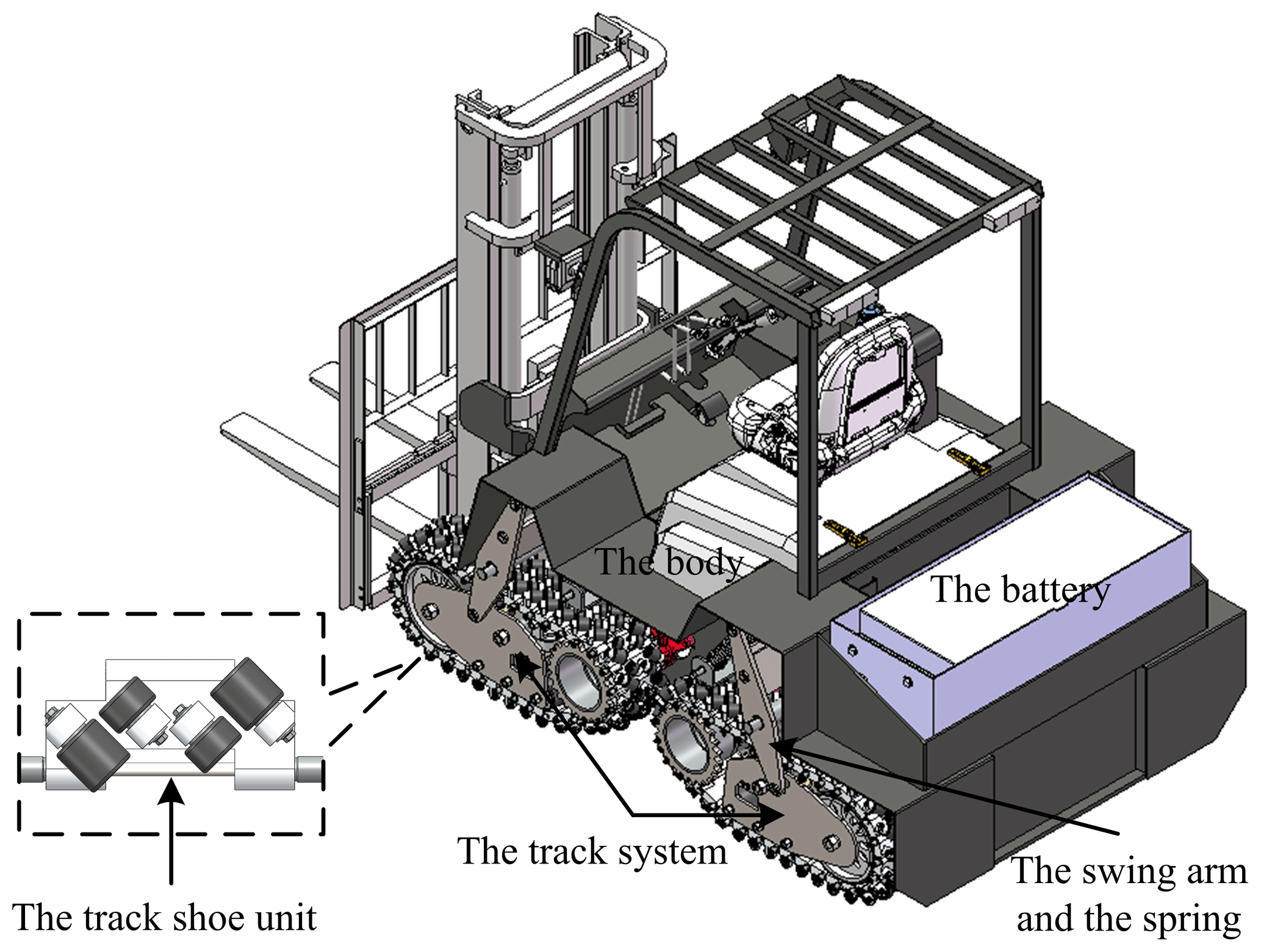
The medium-tracked omni-vehicle was designed with a modular structure, which was composed of a vehicle body and several track systems. The track system consisted of track shoe units, a driving sprocket, a support roller, a tensioning mechanism, an idler, road wheels, and other components, as shown in Fig. 1a. The track shoe unit was composed of a track plate, roller seats, rollers, and a track pin, as shown in Fig. 1b.
As shown in Fig. 1b, the angle between the roller axis and the track pin axis is defined as , and α is defined as the roller offset angle. If α is ±90∘, the omnidirectional mobile track will degenerate into an omnidirectional crawler with free rollers (Chen et al., 2002).
In a previous report (Zhang and Huang, 2015), the authors analyzed the motion relationship between the track and the vehicle. The inverse kinematic equations of the vehicle are as follows:
where , vx is the translational velocity of the vehicle along the x axis, vy is the translational velocity of the vehicle along the y axis, ωz is the center-point steering angular velocity of the vehicle, ωi is the angular velocity of the driving sprocket, ri is the pitch radius of the driving sprocket, νi is the angular velocity of the roller at the center point of the ground contact segment of the track, αi is the offset angle of the roller, βi is the angle between the center of the track and the center of the vehicle, li is the distance between the center of the track and the center of the vehicle, and θi is the angle between the coordinate system of the track and the coordinate system of the vehicle. The subscript i represents the ith track, where .
The necessary condition for the vehicle to realize omnidirectional motion is that the velocity inverse Jacobian matrix Jω of the system is full rank, i.e., rank(Jω)=3. In this case, the system does not have a singular configuration.
2.2 Layout of tracks in medium-tracked omni-vehicle
The layout of the omnidirectional running mechanism directly determines whether a vehicle has the ability to move in all directions in the plane and affects the motion anisotropy of the vehicle. The “four-track concentric type (diamond layout)” and the “four-track longitudinal symmetrical type (rectangular layout)” are two kinds of layouts that are common and convenient for steering in omnidirectional running mechanisms. The following points must be considered when choosing a layout.
-
The vehicle should have a certain versatility with ordinary wheeled and tracked vehicles, which is conducive to the transition from existing non-omnidirectional vehicles to omnidirectional vehicles.
-
The layout should be easy to understand and accept by drivers and operators.
-
The layout should be highly scalable.
In conclusion, the longitudinal symmetrical layout was selected for the medium-tracked omnidirectional vehicle, as shown in Fig. 3.
A general inverse kinematics equation of the vehicle with a longitudinally symmetric layout was established. Based on this, the velocity and acceleration anisotropy were analyzed. Based on the anisotropy, the optimal value of the roller offset angle α and the inverse kinematics equation for the medium-tracked omni-vehicle were obtained.
3.1 Kinematic equation and velocity anisotropy
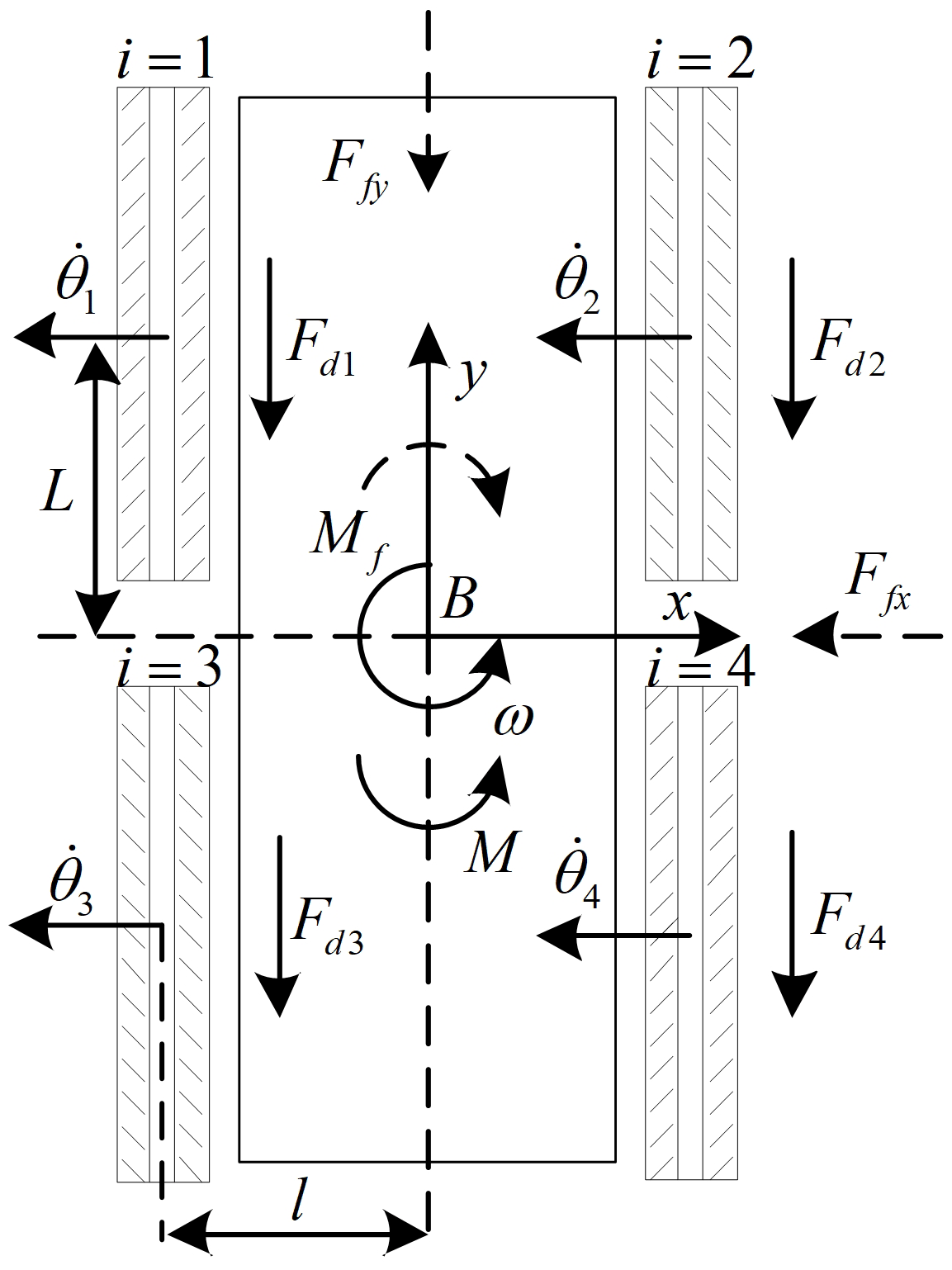
Figure 3 shows the top view of the medium-tracked omni-vehicle. The direction of the arrow on the x axis and the direction of the arrow on the y axis are positive directions. The counterclockwise direction is the positive direction of the center-point steering motion. The track is numbered in Fig. 3. Rollers of the ground contact segment are replaced by straight-line segments. is defined as the generalized velocity of the vehicle, and is defined as the angular velocity of the four tracks (four drive sprockets). These directions conform to the right-hand rule. L represents half of the distance between the center of the front track and the center of the rear track, l represents half the distance between the center of the left track and the center of the right track, and ri=R. According to Eq. (1), the inverse kinematical equation of the vehicle is
The velocity inverse Jacobian matrix Jω is full rank, i.e., rank(Jω)=3. Therefore, the vehicle had the ability to complete omnidirectional motions in the plane.
The vehicle is allowed to perform only translational motions. The angle between the driving direction of the vehicle and the horizontal x axis of the ground coordinate system is defined as ψ (ψ∈[0 2π)), and thus
where v is the velocity of the vehicle.
According to Eq. (3),
where jixjiy∈J, , and . Letting , i.e., the maximum linear velocity of each driving sprocket is 1 m s−1, then
There is no coupling relationship between and α or ψ. When α is constant, the following formula holds:
After simplification, . When or , there is a constant equation . The maximum translational velocity of the vehicle is the same in the vertical direction, and the value is 1 m s−1, which is verified by the curve shown in Fig. 4.
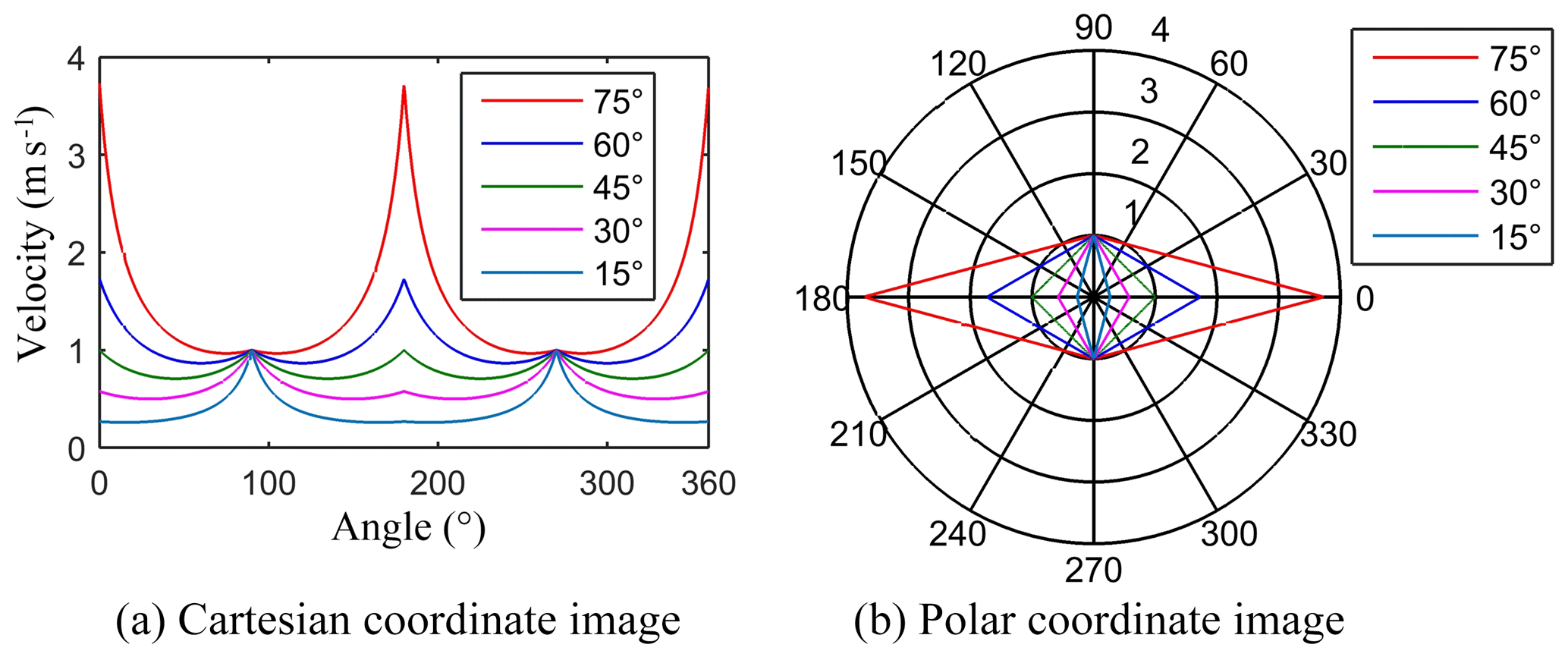
Considering , the maximum translational velocities in ψ were plotted, as shown in Fig. 4a and b. The polar coordinate system curve image is a regular parallelogram, which is symmetric along the line where () and is centrosymmetric. As the value of α increases, the corresponding quadrilateral curve gradually changes from narrow to flat. Further research showed that the above characteristics are directly related to the layout of omnidirectional running mechanisms and are universal. According to Fig. 4 and Eq. (4), the range of the maximum translational velocity decreases with the increase in α. To obtain the widest translational velocity, α should be as small as possible.
3.2 Dynamical equation and acceleration anisotropy
In a previous report (Zhang et al., 2017), the authors studied the single-track traction characteristics of a tracked omnidirectional vehicle.
When the single track moves vertically, i.e., or , the traction force is
In other directions, the traction force is
Fdi is the driving force applied to the roller (track) by the ith driving sprocket, and fqiy and fqix are the component forces applied to the roller by the ground along the x and y axes of the coordinate system, respectively.
The force analysis is shown in Fig. 3. Ffy is the motion resistance of the vehicle in the y direction, Ffx is the motion resistance of the vehicle in the x direction, Mf is the center-point steering motion resistance torque of the vehicle, and M is the center-point steering traction torque.
Considering the overall four-track system, the dynamical equation of the vehicle is obtained. and are the acceleration of the vehicle moving along the x and y axes, respectively, and is the angular acceleration of the vehicle during center-point steering motion. When or ,
and when and ,
where , m is the total mass of the vehicle, and I is the moment of inertia of the vehicle.
Referring to the analysis presented in Sect. 2.1, the vehicle is allowed to only perform translational motion. According to Eqs. (7) and (8), and neglecting the resistance, the following equation is obtained:
where ai is the acceleration provided by the ith driving sprocket, |ai|≤1, a is the acceleration of the vehicle, and gix and giy∈G, .
According to Eq. (9), is always established. When ψ2=0 or π, is always established, and the maximum value is . The above analysis showed that there is complementarity and duality in the translational maximum acceleration of the vehicle, which is verified by the curves shown in Fig. 5.
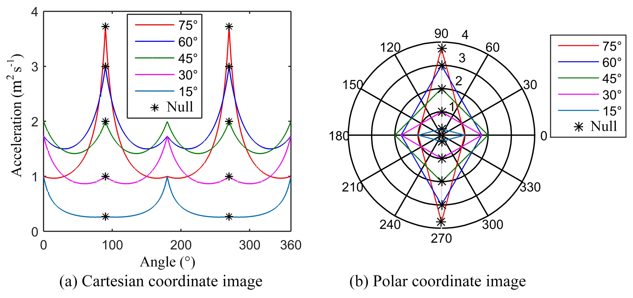
Considering , curves of the maximum translational acceleration of the vehicle in ψ were obtained, as shown in Fig. 5a and b. The values of the curves at and were null. As shown by Eq. (8), the corresponding maximum value was 4, which was independent of α. If the null values of each curve at and are ignored (which is equivalent to assuming that there is no static state of the rollers), the polar coordinate curve image is a regular parallelogram. This parallelogram is symmetric along the line where and is centrosymmetric. As the value of α increases, the corresponding quadrilateral curve gradually changes from flat to narrow. The above characteristics are directly related to the layout of omnidirectional running mechanisms and are universal. According to Fig. 5 and Eq. (8), when , the lateral acceleration of the vehicle is the largest, and the distribution of the maximum translational acceleration is the most balanced.
Combining the maximum translational velocity and acceleration anisotropy equation, the torque ratio formula of the translational motion of the vehicle was derived. Letting , the following equation holds:
where T1 and T2 are the sums of torques of the four driving sprockets in the first and second translational motions, respectively.
Considering the maximum translational velocity anisotropy and the maximum translational acceleration anisotropy of the vehicle, setting is a relatively optimal solution. At this point, the vehicle has the most balanced motion performance. With , the inverse kinematic equations of the vehicle are obtained as follows:
We designed and built a simplified virtual prototype of the medium-tracked omni-vehicle and performed omnidirectional motion simulations using the virtual prototype. The velocity anisotropy of the virtual prototype was analyzed using the simulation data.
4.1 Virtual prototype
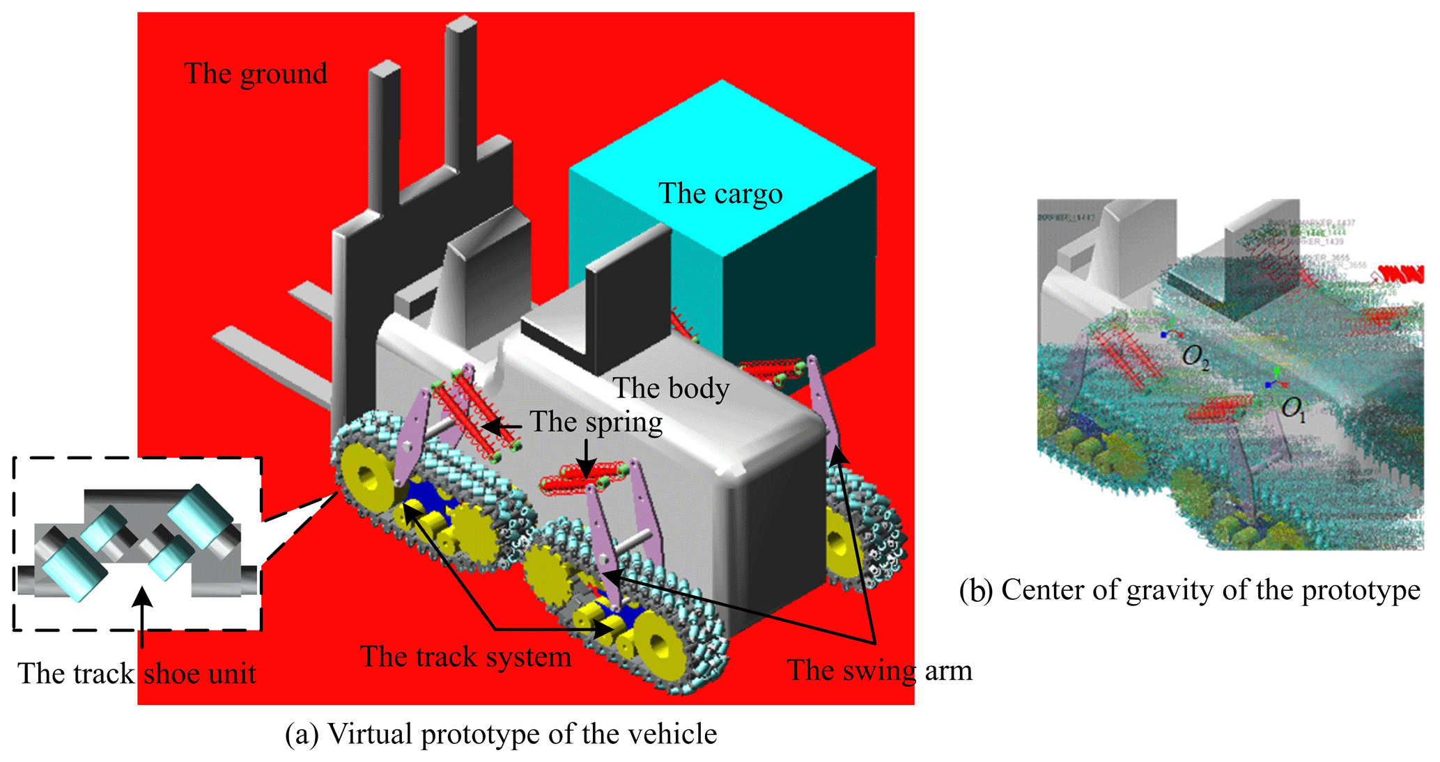
We built an accurate 3-D model of the vehicle in SolidWorks. This model contained all of the components of the real vehicle that was subsequently built, as shown in Fig. 6. We simplified the model in SolidWorks and added constraints to obtain the virtual prototype model in ADAMS, as shown in Fig. 7a (a model of cubic cargo (2 t) was added to the model). The simplification of the SolidWorks model to obtain the ADAMS model was performed through three steps.
-
Reserve. We retained key components, such as the track plates and rollers that were directly involved in the movement process and force transmission.
-
Remove. We removed connectors, such as screws and nuts, and removed parts that were not directly related to the motion simulation, such as hydraulic cylinders, joysticks, motors, and reducers.
-
Replace. We used a single part in ADAMS to replace the integrated body of each component in SolidWorks, such as the vehicle body, driving sprocket, and road wheels.
The setting of the center of gravity followed the design standard of counterweight forklifts (Tao and Wei, 2010). The centers of gravity of the virtual prototype under no-load (O1) and full-load (O2) conditions are shown in Fig. 7b.
The topological relationship between the parts of the virtual prototype in the form of a graphical topology diagram is shown in Fig. 8. The corresponding topological relationship is detailed in Table 1.

Table 1Topological relationship between parts of the virtual prototype.
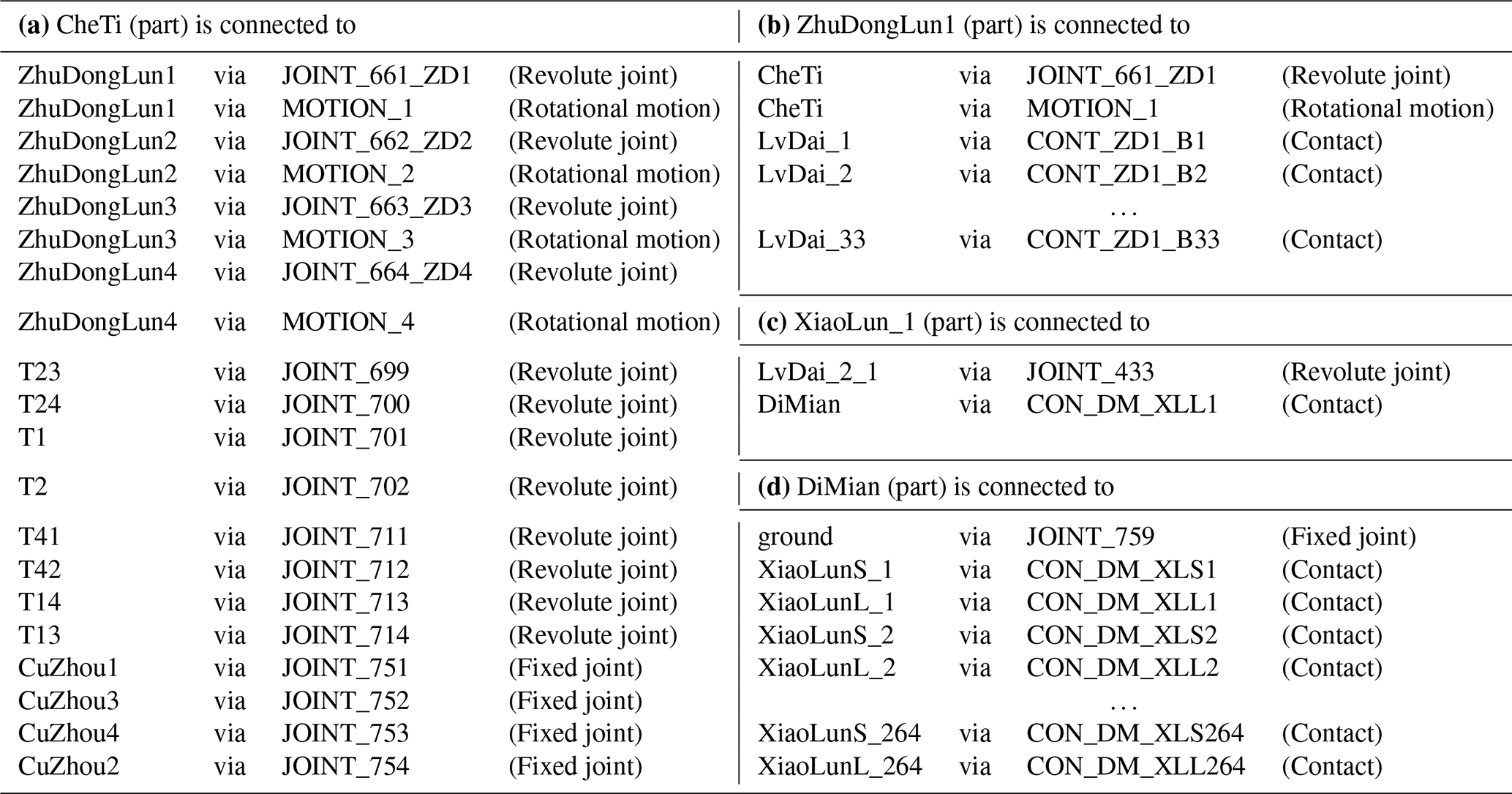
As shown in Fig. 8a and Table 1a, the body (“CheTi”) and shafts (including four parts, such as “CuZhou1”) of the swing arms were connected by fixed joints. The body and axle sleeves (including eight parts, such as “T1”) of the suspension springs were connected by revolute joints. The body and driving sprockets (including four parts, such as “ZhuDongLun1”) were connected by revolute joints, and rotational joint motions were applied to the driving sprockets. As shown in Fig. 8b and Table 1b, we added contacts between the drive wheel and track plates (including 33 parts, such as “LvDai_1”). As shown in Fig. 8c and Table 1c, the track plate (“LvDai_2_1”) and the roller (“XiaoLunL_1”) were connected by revolute joints. We added contacts between the roller (“XiaoLunL_1”) and the ground (“DiMian”). The ground was fixed to the default ground in ADAMS. The topology is shown in Fig. 8d and Table 1d from the ground perspective. The number of degrees of freedom of the virtual model was 725.
The material of the roller was hard rubber. The ground that a vehicle operates on is generally a hard, flat surface, such as cement pavement. The parameters of the contact between the roller and the ground are shown in Fig. 9 (in MKS units).
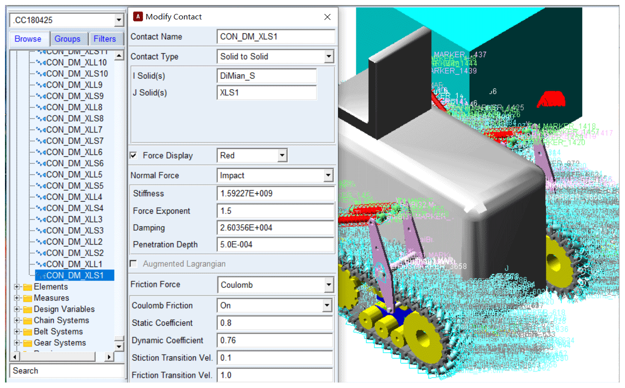
Figure 9Parameters of contact.
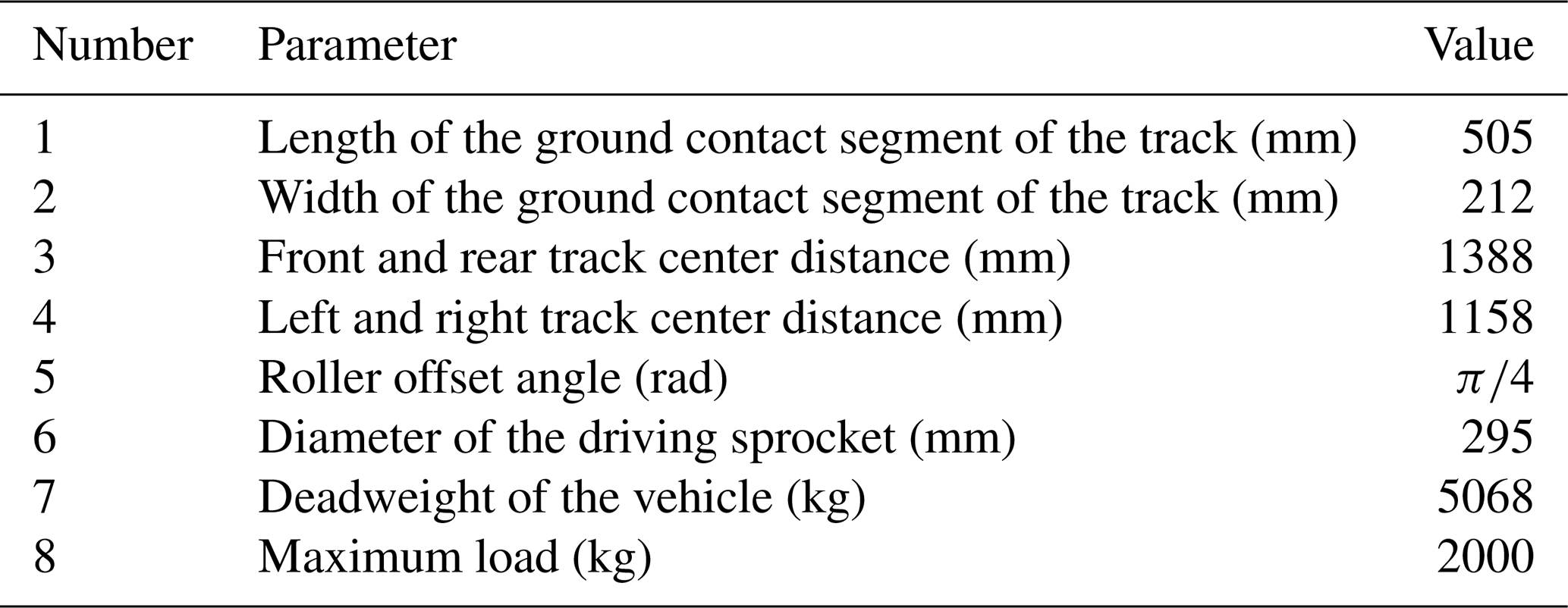
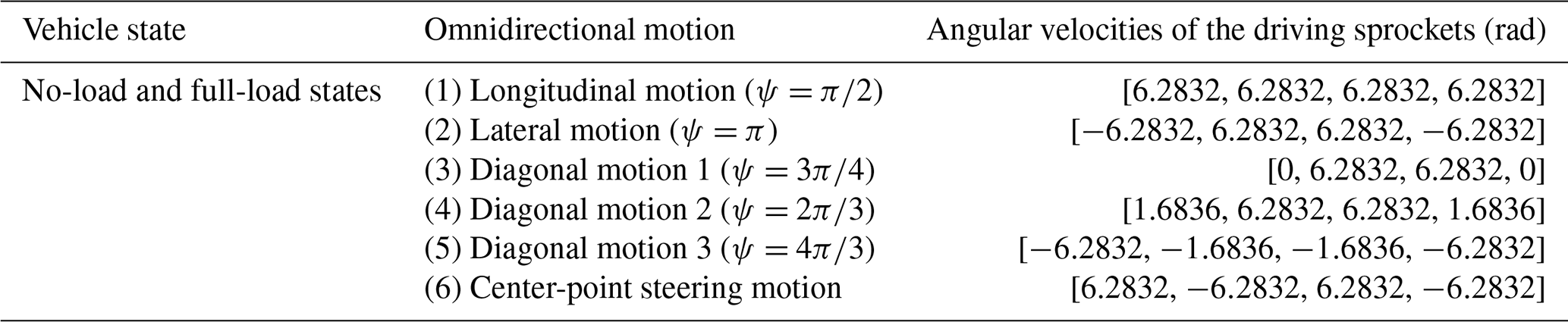
The main structural parameters of the virtual prototype are shown in Table 2. By inserting the data in Table 2 into Eq. (11), the inverse kinematical equation of the virtual prototype can be obtained. The absolute value of the maximum angular velocities of four driving sprockets was set to 2π (rad s−1), and six kinds of omnidirectional motion simulations were performed under no-load (no cargo) and full-load (2 t cargo) conditions. The omnidirectional motions of the virtual prototype and the corresponding angular velocities of the driving sprocket are shown in Table 3.
Table 3Omnidirectional motions of the prototype and corresponding angular velocities of the drive sprocket.
4.2 Dynamic simulation analysis
The simulation times of the translational motion and center-point steering motion were 8 and 13 s, respectively. The static simulation time was 0–1 s, and the simulation time of the accelerated motion was 1–3 s. In the simulation, the STEP function in the ADAMS software was used to control the angular velocity of the driving sprocket (taking longitudinal motion as an example, the expression of the STEP function was “STEP(time,1,0,3,6.2832)”). After 3 s, the motion of the virtual prototype gradually tended to be stable. Curves of the trajectory and velocity of the virtual prototype are shown in Fig. 10a–n. The left-hand side is the no-load motion image, and the right-hand side is the full-load motion image. vx represents the speed component of the x axis, vy represents the speed component of the y axis, the unit of time is s, the unit of speed is m s−1, and the unit of angular velocity is rad s−1. Numbers (1)–(6) in Fig. 10a and b correspond to motion types (1)–(6), respectively, in Table 3.
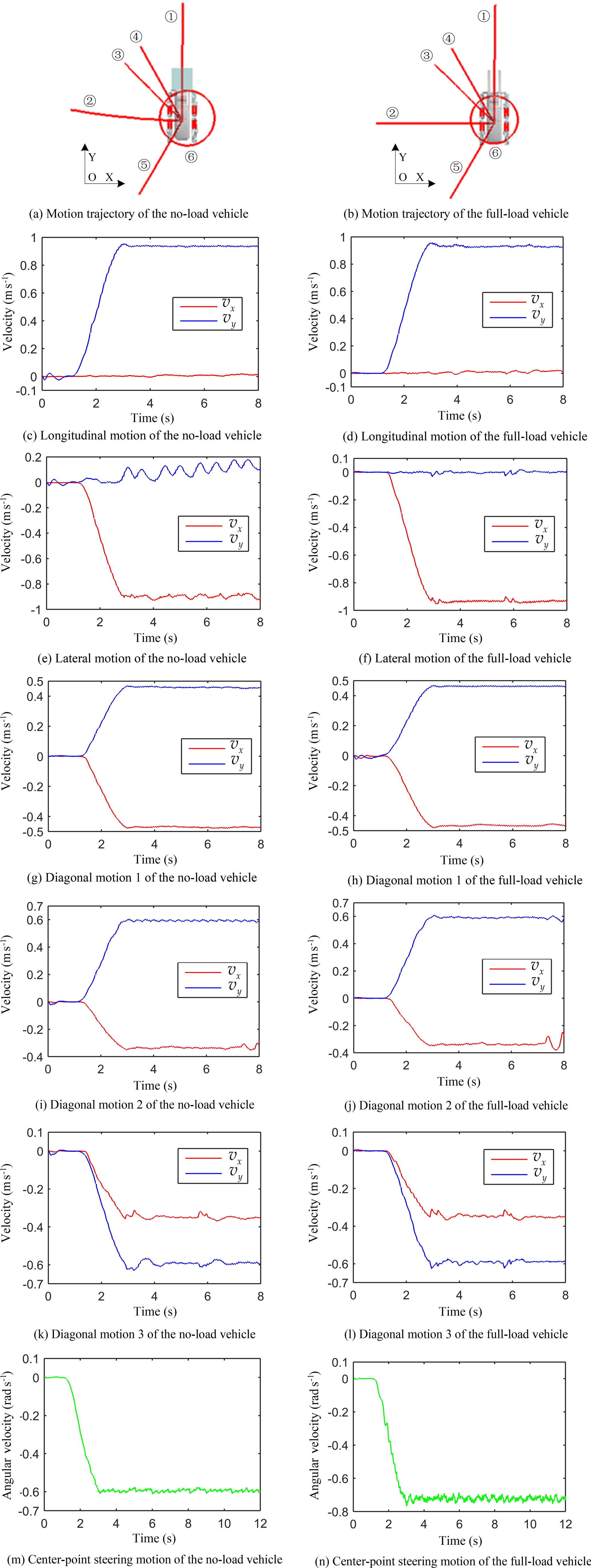
In the translational motion, the virtual prototype used the geometrical center point of the vehicle body as the trajectory point. In the center-point steering motion, the geometrical center point of the front idler in the left front track system was used as the trajectory point. According to Fig. 10a and b, the virtual prototype could basically complete six kinds of omnidirectional motions in the no-load and full-load states. The trajectory in the no-load state was more regular than the trajectory in the full-load state, and the movement was smoother. The heading angle deviation of the full-load lateral motion was 9.41∘, and the trajectory angular deviation of the full-load lateral motion was 5.5∘. VT is defined as the theoretical value of velocity (m s−1) or angular velocity (rad s−1), and VS is defined as the simulated average value of the velocity or angular velocity. Both VT and VS are absolute values. The comparison between VT and VS under the steady-state omnidirectional motion is shown in Table 4.
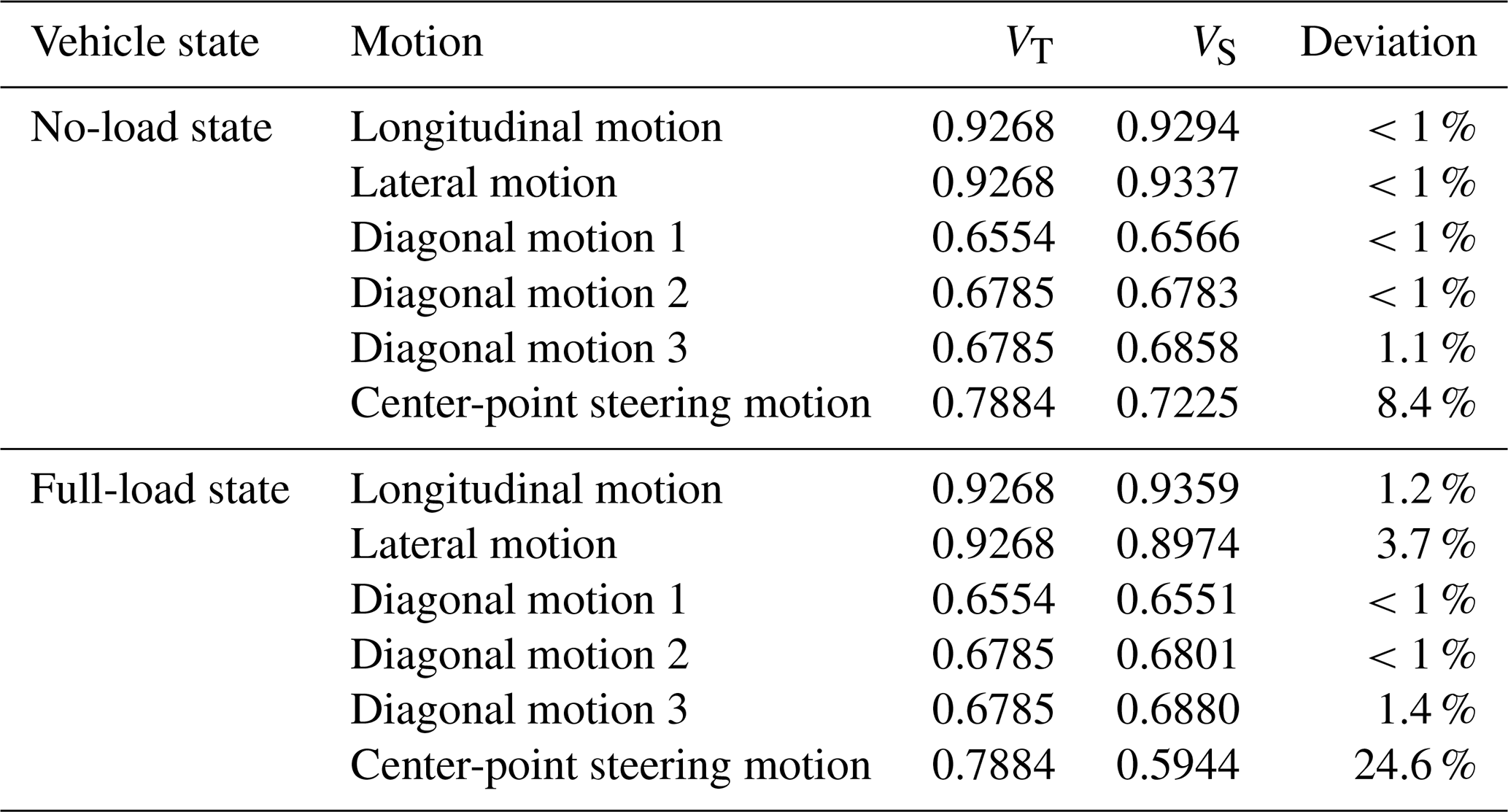
Comparing velocities of the virtual prototype in Table 4, the conclusions are as follows.
-
When the virtual prototype is in the no-load and full-load states, the longitudinal motion velocity was approximately equal to the lateral motion velocity.
-
The velocity of diagonal motion 2 was approximately equal to the velocity of diagonal motion 3.
-
The longitudinal motion velocity was about times the velocity of diagonal motion 1 and about times the velocity of diagonal motion 2 and 3.
Through the above calculations, the maximum translational velocity of the virtual prototype was consistent with the conclusion of the velocity anisotropy analysis (Eq. 4) above.
As shown in Table 4, the velocity deviation between the simulated and theoretical values was small for the translational motion of the prototype, and the deviation was large for the center-point steering motion. This was because the slippage of the track was more severe during the center-point steering motion than the translational motion, and the large mass and contour of the virtual prototype exacerbated this phenomenon. The velocity deviation value of the virtual prototype under the full load was greater than that under no load. There was an evident trajectory deviation in the full-load lateral motion and full-load center-point steering motion. This shows that the change in the center of gravity of the virtual prototype before and after loading had a great influence on the velocity and trajectory.
Based on the accurate model in SolidWorks, a real prototype of the vehicle was built. We carried out omnidirectional motion experiments on the prototype and analyzed the velocity and acceleration anisotropy of the prototype using experimental data.
5.1 Omnidirectional motion experiment
The real prototype of the medium-tracked omni-vehicle is shown in Fig. 11.
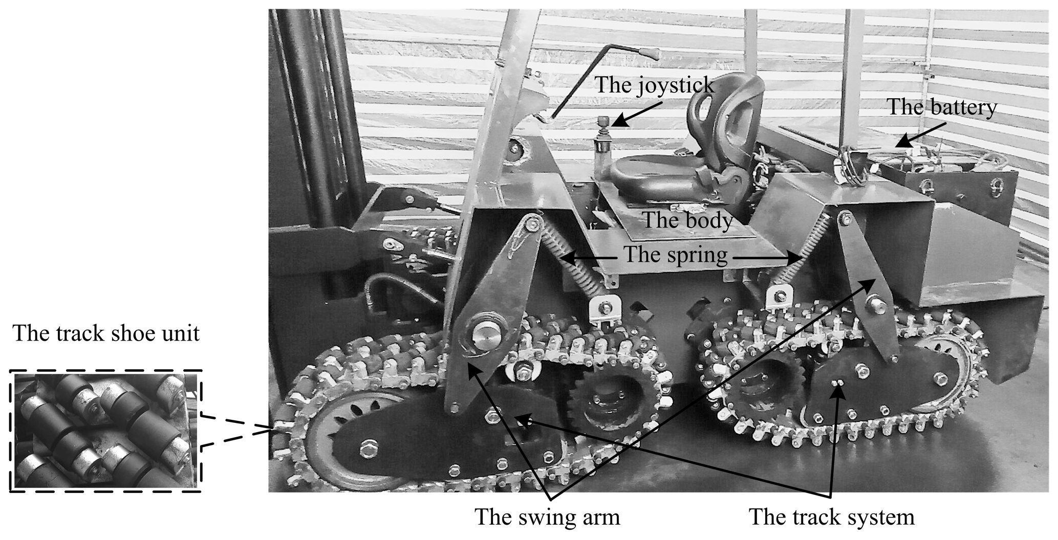

For the forklift reliability test field of an enterprise, the omnidirectional experiment of the prototype was carried out. The ground condition was dry cement. Various motion types, including longitudinal, lateral, multi-angle diagonal, center-point steering, and multi-radius steering, were carried out under no-load and full-load conditions of the prototype. Three typical omnidirectional motions (longitudinal, lateral, and center-point steering) under full-load conditions are shown in Fig. 12. Experiments showed that the prototype had the ability to perform omnidirectional motion in a plane and had high displacement accuracy. When the motor was at the maximum speed, the full-load prototype was prone to trajectory deviations and yawing phenomena during the lateral and center-point steering motions. This was consistent with the simulation conclusion shown in Fig. 10. There were no evident deviation phenomena in other directions of motion. The actual motion of the prototype was basically consistent with the results of the simulation.
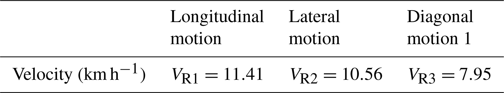
The maximum speed of the motor (which we set to 4880 rpm) was limited by the VCU (vehicle control unit) program. Using a GPS application on a smart phone, the maximum velocities of the prototype in different directions were recorded, and the average value is shown in Table 5. Based on the data in Table 5, VR1≈VR2 and . This is consistent with the analysis of the velocity anisotropy of the vehicle and simulation data.
Table 5Maximum velocity of the prototype in different directions of motion.
5.2 Driving efficiency experiment of translational motion
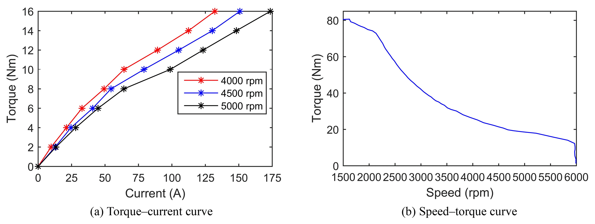
When the motor ran at the rated maximum speed, the motor output torque was proportional to the motor current. The torque–current and speed–torque curves of the motor are shown in Fig. 13. The standard for motor testing is ECE R85 (UN/ECE, 2013). The current value in Fig. 13a refers to the current value of the battery during the motor test.
The total steady-state current of the prototype was measured when it was moving in different directions. The total steady-state current was read from the BMS (battery management system) module of the battery. After several rounds of experiments on the dry cement ground, the average value of the total current of three typical translational motions (longitudinal, lateral, and 135∘ diagonal) was recorded under no-load and full-load conditions of the prototype, as shown in Table 6. The battery voltage was always between 81 and 82 V in the whole moving process, and the fluctuation range was small.
Table 6Average value of the total current of three typical translational omnidirectional motions.

As shown in Table 6, the total current in the lateral motion was about twice the total current in the longitudinal motion (the error of the no-load state was 4.0 %, and the error of the full-load state was 8.6 %). Combined with the analysis of Sect. 2.2, this shows that the angular velocity of the roller was basically zero when the prototype traveled straight. In Table 6, the total current during the lateral motion of the prototype was about times during the 135∘ diagonal motion (the error of the no-load state was 8.3 %, and the error of full-load state was 7.8 %). The above analysis agrees with the conclusion of maximum translational velocity and acceleration anisotropy given by Eq. (10), which verifies the correctness of the theory.
In summary, the conclusions are as follows.
-
Compared with conventional vehicles, the tracked omni-vehicle exhibited unique motion anisotropy in terms of the velocity and acceleration. Because the position of the omnidirectional mobile mechanism relative to the vehicle (layout) was determined, the motion anisotropy depended on the offset angle of the roller.
-
The torque ratio formula of the translational motion was proposed, and the correctness of the ratio formula was verified by the results of the experiment.
-
The analysis of the simulation results showed that the deviation of the trajectory and velocity of the prototype under the no-load state was much smaller than that under the full-load state. The consistency between the simulated and theoretical values of the translational velocity was high. There was a large deviation between the simulated and theoretical values of the angular velocity of the center-point steering motion.
The prototype exhibited different motion characteristics under no-load and full-load conditions due to changes in the center of gravity. In a future study, the corresponding control strategy and control algorithm will be studied to reduce the deviation and obtain the desired trajectory and velocity. Another important future research direction is to establish a precise mathematical model of the steering kinematics and dynamics of the vehicle that accounts for slip. The simulation speed, trajectory data, and real vehicle power data of the prototype can provide data verification for the mathematical model presented above.
In summary, in this study, it was shown that building a large, heavy-duty medium-tracked omni-vehicle is feasible. The prototype presented in this paper can provide a reference for the design of other large, heavy-duty omnidirectional vehicles. By adding various sensors and fixtures and the corresponding control algorithms, the medium-tracked omni-vehicle can be used as a factory AGV, a port and dock freight platform, an urban counter-terrorism combat platform, or an accompanying combat support platform. This vehicle will play a significant role in transportation, logistics, military applications, and other fields.
All the data used in this paper can be obtained from the corresponding author on request.
Conceptualization was by YF, YZ, NL, and YS. Data curation was done by YF, YZ, NL, and YS. Formal analysis was made by YF. Investigations were carried out by YF, NL, and YS. The methodology is by YF and YZ. Project administration was performed by YZ. Resources came from YZ. Software came from YF. Supervision was by YZ. Visualization was by YF. YF wrote the original draft. Writing, review, and editing were done by YZ, NL, and YS.
The authors declare that they have no conflict of interest.
We thank LetPub (https://www.letpub.com, last access: 3 April 2020) for its linguistic assistance during the preparation of the manuscript.
This research has been supported by the Basic Research Programs of the State Administration of Science, Technology and Industry for National Defense, PRC (grant no. 2015ZB15).
This paper was edited by Daniel Condurache and reviewed by two anonymous referees.
Cao, A.: Omni-directional all-terrain six-wheeled tracked vehicle, Patent: National Intellectual Property Administration, PRC, CN106240663B, Beijing, China, 2018.
Chen, P., Mitsutake, S., Isoda, T., and Shi, T.: Omni-directional robot and adaptive control method for off-road running, IEEE T. Robotic. Autom., 18, 251–256, https://doi.org/10.1109/TRA.2002.999654, 2002.
Clavien, L., Lauria, M., and Michaud, F.: Instantaneous centre of rotation based motion control for omnidirectional mobile robots with sidewards off-centred wheels, Robot. Auton. Syst., 106, 58–68, https://doi.org/10.1016/j.robot.2018.03.014, 2018.
Isoda, T., Peng, C., Toyota, T., and Hirano, T.: Omni-directional mobile robot for autonomic offroad running, Proceedings 6th IEEE International Workshop on Robot and Human Communication, RO-MAN'97, 64–69, IEEE, Sendai, Japan, 1997.
Karavaev, Y. L. and Kilin, A. A.: Nonholonomic dynamics and control of a spherical robot with an internal omniwheel platform: Theory and experiments, P. Steklov Inst. Math., 295, 158–167, https://doi.org/10.1134/s0081543816080095, 2017.
Madhushani, T. W. U., Maithripala, D. H. S., Wijayakulasooriya, J. V., and Berg, J. M.: Semi-globally exponential trajectory tracking for a class of spherical robots, Automatica, 85, 327–338, https://doi.org/10.1016/j.automatica.2017.07.060, 2017.
Mortensen Ernits, R., Hoppe, N., Kuznetsov, I., Uriarte, C., and Freitag, M.: A New Omnidirectional Track Drive System for Off-Road Vehicles, 2017 XXII International Conference on “Material Handling, Constructions and Logistics”, FME Belgrade, Belgrade, Serbia, 2017.
Pan, J., Shi, Z., and Wang, T.: Variable-model SMA-driven spherical robot, Science China Technological Sciences, 62, 1–11, https://doi.org/10.1007/s11431-018-9408-3, 2019.
Park, Y. K., Lee, P., Choi, J. K., and Byun, K. S.: Analysis of factors related to vertical vibration of continuous alternate wheels for omnidirectional mobile robots, Intel. Serv. Robot., 9, 207–216, https://doi.org/10.1007/s11370-016-0196-3, 2016.
Peng, T., Qian, J., Zi, B., Liu, J., and Wang, X.: Mechanical Design and Control System of an Omni-directional Mobile Robot for Material Conveying, Proc. CIRP, 56, 412–415, https://doi.org/10.1016/j.procir.2016.10.068, 2016.
Roh, S.-G., Taguchi, Y., Nishida, Y., Yamaguchi, R., and Hirose, S.: Development of the portable ground motion simulator of an earthquake, 2013 IEEE/RSJ International Conference on Intelligent Robots and Systems (IROS), IEEE, Tokyo, Japan, 2013.
Sheikhlar, A., Fakharian, A., Beik-Mohammadi, H., and Adhami-Mirhosseini, A.: Design and Implementation of Self-Adaptive PD Controller Based on Fuzzy Logic Algorithm for Omni-Directional Fast Robots in Presence of Model Uncertainties, International Journal of Uncertainty, Fuzziness and Knowledge-Based Systems, 24, 761–780, https://doi.org/10.1142/s0218488516500343, 2016.
Singh, A., Sachdeva, E., Sarkar, A., and Krishna, K. M.: COCrIP: Compliant OmniCrawler In-pipeline Robot, 2017 IEEE/RSJ International Conference on Intelligent Robots and Systems (IROS), 5587–5593, IEEE, Vancouver, BC, Canada, 2017.
Tadakuma, K., Hirose, S., and Tadakuma, R.: Development of VmaxCarrier2: Omni-directional Mobile Robot with Function of Step-climbing, IEEE International Conference on Robotics and Automation, Proceedings, ICRA'04, IEEE, New Orleans, LA, USA, 2004.
Tadakuma, K., Ming, A., Shimojo, M., Tadakuma, R., Nagatani, K., Yoshida, K., and Iagnemma, K.: Basic running test of the cylindrical tracked vehicle with sideways mobility, 2009 IEEE/RSJ International Conference on Intelligent Robots and Systems, IEEE, St. Louis, MO, USA, 2009a.
Tadakuma, K., Tadakuma, R., Nagatani, K., Yoshida, K., Aigo, M., and Shimojo, M.: Throwable tetrahedral robot with transformation capability, 2009 IEEE/RSJ International Conference on Intelligent Robots and Systems, 10–15 October 2009, IEEE, St. Louis, MO, USA, 2009b.
Tadakuma, K., Tadakuma, R., Higashimori, M., and Kaneko, M.: Robotic finger mechanism equipped omnidirectional driving roller with two active rotational axes, 2012 IEEE Int. Con. Robot., 3523–3524, 2012.
Tadakuma, K., Takane, E., Fujita, M., Nomura, A., Komatsu, H., Konyo, M., and Tadokoro, S.: Planar Omnidirectional Crawler Mobile Mechanism – Development of Actual Mechanical Prototype and Basic Experiments, IEEE Robotics and Automation Letters, 3, 395–402, https://doi.org/10.1109/LRA.2017.2739101, 2017.
Tao, Y. and Wei, L.: Structure and Design of Forklifts, China Machine Press, Beijing, 197 pp., 2010.
Tong, Z.: A motion study of the omnidirectional mobile robot, Master Degree, Shenyang Aerospace University, ShenYang, LiaoNing, China, 2017.
UN/ECE (Economic Commission for Europe of the United Nations): Regulation No 85 of the Economic Commission for Europe of the United Nations (UN/ECE) – Uniform provisions concerning the approval of internal combustion engines or electric drive trains intended for the propulsion of motor vehicles of categories M and N with regard to the measurement of net power and the maximum 30 minutes power of electric drive trains, OJEU (Official Journal of the European Union), Brussels, Belgium, 2013.
Wang, X.: Theory and Application of Mecanum Wheel Based Omni-directional Mobile, Southeast University Press, Jiang Su, 2018.
West, M. and Asada, H.: Design of Ball Wheel Mechanisms for Omnidirectional Vehicles With Full Mobility and Invariant Kinematics, J. Mech. Design, 119, 153, https://doi.org/10.1115/1.2826230, 1997.
Yang, Y., Yang, G., Tian, Y., Zheng, T., Li, L., and Wang, Z.: A robust and accurate SLAM algorithm for omni-directional mobile robots based on a novel 2.5D lidar device, 13th IEEE Conference on Industrial Electronics and Applications (ICIEA), IEEE, Wuhan, China, 17879075, 2018.
Ye, C., Tong, Z., Yu, S., and Jiang, C.: Kinematic Analysis of an Omnidirectional Mobile Assembly Robot, Robot, 38, 550–556, https://doi.org/10.13973/j.cnki.robot.2016.0550, 2016.
Zhang, G.: Design and control of spherical Mecanum weel trolley, Master Degree, Huazhong University of Science and Technology, WuHan, HuBei, China, 2018.
Zhang, Y. and Fang, Y.: Tracked vehicle and running mechanism with swing arm suspension, Patent: National Intellectual Property Administration, PRC, CN110329375A, Beijing, China, 2019a.
Zhang, Y. and Fang, Y.: Multi-support and multi-roller track components and tracks, Patent: National Intellectual Property Administration, PRC, CN110395324A, Beijing, China, 2019b.
Zhang, Y. and Huang, T.: Research on a tracked omnidirectional and cross-country vehicle, Mech. Mach. Theory, 87, 18–44, https://doi.org/10.1016/j.mechmachtheory.2014.12.016, 2015.
Zhang, Y., Yang, H., Huang, T., Zhang, S., and Fang, Y.: Analysis about Motion of Centripetal Tracked Omnidirectional Mobile Platforms, Acta Armamentarii, 38, 2309–2320, 2017.
Zhao, D. and Yi, J.: Introduction to omni-directional wheeled mobile robot, Science Press, Beijing, 2010.
- Abstract
- Introduction
- Track structure and track layout
- Motion analysis of medium-tracked omni-vehicle
- Simulation analysis of the medium-tracked omni-vehicle
- Experiments of a medium-tracked omni-vehicle
- Conclusions and future lines
- Data availability
- Author contributions
- Competing interests
- Acknowledgements
- Financial support
- Review statement
- References