the Creative Commons Attribution 4.0 License.
the Creative Commons Attribution 4.0 License.
 | 07 Apr 2020
Optimum design of the double roll rotary forging machine frame
Lei Shi
Chun Dong Zhu
Xin Liu
Yi Zhang
The equipment to realize the rotary forging technology is called the rotary forging machine. Compared with the common forging equipment, machine frame will bear a large torsion force in the working process, and the load in the forming process will eventually act on the rotary forging machine frame, and cause it to deform, thus affecting the rolling situation of the workpiece. Therefore, good frame performance is the premise to achieve stable rotary forging. The good performance of the frame is closely related to the structural design and structural optimization. However, at present, there are few researches on the overall optimization design of the rotary forging machine, and the lightweight technology has become the current trend. In the early manufacturing of low tonnage rotary forging machine, the lightweight design is not paid enough attention to, even if it meets the use performance, but the machine is bulky, which seriously reduces the utilization rate of materials and increases the manufacturing costs. In this paper, based on the existing rotary forging machine, the topological optimization of the main body of the rotary forging machine is carried out, and then the sensitivity analysis of the thickness of each component of the machine frame to the performance of the frame is studied, which provides the basis for the follow-up size optimization. Finally, the experimental verification is carried out, and it is found that the work pieces of the rotary forging are relatively good, which shows that the optimization scheme is reasonable and can be reduced on the premise of satisfying the performance weight, saving manufacturing cost.
- Article
(2121 KB) - Full-text XML
- BibTeX
- EndNote


Rotary forging is a continuous local pressure plastic forming technology (Zhang, 1984; Zhu et al., 2011, 2015; Liu et al., 2019). Compared with the common integral forming process, the advantages of rotary forging are labor-saving, small vibration and impact, good deformation quality, high precision, easy to realize mechanization and automation in deformation process (Deng et al., 2011; Han et al., 2014; Hua and Han, 2009a). Because the forming pressure required by rotary forging is only 1∕5–1∕20 of that of ordinary press, it can be used to form products requiring large tonnage equipment, and it is also relatively more suitable for forming parts with thin parts, large diameter to thickness ratio and complex end face shape (Hua and Han, 2009b). In the early stage of rotary forging, a lot of research has been done in the fields of force and energy parameters, influencing factors, finite element analysis, etc. (Oh and Choi, 1997a, b; Wang and Zhao, 2002). Because of the appearance of cold rotary forging technology, many scholars have carried out in-depth research on it, making it widely used in various fields (Samoyk, 2013; Han et al., 2016, 2017). For the research of rotary forging machine body, some modeling and analysis methods are summarized in the aspects of design method, dynamic and static characteristics, local optimization and finite element analysis (Nam et al., 2014; Kim et al., 2006; Citipitioglu et al., 2002). However, the research on the double roll rotary forging machine body is scarce, especially in the overall optimization and lightweight. Many scholars have done a lot of research on structural optimization and lightweight, aiming to optimize the structure, reduce the weight and improve the material utilization rate (Jiao et al., 2012; Duan and Wu, 2011; Strano et al., 2013), which provides a reference for the optimization of the rotary forging machine body.Therefore, the purpose of this paper is to study the structure optimization and size optimization of the double roll rotary forging machine frame, to study the influence law of each component of the frame on its performance, and to explore a reasonable structure size combination that meets the requirements of stiffness and strength performance and has small mass by using optimization analysis method, so as to achieve the purpose of frame optimization and lightweight.
The double roll rotary forging process uses a pair of symmetrical rollers to rotate around their own central axis while rotating around the symmetrical axis, so as to realize the axial rolling cumulative deformation of the blank. The schematic diagram is shown in Fig. 1. The lower die moves upward under the action of the hydraulic cylinder, and under the action of the friction between the roller and the workpiece, the rotary head and the workpiece will rotate relatively. Because of the feed movement of the lower die, the roll extrudes the workpiece, which forms the local continuous accumulated deformation of the workpiece and finally forms the workpiece.

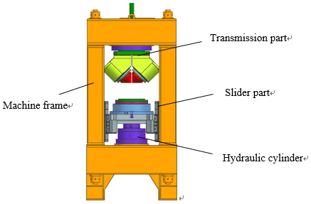
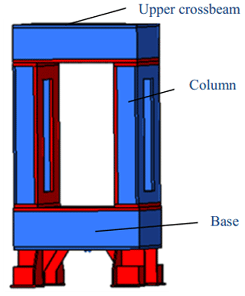
It can be seen from Fig. 2 that the main structure of the double roll rotary forging machine is mainly composed of the motor transmission part, the frame part, the transmission part, the mold part, the slider part and the hydraulic cylinder part. In fact, in addition to the main structure of the double roll rotary forging machine, it should also include some supporting equipment such as high-pressure pump station, power supply cabinet and operation console.
3.1 Parameters of double roll rotary forging machine
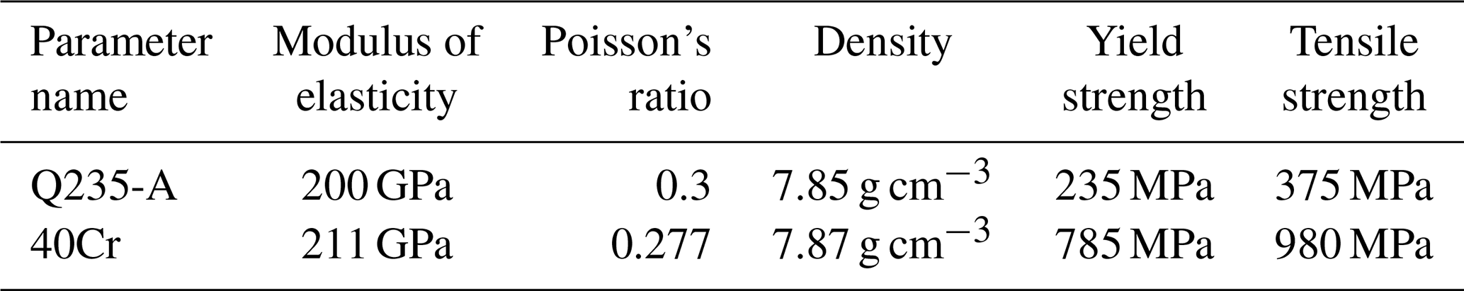
The model of the rotary forging machine studied in this paper is D52-500, the maximum forging force is 500 t, the fuselage adopts a large number of welding structures, and there are many steel plates, so that the machine is heavy and the material utilization rate is low. The material used for the column is 40Cr, and the other material is Q235-A. The material parameters are shown in Table 1.
3.2 Finite analysis of double roll rotary forging machine
3.2.1 Stress analysis of machine frame
Before the optimization analysis of the rotary forging machine frame, the finite element analysis of the rotary forging machine body is needed in order to provide the basis for the subsequent structural optimization. Because the load and boundary conditions are needed in the finite analysis, the mechanical analysis of the rotary forging machine is carried out first. There is a pretightening force in the rotary forging machine, which makes the whole frame form a certain amount of preload, so that the components of the machine body keep close connection. During the forming process, the workpiece is not only under the pressure of the vertical direction, but also under the tangential forming force along with the feeding. The force is driven by the motor to rotate the transmission parts, and acts on the workpiece by the cone roller. Because of the symmetrical structure of the cone roller, a pair of force couple is generated. Similarly, the force couple moment and its reaction force couple will also act on the upper and lower workbenches respectively with the transmission, and its value is equal but the direction is opposite. The mechanical model of the double roll rotary forging machine is shown in Fig. 3, where Py is the pretightening force applied to the four corners of the frame, P0 is the working load during the rotary forging process, and M is the couple moment generated during rolling. The calculation formula of pretightening force Py is:
where Z is the pretightening coefficient, generally 1.5 Pg: Nominal force, nominal force 5000 kN; Fz is the cross sectional area of column, 400×400 mm Fl: Cross sectional area of pull rod, diameter 140 mm; Ez is the elastic modulus of column, 200 GPa El: elastic modulus of pull rod, 210 GPa and LZ is the working length of column, 2148 mm Ll: working length of pull rod, 3548 mm.

3.2.2 Establishment of finite element model of rotary forging machine frame
(1) Model simplification
When building a model in the hypemesh software, we should pay attention to the following points:
-
The overall dimension of the frame structure shall be accurate and be consistent with the shape of its own structure.
-
In the hypomesh software, the structural features that have no obvious influence on the analysis results, such as chamfer ing and rounding, can be changed to plane or omitted, and the small hole structures such as threaded holes and pin holes should be removed.
-
It is assumed that each plate of the rotary forging frame is made of the same elastomer material, and the mass distribution of each plate is uniform.
-
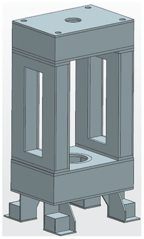
The structure of each component of the frame is welded by steel plate. The weld structure shall be simplified, and there is no defect at the welding position, which has no effect on the force transmission between the plates. The final simplified model of the frame is shown in Fig. 4.
(2) Add material properties
In the body of the double roll rotary forging machine, the crossbeam, column and base are all welded by steel plates of different thickness, the material used is Q235-A, the material used for the four pretightening pull rods is 40Cr, and the material parameters are given in Table 1.
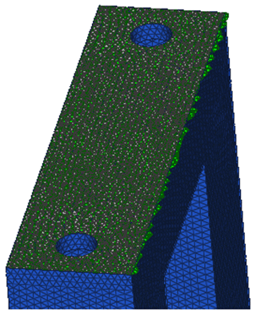
(3) Mesh generation
By using the method of volunm tetra, the size of the unit is to set 25 mm, and the final model of the whole machine has 847 415 units and 249 061 panel points.
(4) Application of boundary constraints
The upper crossbeam, column and base of the frame are all welded by each plate. In this case, the components are regarded as a whole without considering the connection of the weld, so the connection between the plates is directly in the way of joint. Because of the pretension of the pull rod, the whole machine has been in the state of compression. Assuming that there is no gap between the upper beam and the column, the three parts can also be regarded as a whole. The surface contact between them can be connected by face-to-face contact or joint mode. Here, the face-to-face contact mode is used. As shown in Fig. 5, the contact friction coefficient is set to 0.5. The frame of the double roll rotary forging machine is fixed on the ground and fixed constraints are added.
(5) Applied load
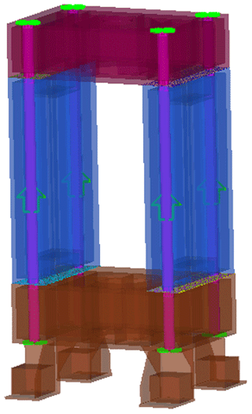
The pretightening force of the frame is mainly applied by four pretightening rods distributed at the four corners of the frame. Here, the pretightening rods are created by using the method of creating pretightening bolts in the software. In HyperMesh, the pretension manager function can be directly used to set the pretension. The pretension coefficient of the pull rod can be taken as 1.5. According to Eq. (1) obtained above, it can be calculated that the designed double roll rotary forging frame needs to load a total of 4368 KN of preload. Then the corresponding four pull rods, each of which needs to load 1092 KN of preload,as shown in Fig. 6.
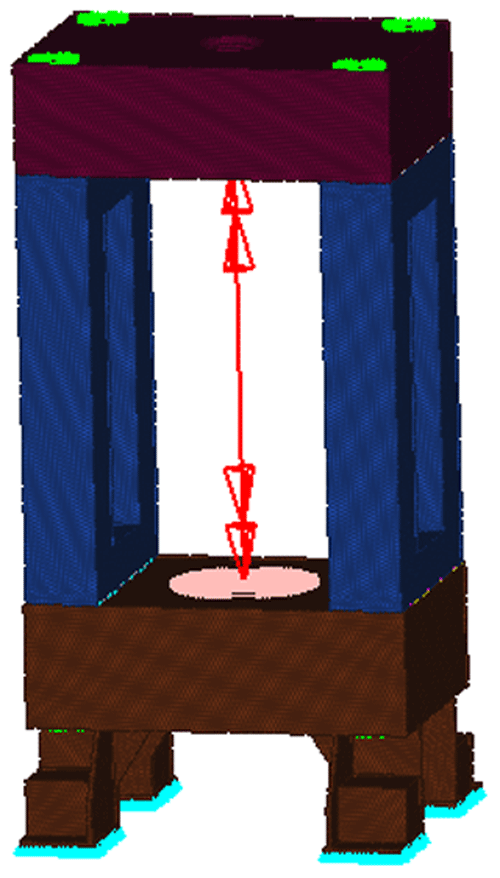
Application of nominal force: Application of nominal force: after the application of pre tightening force, nominal force shall also be applied. Since this paper studies the optimization of machine frame, the working condition of the machine under full load should be analyzed, that is, the nominal force is 5000 KN, and the torque is 2 0167 000. After the nominal force is applied to the frame model, as shown in Fig. 7.
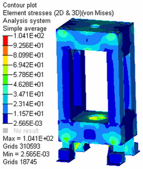
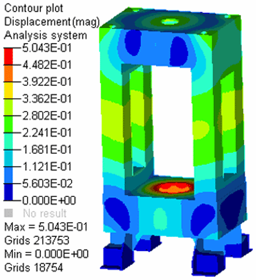
After completing the machine frame load and boundary conditions, submit the task analysis. The stress diagram and strain diagram of the frame are obtained, as shown in Figs. 8 and 9. It can be seen from Fig. 8, the effective stress diagram of the machine body that the maximum stress reaches 104.1 MPa, which is less than the allowable stress 156 MPa (the minimum safety factor of the strength of the rotary forging machine frame is 1.5, while the material yield strength is 235 MPa, ). As shown in Fig. 9, the maximum effective strain of the frame is 0.5043 mm, which is at the support of the hydraulic cylinder of the working table of the lower base. In view of the small stress on the frame, there is some space for further optimization, so the next step is to optimize the structure of the rotary forging machine frame.
3.3 Structure optimization design of rotary forging machine frame
In this paper, the overall structure of the double roll rotary forging machine frame will be optimized by using the Optistruct module of HyperMesh software. The optimization design of the structure runs through the whole design process. In the early stage of design, constraints can be set according to the performance requirements of the structure to optimize, so as to meet the expected design requirements. In the process of optimization design analysis, the first step is to determine a reasonable plan. The design model is as follows:
At this time, the structural optimization problem can be understood as: solving the set n structural parameter variables, when the given constraints and conditions are met, the objective function can be optimized. When these three main factors are set in the optimization of Optistruct, the design variables can be size parameters, material properties, etc., the constraints can be set as the structure frequency range, maximum stress range, allowable deformation range, etc. For the objective function, the minimum mass, minimum volume, maximum stiffness, maximum stress, etc. are usually selected.
In the common topology optimization methods, the variable density method is simpler than the uniform method. The variable density method assumes that the density of the material can change between [0, 1]. When the structural characteristics are related to the density of the material, the performance change can be adjusted by increasing or decreasing the material. If the unit density is 0, it should be deleted, and if it is 1, it should be retained. Topology optimization is often used in the problems of maximum stiffness, minimum mass or maximum first-order frequency. When setting topology optimization in Optistruct, it can be divided into the following main steps, as shown in Fig. 11. The specific process is to create Topology optimization task: Responses; Deconstrains; Objective.
In the topology optimization of 5000 kN double roll rotary forging machine frame, the simplified frame model which has been used in the previous finite element analysis can continue to be used. However, since the topology optimization process is carried out by the variable density method, during the optimization process, according to different constraint conditions and target settings, the optimized frame will form a void on the ribs of different component structures According to the actual working situation of the frame, some structures must be reserved and no structural pruning is needed. The topology optimization model of rotary forging machine is shown in Fig. 10. One part is the blue area for optimization design, and the other part is the red non design structure. In order to ensure the strength of the frame, reduce the weight of the whole machine and optimize the rigidity, the topology optimization design of the rotary forging frame is carried out, and the model is constructed according to the following three aspects:
-
Objective function: the objective function is to minimize the strain energy of the frame structure when the double roll rotary forging machine is in full load operation, that is, the frame is affected by the maximum rolling force and torque at the same time.
-
State variable: the maximum stress on the whole frame of double roll rotary forging machine shall not be greater than the allowable stress of the material, that is, the maximum stress ≤ 158 MPa. In order to reduce the mass of the frame, the volume fraction response Volumefrac is used instead of the mass constraint, that is, the volume of the optimized design area accounts for the percentage of the overall original volume of the frame. After a series of parameter tests, through comparison, it is found that it is appropriate to set the volume fraction response ≤ 0.6.
-
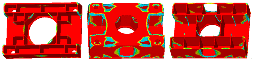
Design variable: change the unit density of each component of the frame to optimize the overall structural stiffness. After analyzing and calculating the topology optimization model of the designed rotary forging frame, Fig. 12 shows the convergence process graph of the strain energy of the machine frame. The overall model of the optimized frame (observe when the unit density is ≥0.2) is shown in Fig. 13. Through the analysis of the main optimization area of each component of the frame, the unit density diagram of its local area is obtained, as shown in Fig. 14.

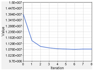
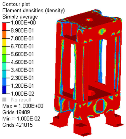
It can be seen from Fig. 12 that the strain energy of the frame decreases with the increase of the number of iterations. After four iterations, the value of strain energy basically meets the set requirements, tends to be stable and does not change. After eight iterations, the topology optimization of the whole process is completed. In Fig. 13, the area shown in red is the part with the optimized density value of 1, that is, the position that must be reserved. As the color gradually changes to blue, the density will gradually approach 0, and the importance of regional material reservation will decrease accordingly.
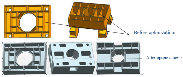
By observing Figs. 13 and 14, the installation or fixing position should not be removed. Some minor local structures can be hollowed out, but the integrity of the structure connection should be ensured. From the overall observation of the column structure, it is found that the outer plate of the column is basically reserved. As for the base of the rotary forging machine frame, it is closer to the fixed ground, and the structural performance is relatively stable. Therefore, when the topology is optimized, the influence of the structure on the rigidity of the rotary forging frame is relatively small, and the optimized model can remove more materials. Figure 15 shows the final determined model of rotary forging frame after topology optimization, and Fig. 16 shows the structure of local model after frame optimization.
Because after topology optimization analysis, some adjustments have been made to the parts and details of the model, so it is necessary to analyze the performance after the structural changes. It is found that the mass decreased by 5.32 % and the maximum stress changed little, which is in accordance with the preliminary optimization design.
3.4 Sensitivity analysis of frame structure
In the optimization design of structural model, there are often too many design parameters, it is difficult to judge impact of various variables on the performance of the structure. Therefore, before the multi variable and multi-objective optimization design of the structure, the sensitivity analysis should be carried out first to clarify the influence factors of each design variable on the structure characteristics to be optimized, and then the optimal scheme should be determined by adjusting the appropriate variable factors.
3.4.1 Variable design of sensitivity analysis of double roll rotary forging frame
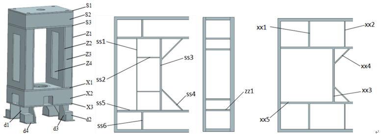
The main components of the double roll rotary forging machine frame are all welded by plates, and the performance of each plate to the frame is related and affected each other. Therefore, through the sensitivity analysis of the static and dynamic characteristics of the plate thickness of each component of the frame, the plate thickness that has a great impact on the performance of the frame can be extracted, which provides an accurate reference for further size optimization.After simplification, the model of double roll rotary forging machine can be regarded as the combination of 26 kinds of structural plates, that is to say, the thickness of 26 different plates should be defined as design variables in the process of optimization analysis. The position of each plate is shown in Fig. 17.
3.4.2 Sensitivity analysis of component plate thickness to frame performance
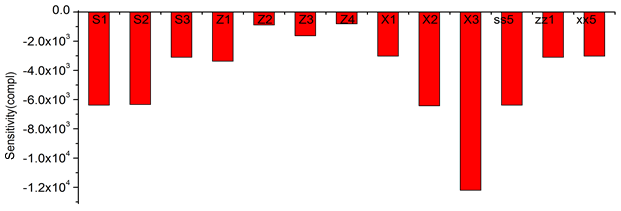
(1) Sensitivity analysis of quality
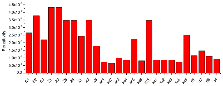
When the overall mass of the frame of the double roll rotary forging machine is taken as the goal and the thickness of each component plate of the frame is taken as the variable, the sensitivity of each component plate thickness to the overall quality can be obtained, as shown in Fig. 18. It can be seen from the figure that the thickness of S1, S2, S3, Z1, Z2, Z3, Z4, x1, X2, X3, SS5, zz1 and XX5, that is, the thickness of the upper crossbeam, the outer plate of the column and the base, as well as the inner diaphragm of them, has a great impact on the mass of the frame. Because these plates are the basic frame of the rotary forging frame, they account for a large proportion of the structural mass, while others plates mainly play the role of support and force transmission, so the impact on the overall mass of the frame is smaller compared with these main plates. Therefore, for the purpose of reducing the weight of the frame structure and reducing the variables, the later analysis mainly considers these plates with large mass.
(2) Sensitivity analysis of stiffness
In HyperMesh, flexibility is mainly used to analyze the stiffness sensitivity of the frame. The larger the flexibility value is, the more likely the frame is to deform, that is, the worse the stiffness. Taking the flexibility as the objective and the thickness of each plate as the variable, the sensitivity histogram of the thickness of each main component plate of the rotary forging frame to the flexibility is shown Fig. 19. It can be seen from the figure that S1, S2, X2, X3 and SS5 have relatively high influence factors, and S3, Z1, x1, zz1 and XX5 have the second largest contribution, while Z2, Z3 and Z4 have relatively low sensitivity. It can be seen that the thickness of the composite plate of the upper crossbeam and the base has a greater impact on the rigidity of the frame, because these two parts are the main load-bearing parts of the frame, which are more prone to deformation, so when optimizing, we can consider increasing the thickness of these plates, so as to reduce the flexibility of the frame and improve the rigidity.
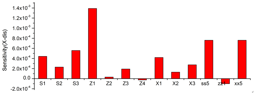
(3) Sensitivity analysis of horizontal deformation displacement
The double cone rollers of the double roll rotary forging machine are arranged symmetrically, and the frame will not be affected by bias load generally, but it will produce a certain deformation displacement in horizontal direction in the process of rotary forging. The horizontal (X) deformation displacement of the column can be used to measure its horizontal stiffness. Therefore, taking the X-direction deformation displacement of the side of the column as the target, we can get the sensitivity histogram of the main component plate thickness of the column to its horizontal deformation, as shown in Fig. 20. According to Fig. 20, the sensitivity of Z1, that is, the thickness of the outer plate of the column, is the highest, because the column is the main part of the horizontal displacement of the machine frame, so it is necessary to increase Z1 appropriately in optimization to improve the horizontal rigidity performance of the frame. For S1, S3, X1, ss5 and xx5, they also have some influence on the horizontal deformation of the frame, but they are weaker than Z1.
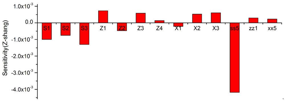
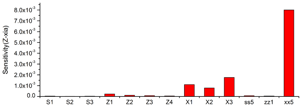
(4) Sensitivity analysis of vertical deformation displacement
The vertical rigidity of the frame is mainly measured by the deformation displacement in the vertical (Z) direction of the upper and lower workbenches, so the Z-direction deformation displacement of the upper and lower workbenches are taken as the targets here, and the sensitivity histogram of the thickness of the main plate of the frame to its vertical deformation is obtained, as shown in Figs. 21 and 22. Combined with the two figures, it can be seen that the Z-direction deformation displacement of the upper and lower workbenches is mainly affected by the thickness of the constituent plates of the upper crossbeam and the base, of which the most influential ones are ss5 and xx5. This is because they are closer to the center and have a stronger supporting effect on the workbenches. Therefore, the thickness of ss5 and xx5 can be appropriately increased in the frame design to improve the vertical stiffness.
3.5 Size optimization of machine frame
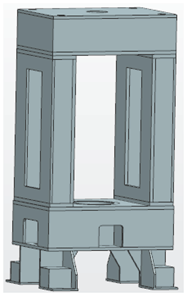
Topology optimization adjusts the shape of some components of the rack, which is only a preliminary structural optimization design. It can optimize the size of the rack under the condition of ensuring the performance of the rack, make clear the thickness of each component plate, and distribute materials more reasonably. The size optimization model of the rotary forging frame mainly adopts the 2D PSHALL unit, which is imported into the three-dimensional simplified model of the frame in HyperMesh to extract the middle surface, and then the topological repair treatment is carried out for each unit to get the shell model of the frame as shown in Fig. 23.
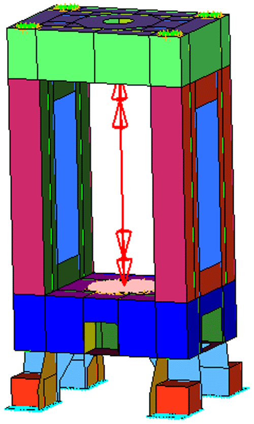
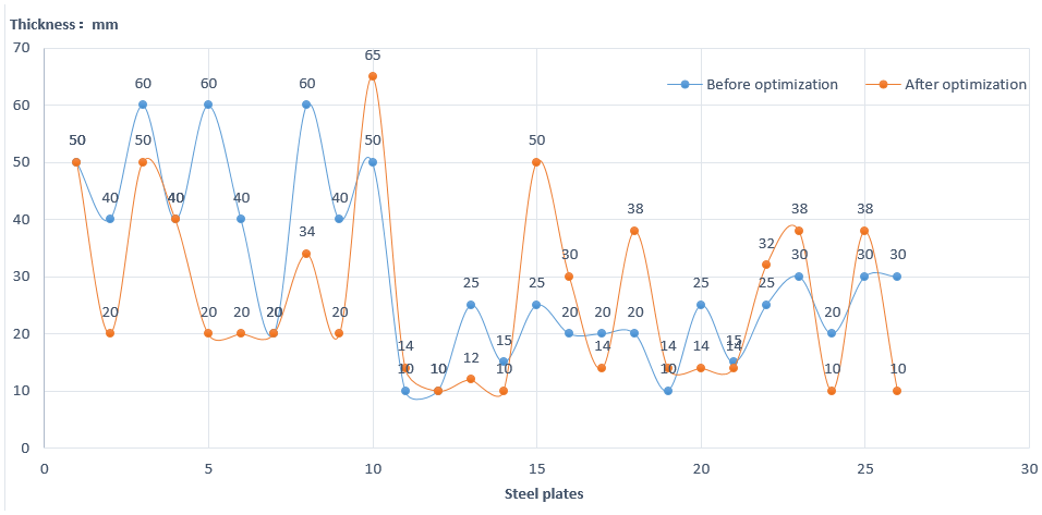
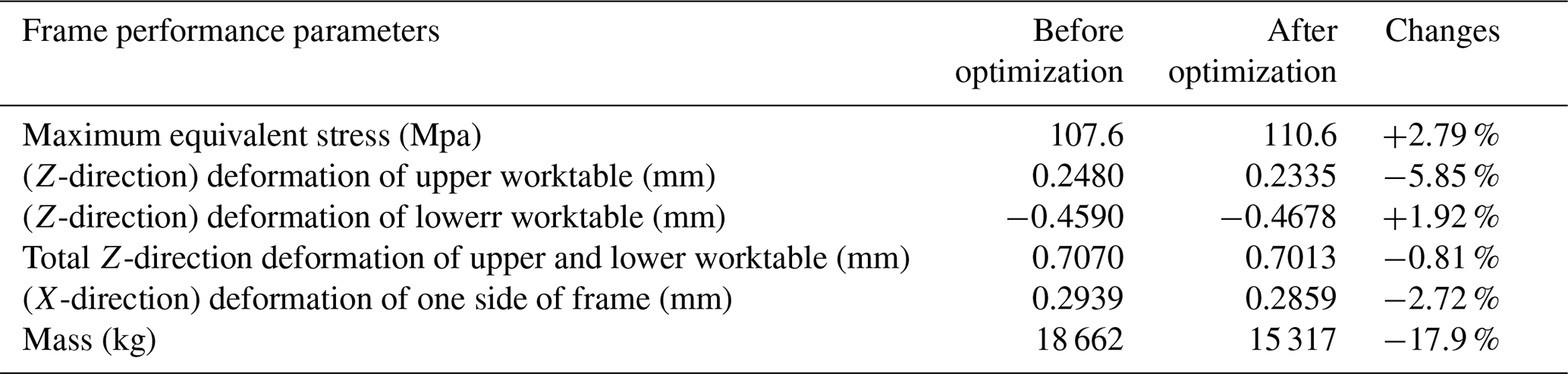
Table 2Performance comparison of double roll rotary forging machine frame before and after size optimization.
In the construction of the size optimization model of the frame, the plate thickness of the component plate unit is taken as the design variable, the initial value of each plate thickness, the upper and lower limits of the allowable plate thickness range are given in turn, and the minimum mass of the whole body is taken as the objective function to analyze the size optimization of the frame. After five iterations, the output of each plate thickness can be obtained by opening the result file. The results are given in turn, and the minimum mass of the whole body is taken as the objective function to analyze the size optimization of the frame. After five iterations, the output of each plate thickness can be obtained by opening the result file. The results are shown in the Fig. 24. The sequence is S1, S2, S3, Z1, Z2, Z3, Z4, X1, X2, X3, ss1, ss2, ss3, ss4, ss5, ss6, zz1, xx1, xx2,xx3, xx4, xx5, d1, d2, d3, d4. Considering the accuracy of actual machining, the results are rounded.
According to the values in the table above, the thickness of each plate in the model of rotary forging machine is readjusted, and the optimized model is obtained. Then, the finite element analysis of the adjusted double roll rotary forging frame is established again, and the performance before and after the size optimization is compared to get Table 2.
In terms of strength, the maximum stress of the frame increases by 2.79 % to 110.6 Mpa, but it is less than the allowable stress of Q235-A material, which conforms to the design; the strain changes in all directions of the machine frame are also small. In terms of weight, the overall mass of the frame changed from 18 662 to 15 317 kg, decreased by about 17.9 %.
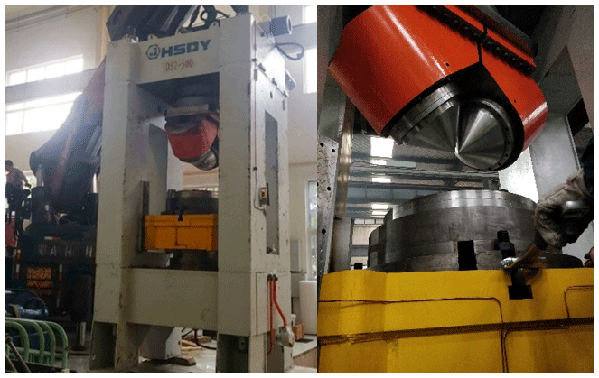
Based on the above optimization model and the optimized data, a double roll rotary forging machine was developed with the Huangshi Forging and Pressing Company of China, as shown in the Fig. 25. It is mainly used for the forming of spiral bevel gears. Figure 26 shows the shape of spiral bevel gear before and after forming.
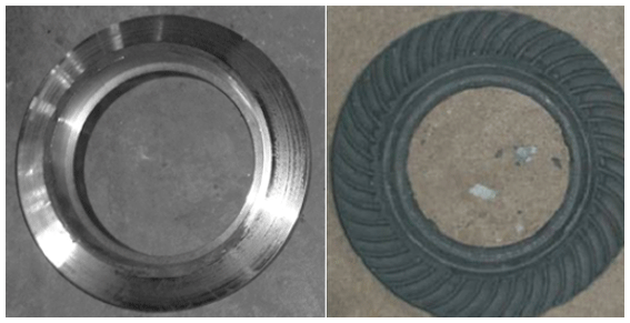
The microstructure of spiral bevel gear is composed of ferrite F and pearlite P, which is a kind of high-strength low-carbon steel. Because before and after optimization, the quality of parts formed by rotary forging machine can not be identified from the surface. In order to intuitively compare the influence of the frame before and after optimization on the parts formed by rotary forging, the heat treatment process will be adopted here. After isothermal normalizing, the density of the grain was observed, and the microhardness of the gear was measured by HX1000 Vickers microhardness tester. Furthermore, the influence of rotary forging machine on the forming quality of parts before and after optimization can be compared. Take samples of the formed spiral bevel gear at the top, middle, root and bottom of the gear respectively, and then observe the grain structure by metallographic test, as shown in Figs. 27 and 28.
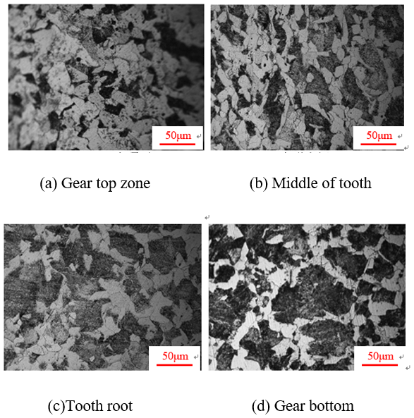
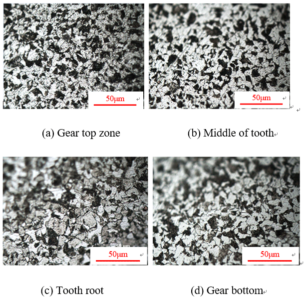
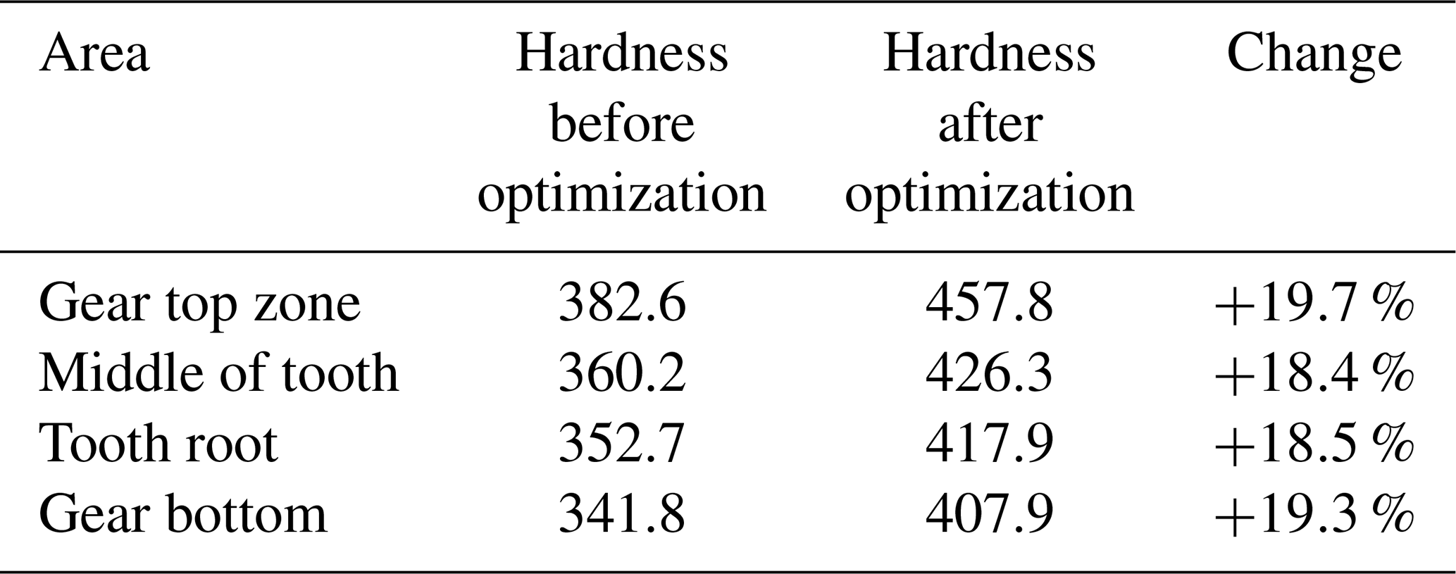
It can be seen from the microstructure that the quality of formed gear is greatly different before and after the optimization of rotary forging machine frame. After optimization, the grain of gear is finer. The distribution of ferrite and pearlite is uniform, which can improve the strength, plasticity and wear resistance of parts. After that, the hardness of each area of the gear shall be measured, and the average value of each area shall be taken after 5 times of measurement. The data obtained is shown in Table 3. It can be seen from Table 3 that the hardness of each area of the formed gear is improved before and after optimization of the rotary forging machine. After optimization, the hardness of each area of the gear is increased by nearly 20 %. In conclusion, the optimization scheme for the rotary forging machine body is reasonable.
In this paper, the structure optimization of the double roll rotary forging machine body is studied. The sensitivity analysis provides the basis for the subsequent size optimization, and the reasonable plate thickness is determined through the size optimization. Combined with the model and data, a new rotary forging machine is developed, and its forming quality is better through test analysis. The conclusions are as follows:
-
After topology optimization design, the performance of double roll rotary forging machine body meets the requirements. Compared with the frame before weight reduction, the overall mass is reduced by 1048 kg, i.e. 5.32 %, and the performance parameters are only slightly changed, which shows that the optimization scheme of the preliminary design is reasonable.
-
Using the influence law of each component plate of the frame on its performance, and using the optimization analysis method, the reasonable structure size combination meeting the requirements of stiffness and strength performance and with small mass is explored.
-
After the size optimization of the frame, the change of strength and rigidity of machine frame is small, and the mass is 17.9 % lower than the weight of the frame after the topology optimization.
-
Combined with the optimized model and data, the double roll rotary forging machine is developed, which is tested and verified. It is found that the forming quality of the workpiece is better, the grain size of the workpiece is refined and the hardness is improved,which shows that the optimization scheme is reasonable.
Data can be made available upon reasonable request. Please contact Chun Dong Zhu (zcdzcd6252@sina.com).
CDZ puts forward a method to optimize the body of double roll rotary forging machine, using finite element analysis and topology optimization; he did the final examine of the whole paper. LS studied the topological optimization method of the rotary forging machine body and the sensitivity analysis of the thickness to the machine frame. YZ and XL performed the experiment to verify the optimization scheme.
The authors declare that they have no conflict of interest.
The authors would like to thank the National Natural Science Foundation of China (No. 51875427) for the support given to this research.
This research has been supported by the National Natural Science Foundation of China (grant no. 51875427).
This paper was edited by Xichun Luo and reviewed by two anonymous referees.
Citipitioglu, A. M., Haj-Ali, R. M., and White, D. W.: Refined 3D finite element modeling of partially-restrained connections incuding slip, J. Constr. Steel Res., 58, 995–1013, https://doi.org/10.1016/S0143-974X(01)00087-6, 2002.
Deng, X., Hua, L., Han, X., and Song, Y.: Numerical and experimental investigation of cold rotary forging of a 20 crmnti alloy spur bevel gear, Mater. Des., 32, 1376–1389, https://doi.org/10.1016/j.matdes.2010.09.015, 2011.
Duan, Z. D. and Wu, J. J.: Topological optimization of frame of high speed hydraulic press based on generalized finite element modules, Appl. Mech. Mater., 47, 1828–1832, 2011.
Han, X. H. and Hua, L.: 3D FE modeling of cold rotary forging of a ring workpiece, J. Mater. Process. Tech., 209, 5353–5362, https://doi.org/10.1016/j.jmatprotec.2009.04.005, 2009.
Han, X. H., Hua, L., Zhuang, W. H., and Zhang, X. C.: Process design and control in cold rotary forging of non-rotary gear parts, J. Mater. Process. Tech., 214, 2402–2416, https://doi.org/10.1016/j.jmatprotec.2014.05.003, 2014.
Han, X. H., Hu, Y., and Hua, L.: Cold orbital forging of gear rack, Int. J. Mech. Sci., 117, 227–242, https://doi.org/10.1016/j.ijmecsci.2016.09.007, 2016.
Han, X. H., Qiu, J., and Hua, L.: Research on cold orbital forming of complex sheet metal of Aluminum Alloy, J. Manuf. Sci. Eng., 139, 1–9, https://doi.org/10.1115/1.4035124, 2017.
Hua, L. and Han, X. H.: 3D FE modeling simulation of cold rotary forging of a cylinder workpiece, Mater. Des., 30, 2133–2142, https://doi.org/10.1016/j.matdes.2008.08.045, 2009.
Jiao, M., Guo, X. H., and Wan, D. D.: Finite element analysis and lightweight research on the bed of a large machine tool base on hyperWorks, Appl. Mech. Mater., 121, 3294–329, https://doi.org/10.4028/www.scientific.net/AMM.121-126.3294, 2012.
Kim, J., Yoon, J. C., and Kang, B. C.: Finite element analysis and modeling of structure with bolted joints, Appl. Math. Model., 31, 895–911, https://doi.org/10.1016/j.apm.2006.03.020, 2006.
Liu, X., Zhu, C. D., Jiang, X., and Zhang, Y.: Influence of eccentricity of double eccentricity sleeves on the movements of swing head in rotary forging press, Mech. Sci., 10, 321–330, https://doi.org/10.5194/ms-10-321-2019, 2019.
Nam, C. H., Lee, M. C., Eom, J. G., Choi, M. H., and Joun, M. S.: Finite Element Analysis Model of Rotary Forging for Assembling Wheel Hub Bearing Assembly, Procedia Eng., 81, 2475–2480, https://doi.org/10.1016/j.proeng.2014.10.353, 2014.
Oh, H. K. and Choi, S.: A study on center thinning in the rotary forging of a circular plate, J. Mater. Process. Tech., 66, 101–106, https://doi.org/10.1016/S0924-0136(96)02502-2, 1997a.
Oh, H. K. and Choi, S.: Ductile fracture in the central region of a circular plate rotary forging, J. Mater. Process. Tech., 68, 23–26, https://doi.org/10.1016/s0924-0136(96)02522-8, 1997b.
Samoyk, G.: Investigation of the cold orbital forging process of an AlMgSi alloy bevel gear, J. Mater. Process. Tech., 213, 1692–1702, https://doi.org/10.1016/j.jmatprotec.2013.03.027, 2013.
Strano, M., Monno, M., and Rossi, A.: Optimized design of press frames with respect to energy efficiency, J. Clean. Product., 41, 140–149, https://doi.org/10.1016/j.jclepro.2012.10.017, 2013.
Wang, G. C. and Zhao, G. Q.: Simulation and analysis of rotary forging a ring workpiece using finite element method, Fin. Elem. Anal. Des., 38, 1151–1164, https://doi.org/10.1016/S0168-874X(02)00056-2, 2002.
Zhang, M.: Calculating force and energy during rotary forging proceedings, in: The Second International Conference On Rotary Metalworking Processes, Stratford on Avon, UK, 115–124, 1982.
Zhu, C. D., Guan, Q., and Wang, H.: Twin symmetry roll axial rolling: new method of plastic forming profiles demonstrated using manufacture of spiral bevel gears, Ironmak. Steelmak., 38, 211–217, https://doi.org/10.1016/j.triboint.2011.06.034, 2011.
Zhu, C. D., Jiang, X., and Dai, T. L.: Research on technology of twin rollers rotary forging of spiral bevel gears, Ironmak. Steelmak., 42, 632–640, https://doi.org/10.1179/1743281215Y.0000000019, 2015.
- Abstract
- Introduction
- Technical principle of double roll rotary forging and Composition of double roll rotary forging machine
- Optimum design of machine frame
- Test verification
- Conclusions
- Data availability
- Author contributions
- Competing interests
- Acknowledgements
- Financial support
- Review statement
- References