the Creative Commons Attribution 4.0 License.
the Creative Commons Attribution 4.0 License.
 | 15 Feb 2019
Design and dynamic analysis of metal rubber isolators between satellite and carrier rocket system
Xibin Cao
Cheng Wei
Jiqiu Liang
Lixu Wang
To achieve mobility and rapid-response, vehicles are used to launch satellites, and such systems will inevitably undergo random vibrations caused by uneven ground excitations. However, cameras or other high-precision satellite payloads cannot withstand such harsh mechanical environment in the absence of isolators. Hence, in the present paper, due to the advantages of the superior damping properties of metal rubber (MR), we designed MR structures to absorb vibrations. Correspondingly, the dynamical behaviours of the integrated system were comprehensively analysed to ensure that vibrations would not cause the payloads to collide with the fairing. In addition, the effects of geometric parameters of the isolated structures on the vibration properties of the system were investigated. This work provides a feasible design method of using simple MR structures, instead of very complicated isolators, for a mobile satellite launching system moving on rough roads.
- Article
(3348 KB) - Full-text XML
- BibTeX
- EndNote


Metal rubber (MR) is a kind of homogeneous elastic multi-gap material made of wires with polymer winding structures. It has advantages of light weight, anti-aging and corrosion resistance, especially excellent performances in hazardous environments (e.g., in vacuum, extreme high/low temperature environments) (Ma et al., 2013; Wang et al., 2010; Cao et al., 2012). Hence, MR products have received increasing attention and have been widely applied for isolation and noise reduction in the aerospace and aeronautic industry.
For the integrated design of a satellite, rocket and its mobile launch vehicle, it should be considered that the system will undergo random vibrations caused by uneven ground excitations during transportation (Wang et al., 2017a). The system design should prevent the satellite, camera and other payloads from damages due to the harsh mechanical environment. For this reason, it is necessary to employ isolation techniques to reduce the vibration of the payload.
Vibration isolation is a technology used to reduce vibrations by employing padding or mechanisms between excitation sources and payloads. Vibration isolation methods are generally divided into two categories: passive and active isolations. Passive isolation usually adjust the stiffness and damping of isolation structures to reduce vibrations via unpowered and uncontrolled mechanisms or rubber pads. Active isolation employs measure and control devices, and has excellent characteristics in low frequency bands and resonant frequencies, but the mechanisms have lower reliability due to the complexity of components (Bishop, 1958).
Nevertheless, MR structures can be applied in passive isolation to spacecraft to acquire high reliability because they have the advantages of both metal and rubber and we can obtain expected vibration isolation performances. Johnson (1995) gave a brief review of techniques for designed-in passive damping method, discussed the method based on viscoelastic materials, and analyzed the advantages of this method when applied to a stiffened panel under acoustic loading. Holtz (2010) designed an air-spring coupled with an auxiliary volume for articulated and rigid-frame dump trucks based on passive damping. Yao et al. (2002) designed an MR damper working in a flow mode, and a semi-active control strategy was validated for both the passive control and constant control methods. Mashayekhi and Vahdati (2009) designed a single pumper fluid mount and used a bond graph modeling technique to illustrate the effects of the vibration absorber. Kwon et al. (2017) designed a passive isolator with a pseudo-elastic SMA mesh washer to achieve a good vibration isolation performance that effectively prevented micro-disturbances from a jitter source in a launch environment. Ibrahim (2008) performed a comprehensive assessment of advances in nonlinear passive isolators, including traditional and non-traditional systems. Troynikov adn Moskalev (2014) analyzed the elastic and strength properties of an MR material based on similarity theory and dimensional analysis. By using finite element analysis (FEA), Putra et al. (2014) obtained static stress and strain responses of a laminated MR spring. Norfarizan et al. (2016) analyzed the dynamic performance of a laminated MR spring isolator and correspondingly got the transmissibility ratio from the displacement changes. Yan et al. (2014) studied the energy dissipation of a ring-like MR isolator and experimentally verified the hysteresis loops of the force and deformation. These studies of passive MR isolators or MR materials concentrated on the design of isolators and static analysis of MR elements, but lacked detailed dynamic analysis, especially for those considering coupled interactions between payload and isolator.
In this paper, for an integrated design system of a satellite and carrier rocket, we presented the design method of MR structures at multiple points to absorb satellite vibrations caused by excitations of the moving rocket vehicle. Correspondingly, the dynamical stress-displacement response of the integrated system were analyzed based on the kinematics presented in our previous work (Wang et al., 2017a, b) to ensure that the vibrations would not cause the satellite to collide with the enclosing fairing, which provides a feasible design method utilizing simple MR structures instead of complicated active structures. Finally, the simulation was addressed to validate the efficiency of the proposed design method.
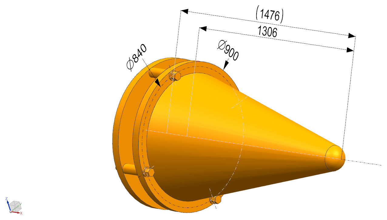
Considering the superior vibration damping performance of MR, we designed simple MR components in connection with the explosive bolts, satellite and rocket to reduce the vibration of the satellite, especially the camera, and other payloads. The general structures are shown in Fig. 1.
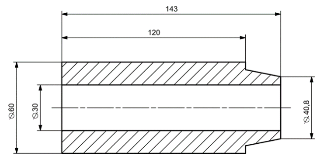
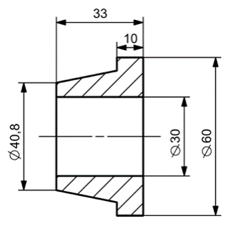
The connection of the bolts through reamed holes is shown in Fig. 2 (the details of the explosive bolts are simplified). There is a pair of MR elements, i.e. Element 3 between the explosive bolt 1 and the satellite flange 4, and Element 5 between the rocket flange and the satellite flange. There are no threaded connections between the satellite flange and the explosive bolts. The geometries of the MR components pair are shown in Figs. 3 and 4.
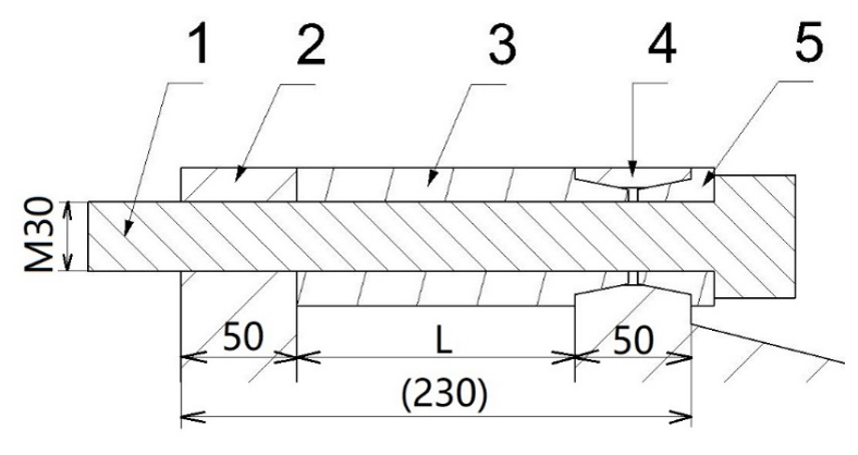
Figure 2Connections of the MR elements pair. 1 – Explosive bolt, 2 – Rocket flange, 3 – MR element, 4 – Satellite flange, 5 – MR element.
This design references to the theory of linear free vibration model of cantilever. The bolts are taken as cantilevers and the satellite is treated as the concentrated mass of the free end. The MR elements are employed as damping elements to further reduce vibrations while providing supports. According to vibration theories, the natural frequency for a single bolt cantilever is:
where EI is the bending stiffness, mm the mass applied on the free end, mc–eq the equivalent mass of the cantilever and the MR elements, and l the length of the cantilever. Although the system designed in this paper is not a free vibration system, Eq. (1) can provide a conceptual model for the isolation design. Obviously, the isolation effect of the designed structures will change with length L, shown in Fig. 2, and the number of explosive bolts and MR elements.
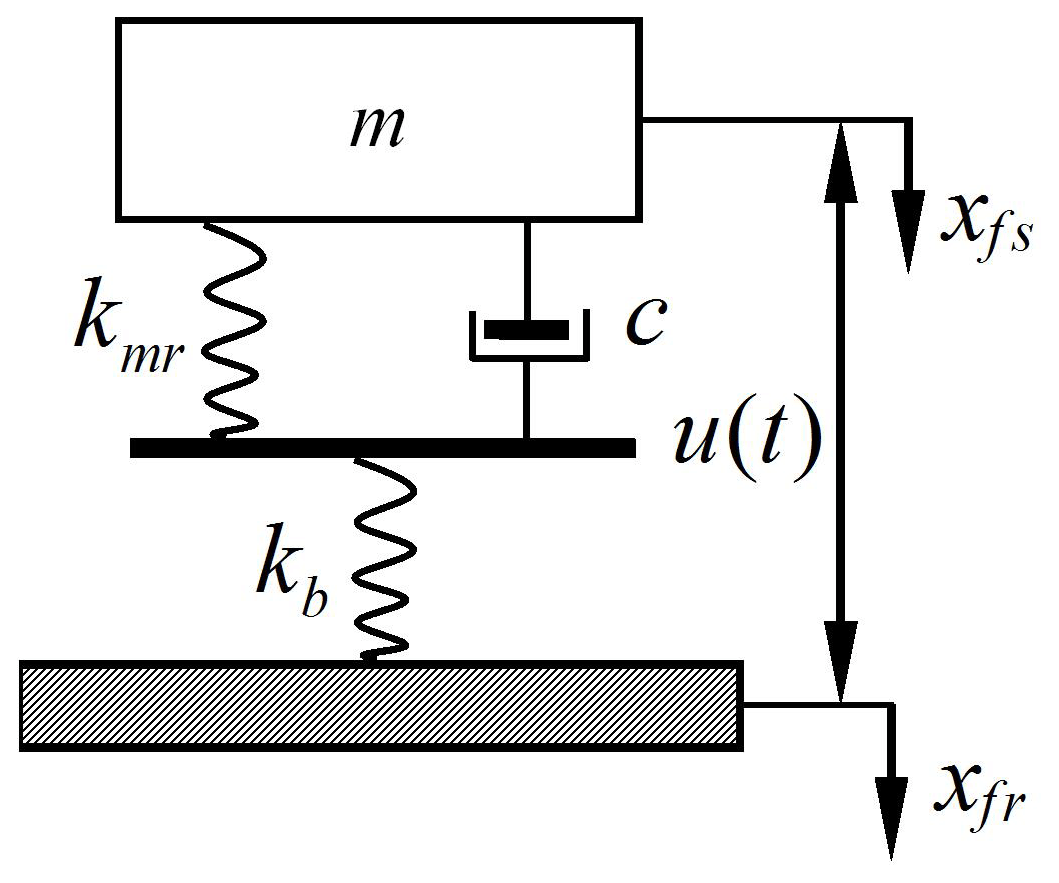
In the following, we will discuss the factors that affect the vibration of the system. First, suppose a dynamical model of the satellite and rocket system with a single explosive bolt and MR component, which can be simplified as shown Fig. 5. The explosive bolt is taken to be an elastic spring, and the MR element is simplified as a spring-damping element. Then, the explosive bolt and corresponding MR element are in series. m denotes the mass of the satellite, namely the loading part; c the damping ratio of the MR; kmr the stiffness of the MR; kb the stiffness of the explosive bolt; xfs(t) the displacement of the satellite's flange; xfr(t) the displacement of the rocket's flange; u(t) the relative displacement between the flanges of the satellite and rocket, which is the same as that between the satellite and the fairing. For the real system, there is a group of these isolation components in parallel.
Letting kb=αkmr, we then describe the system by the following two dynamical equations:
According to Eqs. (2) and (3), we have
Taking the derivative once with respect to time t, we obtain
Substituting Eq. (5) into Eq. (1), we obtain
Suppose , and Eq. (6) can be rewritten as:
Therefore, the relative transfer rate of this system is:
where ω is the excitation frequency, the natural frequency of the system is , and the damping ratio is . Since the stiffness of explosive bolts is much greater than that of MR components, i.e. kb≪kmr and α≫1, the dynamical equation and relative transfer rate can be simplified to:
and
Hence,
where E indicates calculating the mean value, Su is the power spectral density of relative displacement between the satellite and rocket flanges, and S0 is the power spectral density of the satellite's accelerations. Employing the residue theorem, we can obtain E[u2(t)] for the system with four explosive bolts and MR components.
Usually, we can take 3σ[u(t)] as the minimum assembly clearance, that is, over the long run, we expect that the probability that the satellite and fairing will not collide is 99.7 % if the process is a stable normal distribution with a mean square error of σ. However, there is in fact a deviation from the target value. Considering a 1.5σ deviation, 3σ corresponds to a 93.32 % survival rate, and 6σ corresponds to a 99.9996 % survival rate. At the equilibrium position, E[u(t)]=0. Therefore, we obtain the minimum design clearance δmin between the satellite and fairing:
or
The design value of δmin depends on S0, ξ and ωn of the system. Considering a 1.5σ deviation, 3σ or 6σ value can be adopted as the reference design value of the clearance between the satellite and fairing.
Referring to our previous papers (Wang et al., 2017a, b), we have obtained the dynamical behavior of the system without the damping MR components when driving on a Grade E road. The deformations of the rocket and satellite are relatively small compared with those of the explosive bolts. Hence, for the finite element analysis we can take the satellite and rocket as rigid bodies, and the corresponding acceleration can be applied to the center of mass of the rocket flange as the excitation to estimate the satellite's response. Here, the acceleration response of the satellite is mainly due to the vertical accelerations caused by the roughness of the road.
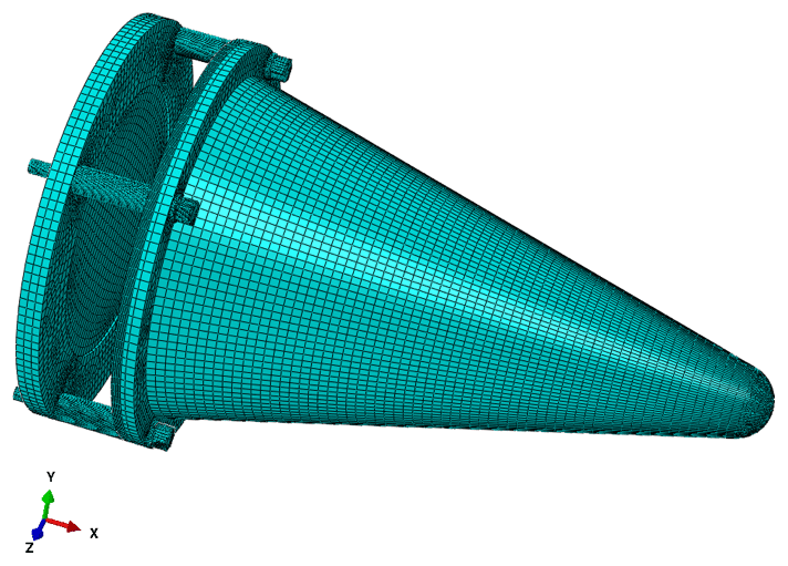
To obtain the stress responses of the explosive bolts and MR components during vibrations under stimulations, we modeled the assembly of the rocket flange, explosive bolts, satellite, and MR elements. The FE model with hexahedral meshes is shown in Fig. 6. The local meshes around the bolt holes and MR elements were refined to get the mesh convergence (the details of which we did not provide here). The properties and convergent meshes of each element are listed in Table 1. For the MR elements, the material was set to obey a multi-linear kinematic hardening rule to approximate the stress-strain response in Fig. 7.
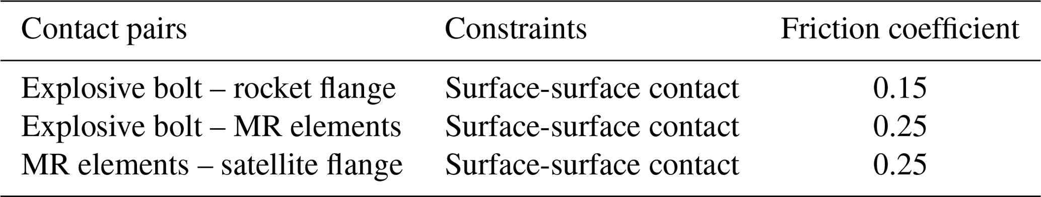
The assigned contacts and constraints of the rocket-satellite system are listed in Table 2. In addition, the satellite and rocket are defined as rigid bodies because their deformations are much smaller than those of the other connection parts. For the reaming-hole bolt connections, the pretension force was chosen to be 7 kN according to the strength of the MR, which is relatively lower than that of the explosive bolts without MR isolations.
Table 1Properties and convergent meshes.
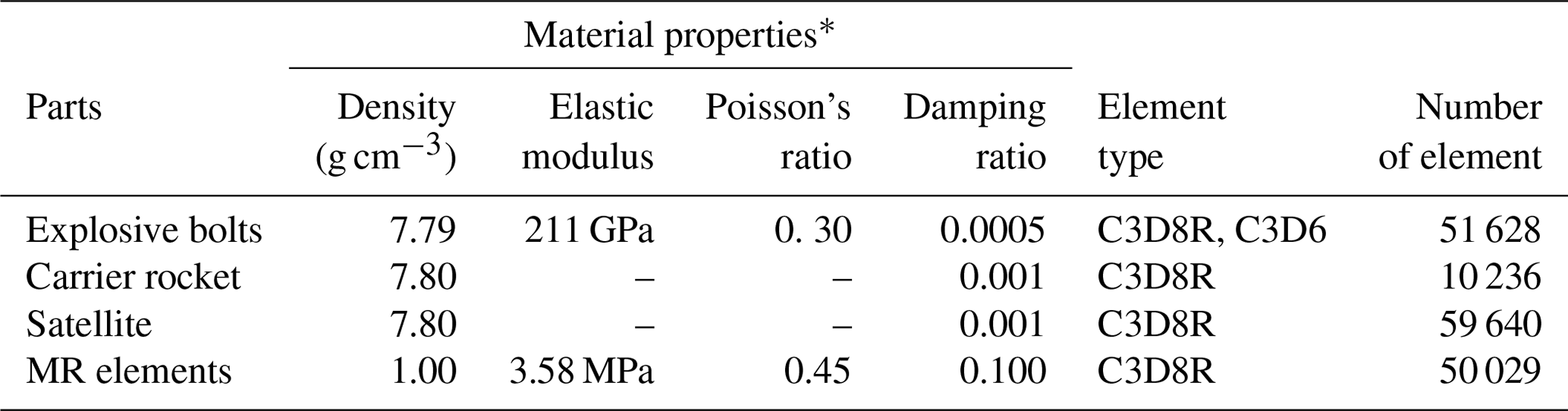
* Wang et al. (2010) and Cao et al. (2012)
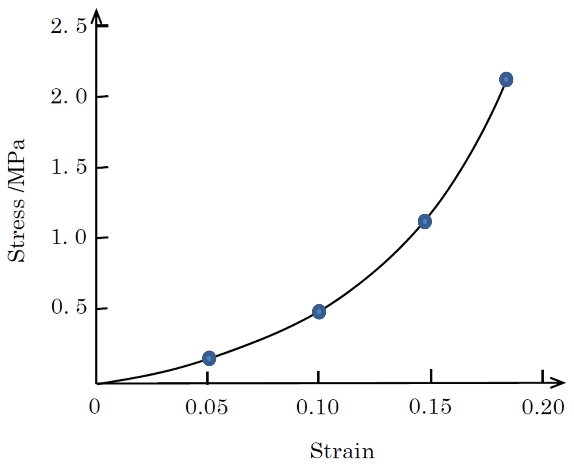
Figure 7Stress-strain response adopted in FE analysis. The points are in the data table of the multi-linear kinematic hardening rule. The data are from Cao et al. (2012).
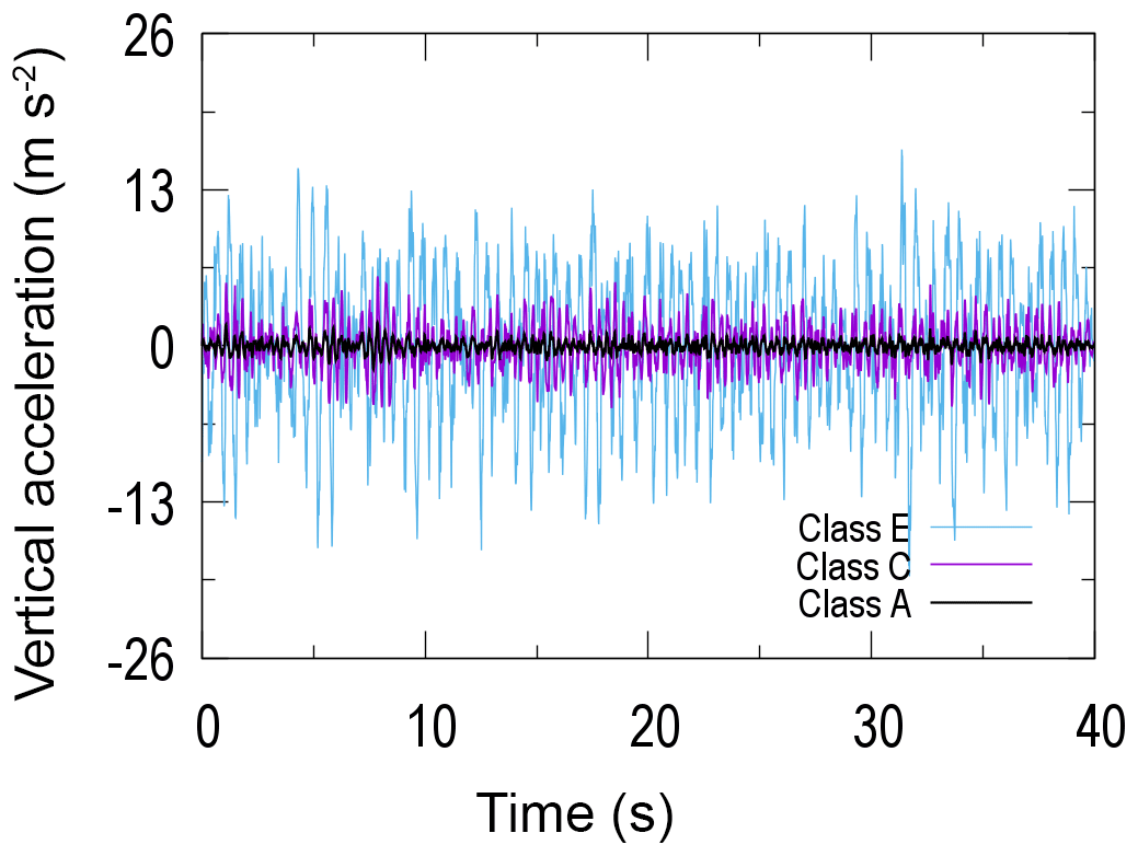
Most highways in China belong to Classes A, B, and C (Wang et al., 2017a). Class A is an ideal condition, Class C a common one, and Class E a severe one. Therefore, we study the dynamical response of the system in maneuvers on a class E road, which provides the most dangerous condition for the impact and fatigue failure assessments.
When the vehicle drives on a class E road, the satellite vibrates because of the road's roughness, and the vertical vibration is the most significant component, as seen in Fig. 8. The generated loads of the road's roughness, the responses of the explosive bolts and satellite, and additional details about the modeling system can be found in our previous work (Wang et al., 2017a, b).
Vibrations during delivery may cause the fairing and satellite to impact and result in the failure of the satellite. Therefore, based on the dynamical analysis with the finite element method, this paper focuses on the safety assessment of the multi-point isolation system during transportation.
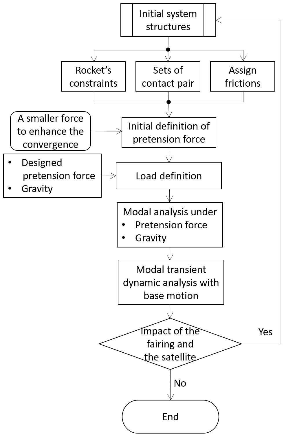
The scheme of the safety analysis of the system is stated in Fig. 9. The basic idea and steps of the dynamical analysis are as follows:
-
Perform a modal analysis with the Lanczos algorithm to determine the frequencies of the first four mode shapes.
-
Apply the main simplified loads in the vertical direction of the satellite-rocket system.
-
Perform a modal transient dynamic analysis under the base motion of the vertical acceleration of the rocket body in Fig. 7 to investigate the structural response under loading via the modal superposition method based on the modal analysis results.
-
Estimate the maximum clearance between the fairing and satellite to ensure that no impact occurs.
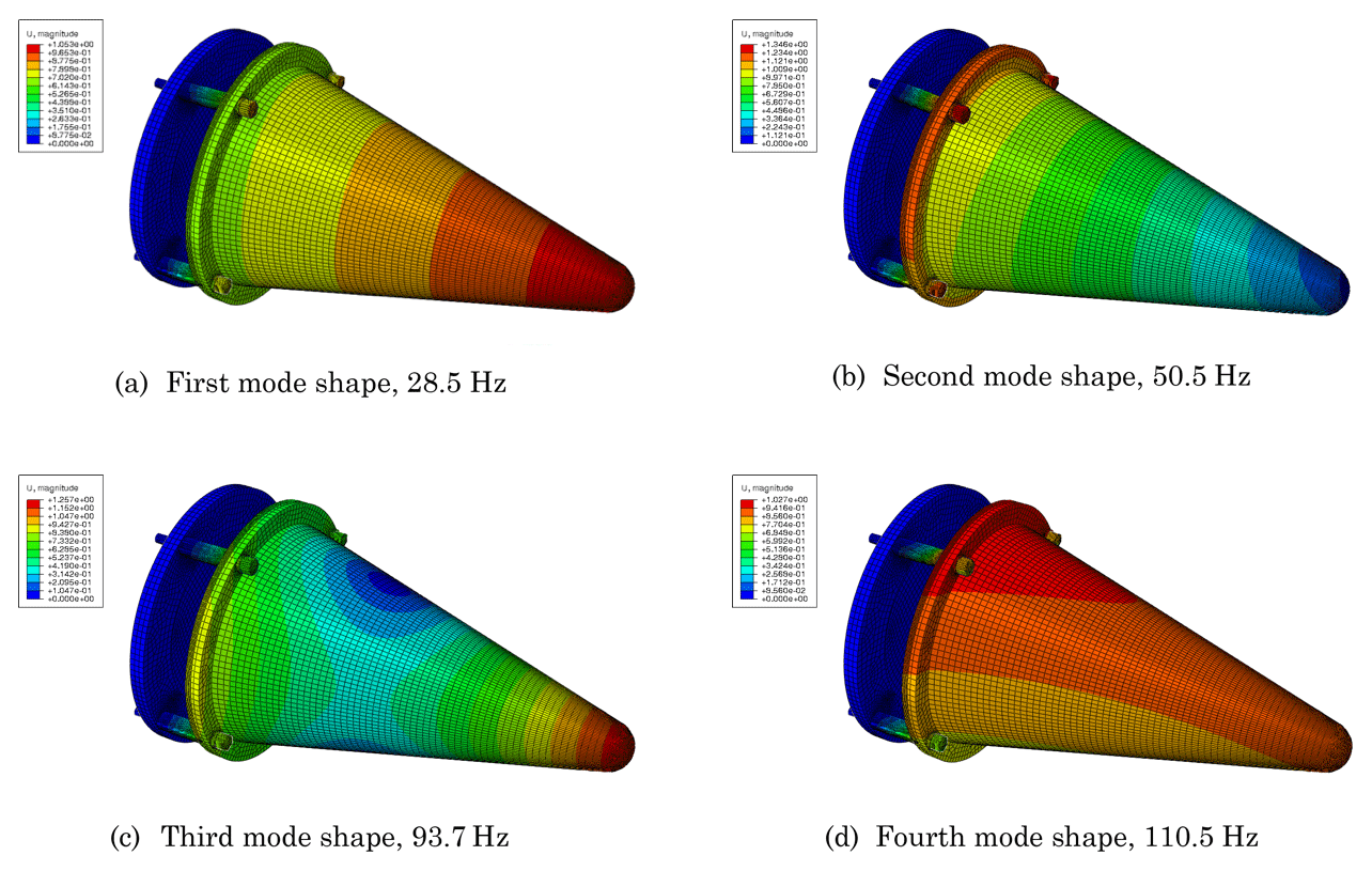
Through the modal analysis of the entire system under the above sets, we achieved the vibration response properties. Figure 10 shows the first four mode shapes, the corresponding frequencies of which are 28.5, 50.5, 93.7 and 110.5 Hz, respectively.
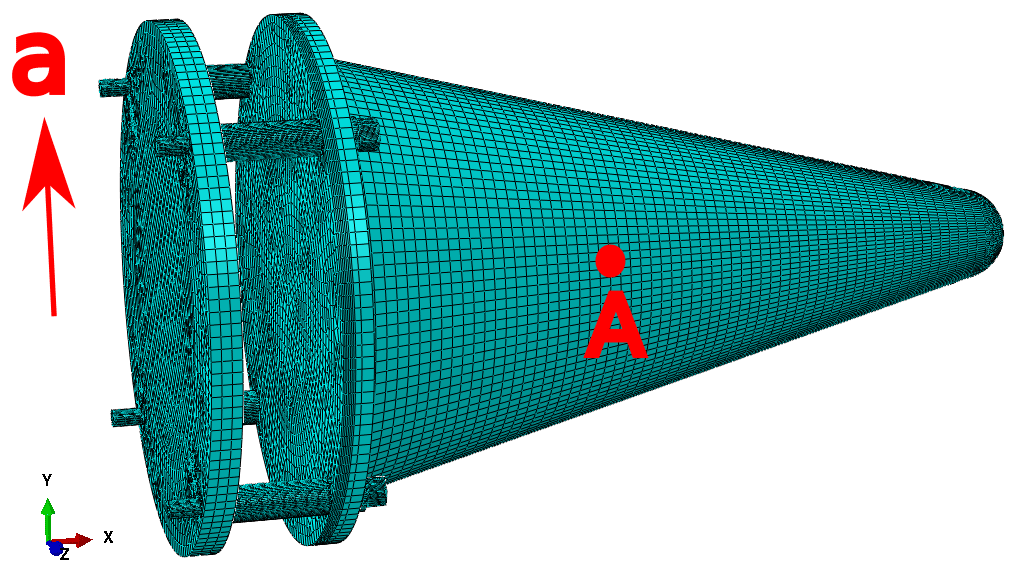
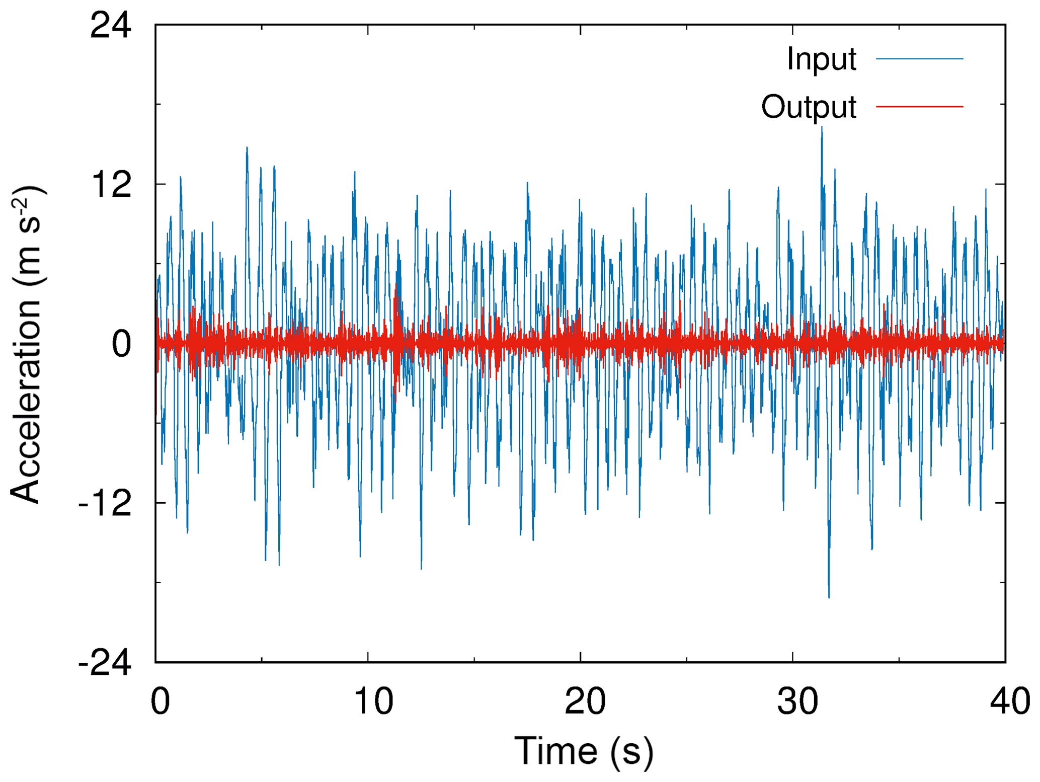
After the modal analysis, the modal transient dynamic method was selected to analyze the response of the satellite under maneuver on the class E road. In order to improve the efficiency of the simulations, the system was simplified to a single degree-of-freedom one, and the vertical acceleration of the rocket body shown in Fig. 8 was applied to the centroid of the rocket's flange, as shown in Fig. 11. The analysis time was set to 40 s and the relative acceleration response of the satellite's centroid point A was extracted, as indicated by the red curve in Fig. 12. The blue input curve indicates the acceleration under the E-class road without the metal rubber isolation components. Comparing the input and output loading curves, it can be seen that the amplitudes of the satellite's acceleration response were significantly reduced by the designed multi-point MR isolation structures.
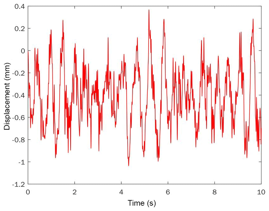
The vertical displacement curve of the satellite relative to the fairing was plotted in Fig. 13. The maximum value is approximately 1.036 mm at the top point of the satellite, and the mean square error is 0.266 mm. Based on the dynamic analysis, considering a 1.5σ deviation, 3σ=0.798 mm with a 93.32 % survival rate, and 6σ=1.596 mm with a 99.9996 % survival rate.
At the same time, with the model of Eq. (11), we estimated E[u2(t)]=0.0847 mm for the system with four explosive bolts and MR components. Considering a 1.5σ deviation from the target value, we got mm with a 93.32 % survival rate and mm with a 99.9996 % survival rate.
For the design of the clearance between the satellite and fairing, the results from the dynamic simulations with the finite element method and those from the estimation model of Eq. (11) agreed very well. Thus, with the MR isolation components presented in this paper, the original designed clearance of 1 cm between the satellite and fairing is sufficiently large to prevent the satellite and fairing from impacting. The proposed design method yielded relatively safe results with much higher reliability.
5.1 Distance parameter L between the satellite and rocket
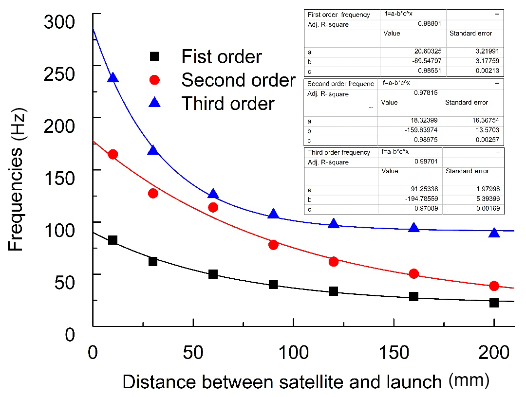
The lengths of explosive bolts and metal rubber Element 3 were adjusted to change the distance L between the satellite and rocket. When increasing L, the stiffness of the system will decrease. According to modal analysis results, Fig. 14 presents the asymptotic exponential decays of vibration frequencies with the increasing distance L. When L reaches 120 mm, the curve approaches a relatively steady region. The associated parameters of the asymptotic exponential decay equations are given in the figure for the first three order vibrations.
5.2 Number of explosive bolts and metal rubber components
Another critical design parameter is the number of explosive bolts and MR components, which affects the system stiffness obviously. Figure 15 reflects the vibration frequencies of the different mode shapes varying with the number of explosive bolts and MR components. The system vibration frequency of each order increases with the number of bolts and MR components. In addition, the variation law is nearly linear. The first four mode shapes are similar to those shown in Fig. 9 and are not provided here.
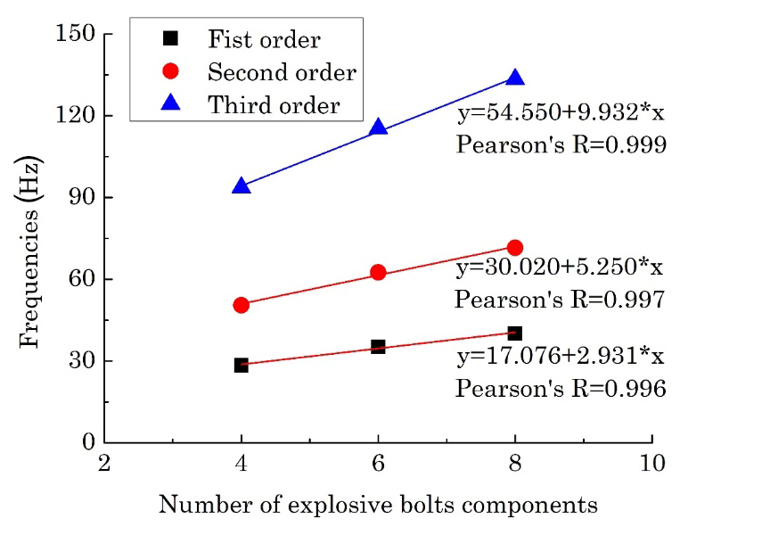
Figure 15Vibration frequencies of the satellite with varying numbers of explosive bolts and MR components.
According to Sect. 5, when designing the metal rubber isolation components, the number of bolts and MR pairs and the length L should be matched so as to decrease the system's vibration frequency. Another point is to avoid the frequency bands of the motivations.
This paper presents the design of a multi-point vibration isolation system by using MR components in connection with the explosive bolts, satellite and rocket to reduce the stiffness and improve the damping performance of the system. The main conclusions are as follows.
When the vehicle moves on the E class road, the dynamic simulation using the finite element method yields a maximum relative clearance of 1.04 mm between the satellite and fairing, and the mean square error is 0.266 mm. Considering a 1.5σ deviation, 3σ=0.798 mm with a 93.32 % survival rate, and 6σ=1.596 mm with a 99.9996 % survival rate. The simulation results for different survival rates agreed well with the estimated value by using Eq. (11) considering a 1.5σ deviation from the target value.
The system stiffness and consequently the first-order frequency decreased with the increasing distance between the satellite and rocket. The multi-point MR isolation system then performs better. The empirical exponential decay equations for the vibration frequencies vs. distance L between the satellite and rocket are given in Fig. 14.
The system's stiffness and consequently the first-order frequency decrease with the numbers of explosive bolts and MR components between the satellite and rocket. The multi-point isolation system then performs better. Figure 15 gave the linear relationship between the vibration frequencies of the satellite and the number of explosive bolts and MR components.
No further data need to be presented, all our research data are included in this paper and in bibliography (Wang et al., 2017a, b).
XC proposed the design method of MR isolators. CW constructed the dynamic model of the whole system. JL analyzed the isolation performance of the MR structures. LW helped modeling the road loading disturbance.
The authors declare that they have no conflict of interest.
The authors would like to thank the support of the National Natural Science
Foundation of China (No. 51475396, No. 11772102), the National Basic Research
Program of China (No. 2013CB733004), Natural Scientific Research Innovation
Foundation in Harbin Institute of Technology (No. 30620150071) and the Open
Fund of National Defense Key Discipline Laboratory of Micro-Spacecraft
Technology (HIT.KLOF.MST.201703).
Edited by:
Jinguo Liu
Reviewed by: two anonymous referees
Bishop, R. E. D.: Mechanical Vibration, Nature, 182, 1581–1581, 1958.
Cao, F., Bao, H., Ren, G., and Fan, H.: Constitutive Model of Metal Rubber Material Based on Curved Cantilever Beam of Variable Length, J. Mech. Eng., 48, 61–66, 2012.
Holtz, M.: Modeling and Design of a Novel Air-spring for a Suspension Seat, J. Sound Vib., 329, 4354–4366, 2010.
Ibrahim, R. A.: Recent advances in nonlinear passive vibration isolators, J. Sound Vib., 314, 371–452, 2008.
Johnson, C. D.: Design of Passive Damping Systems, J. Vib. Acoust., 117, 171–176, 1995.
Kwon, S. C., Jo, M. S., and Oh, H. U.: Experimental Validation of Fly-Wheel Passive Launch and On-Orbit Vibration Isolation System by Using a Superelastic SMA Mesh Washer Isolator, Int. J. Aerospace Eng., 2017, 5496053, https://doi.org/10.1155/2017/5496053, 2017.
Ma, Y., Liang, Z., Wang, H., Zhang, D., and Hong, J.: Theoretical and experimental steady-state rotor dynamics of an adaptive Air Film Damper with Metal Rubber, J. Sound Vib., 332, 5710–5726, 2013.
Mashayekhi, M. J. and Vahdati, N.: Application of Tuned Vibration Absorbers in Fluid Mounts, Shock Vib., 16, 565–580, 2009.
Norfarizan, S., Putra, A., Salim, M. A., and Ramlan, R.: Dynamic analysis of laminated rubber-metal spring using finite element method, Proceedings of Mechanical Engineering Research Day 2016, 210–211, 2016.
Putra, A., Norfarizan, S., Samekto, H., and Salim, M. A.: Static Analysis of a Laminated Rubber-Metal Spring Using Finite Element Method, Adv. Mat. Res., 845, 86–90, 2014.
Troynikov, A. A. and Moskalev, Y. A.: Elastic and strength properties of metal rubber material, Int. J. Eng. Technol., 6, 2276–2282, 2014.
Wang, H., Rongong, J. A., Tomlinson, G. R., and Hong, J.: Nonlinear static and dynamic properties of metal rubber dampers, International Conference on Noise and Vibration Engineering (ISMA), 1301–1315, 2010.
Wang, L., Zhao, T., Gang, T., Chen, L., and Tian, H.: Fatigue Assessment of Explosive Bolts Considering Vibration of Fixtures, Appl. Sci. 7, 440, https://doi.org/10.3390/app7040440, 2017a.
Wang, L., Liang, X., Zhao, Y., and Chen, L.: Dynamics analysis of a missile vehicle considering the pavement rouphness, The 8th IEEE CIS&RAM 2017, Ningbo, China, 19–21 November, 2017b.
Yao, G., Yap, F., Chen, G., Li, W. H., and Yeo, S. H.: MR Damper and its Application for Semi-active Control of Vehicle Suspension System, Mechatronics, 12, 963–973, 2002.
Yan, H., Zhang, W. J., Jiang, Y. H., and Chen, L.: Energy dissipation of a ring-like metal rubber isolator, Chinese Phys. B, 23, 198–201, 2014.
- Abstract
- Introduction
- Design of the MR isolation structures between the satellite and rocket
- Finite element (FE) modeling
- Dynamical analysis to prevent the impact of the fairing and satellite during transportation
- Design parameters of metal rubber components
- Conclusions
- Data availability
- Author contributions
- Competing interests
- Acknowledgements
- References