the Creative Commons Attribution 4.0 License.
the Creative Commons Attribution 4.0 License.
Numerical modeling and dynamic characteristics study of coupling vibration of multistage face gearsplanetary transmission
Xingbin Chen
Zhongyang Xu
Chune Zhu
A novel transmission with multistage face gears as the core component achieves variable speeds via differential gear shifting. Single/multistage coupled vibration models have been established in this study to derive the coupled vibration equation in order to accurately solve the load distribution between the meshing teeth and the vibration shock between the shifting stages in the transmission process, improve the transmission smoothness of the face gears during the shifting processing, suppress the resonance of face gears meshing, reduce the noise, and optimize the power transmission performance. The characterization relationships of the key parameters such as equivalent mass, rotational inertia, equivalent mesh stiffness, support stiffness, and meshing damping coefficient to dynamic characteristics were investigated. The linear and nonlinear dynamic characteristics of coupled vibration differential equations were solved. The influence rules of factors such as integrated transmission error, dynamic load, tooth surface friction, loading speed, and load on the transmission system were analyzed. The results of the study provide a theoretical basis for the expansion of field of application of transmission devices.
- Article
(16869 KB) - Full-text XML
- BibTeX
- EndNote
The mechanism of multistage face gears integrates the general advantages of most planetary transmission devices, and has a novel structure and flexible arrangement, which can be widely applied to high-speed or heavy-load fields such as automobiles, ships, and airplanes. The vibration characteristics of the device have a significant impact on the transmission stability and reliability. A significant research work has been conducted by domestic and foreign scholars to deeply understand the gear dynamic performance. Sakaridis et al. (2019) investigated the effect of the individual tooth inertia on spur gear dynamics. A lumped element model was developed, in which tooth and gear inertial properties were decoupled, with the incorporation of the meshing position and load dependent meshing stiffness and backlash (Sakaridis et al., 2019). Tatar et al. (2019) developed six degrees of freedom dynamic model of a planetary geared rotor system with equally spaced planets by considering the gyroscopic effects. The dynamic model was created using a lumped parameter model of the planetary gearbox and a finite element model of the rotating shafts using Timoshenko beams (Tatar et al., 2019). Liu et al. (2019) investigated an excitation pattern of the time-varying instantaneous center of the noncircular face gear drive system, wherein a torsional-lateral-axial coupled dynamic model of the noncircular face gear system was presented under the compound parametric excitations of the time-varying instantaneous center and mesh stiffness (Liu et al., 2019). Dadon et al. (2019) focused on the fault detection and characterization based on the vibrations in a spur gear transmission. The faults were thoroughly analyzed to understand the fault manifestation in the vibration signature and find condition indicators that were robust and sensitive to the existence and severity of the fault (Dadon et al., 2019). Yu and Mechefske (2019) defined two types of helical gear pairs based on the relationship between the transverse contact ratio and overlap the contact ratio, and proposed an improved analytical model using the slicing principle for the calculation of single mesh stiffness of helical gears (Yu and Mechefske, 2019). Ren et al. (2018) presented a novel and generalized bending-torsional-axial coupled dynamic model of a herringbone planetary gear train (HPGT) to investigate the dynamic floating performances with the application of the lumped-parameter approach. The variable step Runge–Kutta algorithm was utilized to compute the dynamic responses of the HPGT system (Ren et al., 2018). Saxena et al. (2018) performed an experimental study to discover the effect of gear pair contact on the modal behavior of an actual geared rotor system mounted on the rolling element bearings. The frequency response functions of the uncoupled and coupled geared rotor systems were measured to uncover the effect of gear pair contact on the natural frequencies of the system (Saxena et al., 2018). Dong and Hu (2018) established the bend-torsion coupling dynamics load-sharing model of the helicopter face gear split torque transmission system by using the concentrated quality standards, to analyze the dynamic load-sharing characteristics, which provided a theoretical basis and data support for its dynamic performance optimization design (Dong and Hu, 2018). Atanasovska and Hedrih (2018) used a model of a central centric collision of two fictive rolling disks, with radii equal to the radii of pitch diameters of coupled gears, in order to describe the vibro-impact dynamics of spur gears. A set of transmission error equations for the calculation of the disturbance angular velocity of the pinion was developed; the transmission error had a role of excitation of vibro-impact vibrations in the gear tooth contact (Atanasovska and Hedrih, 2018). L. N. Zhang et al. (2017) proposed a dynamic model of an N-stage power-split planetary gear set. Natural frequencies and vibration modes were obtained by solving the eigenvalue problem governed by the corresponding equations (L. N. Zhang et al., 2017). Chowdhury and Yedavalli (2017) developed analytical model for the linear vibration analysis of a pair of coupled spur geared shaft system. The model was a hybrid discrete-continuous one, wherein the gears were modeled as rigid disks mounted on the elastic shafts having transverse as well as torsional flexibilities, and supported by the rigid bearings. The non-dimensional governing equations along with the natural boundary conditions were developed using the Hamilton's principle (Chowdhury and Yedavalli, 2017). A. Q. Zhang et al. (2017) established the coupled lateral-torsional-axial vibration dynamical model of the planetary gear system under a generalized coordinate system using the shafting element method. The results indicate that the flexibility of ring-gear had a great effect on the natural frequency (A. Q. Zhang et al., 2017). Hmida et al. (2017) investigated a mechanical system composed of an electric motor, an elastic coupling, and one stage spur gear to analyze the dynamic behavior of elastic coupling, its influence on the natural frequencies, the vibrations, and the response of the system. A lumped parameter model of the corresponding system was developed to identify the natural frequencies and vibration modes (Hmida et al., 2017). Wu et al. (2017) set up a nonlinear vibration model of the gear system with multiple degrees of freedom, multi-gap, variable parameter, and bending-torsion coupling by using the mass-concentrated method for NN-type small tooth-difference planetary gear system. The nonlinear vibration differential equations deduced by Lagrange equation were solved with the fourth-order Runge–Kutta-Fehlberg method. MATLAB program was adopted to systematically analyze the vibration displacement and velocity response of the gears (Wu et al., 2017). Fernandez-Del-Rincon et al. (2017) presented a model that could simultaneously consider the internal excitations due to variable meshing stiffness (including the coupling among successive tooth pairs in contact, non-linearity linked with the contacts between surfaces and dissipative effects). The model could also simulate gear dynamics in a realistic torque dependent scenario. The proposed model combined a hybrid formulation for calculation of meshing forces with a non-linear variable compliance approach for bearings. The meshing forces were obtained by means of a double approach which combined numerical and analytical aspects (Fernandez-Del-Rincon et al., 2017). Bouslema et al. (2017) aimed at the application of a substructure methodology, based on the Frequency Response Function (FRF) simulation technique, to analyze the vibration of a stage reducer connected by a rigid coupling to a planetary gear system. The computation of the vibration response was achieved by using the FRF-based substructuring method. First of all, the two subsystems were separately analyzed and their FRF were obtained. Then, the coupled model was analyzed indirectly using the substructuring technique (Bouslema et al., 2017). Zhang et al. (2016) first presented a translational-rotational dynamic model of a two-stage closed-form planetary gear set under consideration of the rotational and translational displacements to investigate the dynamic response and avoid resonance (Zhang et al., 2016). Xiao et al. (2016) proposed a coupling dynamic model for multi-stage planetary gears train (PGT) based on the gearing theory and Lagrange equation. The modified transverse-torsional model was established in the rotating Cartesian coordinates by using the lumped-parameter method; thus, the model was more accurate than the purely torsional model for describing the physical dynamics (Xiao et al., 2016). Liu et al. (2016) performed a systematic analysis of the dynamics of a helical face-gear system with 8 degrees of freedom under complex excitation. The nonlinear dynamic system was solved using the Runge–Kutta method. The bifurcation and dynamic load characteristics of the system were identified from a series of diagrams. The effect of multi-factor on the bifurcation diagrams was also analyzed (Liu et al., 2016). Cai and Lin (2017) presented a generalized nonlinear dynamic model based on Lagrange Bond graphs to study the nonlinear dynamic characteristics of a curve-face gear drive, and indicated that the vibration response of the curve-face gear is more complex than that of the face gear due to the influence of external excitation (Cai and Lin, 2017). Lin et al. (2015) established a nonlinear dynamic model of the twisting vibration of the orthogonal curve-face gear transmission, and presented the nonlinear vibration differential equation. Using the fourth-order Runge–Kutta numerical integral method to solve the equation with MATLAB, the dynamic response of orthogonal curve-face gear transmission was obtained (Lin et al., 2015). Peng and DeSmidt (2015) established a structural dynamics model for the torsional vibration of gearboxes containing a face-gear drive by considering the flexibilities of gear teeth and transmission shafts. The face-gear mesh-induced parametric instability phenomena was numerically explored via Floquet theory for various shaft characteristics and system inertia distributions (Peng and DeSmidt, 2015). Hu et al. (2015) proposed a fourteen degree-of-freedom (DOE) lumped parameter dynamic model considering the coupled translation-rotation vibration. The jump phenomenon, periodic window, doubling periodic bifurcation and chaotic behavior of the system were observed and a path to chaotic motion through doubling period bifurcation motion was also observed (Hu et al., 2015).
These results provide good references and background for the current study. The multistage face gear transmission mechanism had steady-state linear and strong nonlinear characteristics because of the effect of the factors such as structural parameters and excitation. This study aims to establish a suitable coupled vibration model that is solved via Runge–Kutta numerical method. The related dynamic performance was studied from the perspective of linear and nonlinear dynamics, and the effects of working conditions, geometry, and corresponding physical parameters on the dynamic characteristics were deeply analyzed.
The determination and evaluation of the vibration characteristics are primary content in the study of gear dynamic characteristics. Owing to the effects of error excitations such as design, manufacturing, and assembly, the vibration is easily generated during the transmission process, which affects the transmission efficiency and performance of the system, and even leads to broken teeth in serious cases. Therefore, it is necessary to establish a single/multistage coupled vibration model of the key components of the transmission system to derive the expressions of the primary characterization parameters. Hence, the mechanism, size, and properties of the main excitation of the transmission system were analyzed, the vibration responses of the internal and external excitation were determined. The vibration influence mechanisms of the transmission system were also suggested, thus, an optimization design method of high-efficiency transmission system has been proposed.
2.1 Single/Multistage coupled vibration model
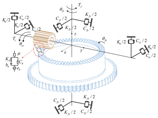
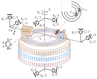
The face gear transmission system is composed of cylindrical gears and face gears meshing with each other. The meshing dynamics models under elastic support conditions are shown in Figs. 1 and 2. According to the parameters concentrated method, the cylindrical gear and face gear are regarded as the concentrated mass and concentrated inertia. The support axle is considered a massless rigid body, the bearings and the elastic supports are equivalent to the springs and the dampers. In the model, there were frictions between the stages of face gears, and dampers were added for the simulation. In the transmission process, there were normal dynamic meshing forces on the meshing teeth surface. According to the loading characteristics of face gears, the radial forces can be negligible. Similarly, the axial forces of the cylindrical gears are not working. Kcx and Kcz are the stiffness coefficients of the cylindrical gear in the x and z directions, respectively. Kfx and Kfy are the stiffness coefficients of the face gear in the x and z directions, respectively. Kh is the stiffness coefficient of the gear pair. Ccx and Ccy are the damping coefficients of the cylindrical gear in the x and z directions, respectively. Cfx and Cfy are the damping coefficients of the face gear in the x and y directions, respectively. Ch is the damping coefficient of the gear pair. eh is the static integrated transmission error of the gear pair. bh is the backlash of the gear pair. μ is the time-varying friction coefficient of the gear pair. θcy and θfz are the torsional angular displacements of cylindrical gear and face gear, respectively. Tc and Tf are the torques of cylindrical gear and face gear, respectively. Cf12 and Cf23 are the damping coefficients of friction and backlash between the stages of multistage face gears.
In the transmission process, there was a normal dynamic meshing force between the two tooth surfaces. There were circumferential force and radial force on the cylindrical gear, and the circumferential component force and the axial force were also generated on the face gears. Therefore, the coupled vibration model contains seven degrees of freedom:
Among these:
-
Bending vibration: The translations of cylindrical gear in x axis and z axis are xc and zc. The translation of face gear in x axis is xf.
-
Torsional pendulum vibration: The torsional pendulum of face gear in x axis is θfx.
-
Torsional vibration: The rotation of cylindrical gear in y axis is θcy. The rotation of face gear in z axis is θfz .
-
Axial vibration: The translation of face gear in z axis is zf.
When the unilateral constraint condition with impenetrable contact was introduced, the corresponding dynamic equation is:
In Eq. (2), M, C and K are the generalized mass matrix, generalized damped matrix, and generalized stiffness matrix, respectively. ς is the constraint equation, λ is the Lagrange multiplier, Q is the generalized force matrix, and F is the contact collision force.
2.2 Modeling of coupled vibration equations
According to the force analysis of the teeth, the normal dynamic meshing force Fn, and the component forces Fx and Fz along the coordinate axes x and z are:
In Eq. (3), km(t) is the time-varying meshing stiffness, f(dn) is the backlash function, cm is the meshing damping, and dn is the relative displacement in the normal direction.
The face gear is excited by vibration and error during the transmission process to generate relative displacement in the normal direction of the meshing points.
In Eq. (4), rcm and rfm are the meshing point radii of the cylindrical gear and face gear, respectively. αn are the normal pressure angles of meshing points. en(t) is the transmission error in the normal direction of the face gear.
Dynamic differential equations were established for each vibration direction of face gear transmission system:
In Eq. (5), Mc and Mf are the concentrated mass of cylindrical gear and face gear, respectively. kij and are the support stiffness and damping of the cylindrical gear or face gear along the x and z axes, respectively. Jcy is the rotational inertia of the cylindrical gear along the y axes. Jfx and Jfz are the rotational inertias of face gear in the x and z axes, respectively. Tc is the input torque acting on the cylindrical gear. Tf is the load torque acting on face gear. and are the damping and torsional pendulum vibration stiffness of face gear in the x axis, respectively. is the friction arm. rcb and rca are the base radius and addendum radius of the cylindrical gear, respectively. ε is the overlap ratio of the gear pair. scb is the base tooth pitch. nc is the speed of the cylindrical gear. is the direction function of the frictional force.
In order to reduce the vibrational degree of freedom in the system, it is necessary to simultaneous the torsional vibration equations:
After rewriting:
Hence,
The first and second derivative , of displacement dn in the normal direction of mesh points are introduced:
Equation (8) is substituted and rearranged as:
Me is substituted and rearranged as:
Let , , , be substituted and simplified as:
Then, the coupled vibration equation can be reduced to six degrees of freedom:
In the process of solving the differential equation of the gear coupling vibration, the torsional pendulum vibration has a little influence on the gear transmission system, so it can be neglected. The coupled vibration equation was reduced to five degrees of freedom. Equation (3) is introduced and rearranged as:
Due to the large magnitude of differences between the physical quantities, a numerical solution is extremely difficult, and it is also challenging to select the step size and control the error. Therefore, it is necessary to adopt the dimensionless normalization to the coupled vibration equation. Assuming that the natural frequency of the dynamic model of face gear pair is:
The dimensionless excitation frequency ND and the time independent variable τ are respectively defined as:
The results of the dimensionless transformation of the new 5 degrees of freedom coupled vibration equation are:
The static integrated transmission error equation is introduced and derivative is taken:
Let , , , ; , ; , , , ; , ; , , , .
Then, the dimensionless coupling vibration differential equation of the face gear can be expressed as:
The solution of the coupled vibration differential equation of face gear usually discretizes the time. A certain step length should be selected to obtain the relationship of acceleration, velocity, and displacement at every moment. Thereafter, integration is performed directly in steps to finally obtain both the transient and steady state solutions. When the effects of damping force, alternating excitation, and gear backlash are not considered, the integral initial values of steady state vibration can be obtained using the variable step length method. However, the face gear with double crown surface has a complex tooth surface structure, which is affected by the contact characteristics of the crown structure and the gear backlash. The meshing stiffness of the point contact is time-varying, wherein, it is difficult to carry out the complete numerical analysis. Therefore, the vibration of the face gear has strong nonlinear characteristics. Even if the linear model can well approximate the vibration response of the real system, it can only be used as a simplified model that reflects the real system. It is demanding to maintain the stability and reliability under the influence of various nonlinear errors, and its vibration characteristics are also difficult to predict.
A reduced order processing for differential equations was performed by introducing the state variable λ(τ), as a result, the Eq. (19) can be transformed into 10 first-order differential equations.
which are:
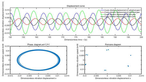
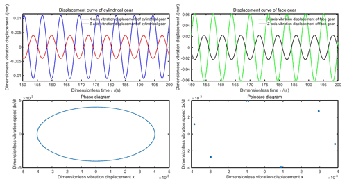
Neglecting the time-variation of the meshing stiffness, setting as average meshing stiffness and setting the meshing backlash to 0 mm, hence, the dimensionless coupled vibration equation can be defined as a linear differential equation. The linear characteristics of face gear were analyzed by the 4–5-order Runge–Kutta algorithm, which is the ODE45 variable step integral method in MATLAB. The main structural parameters of the gears are: tooth numbers Zc=17, . Modulus m=2 mm. Pressure Angle αn=20∘. Input torque Tc=100 N m. The dimensionless parameters of the vibration differential equation are assumed as: , Adc=0.093, , , Bdc=0.5509, , , Bdf=0.0231, Bde=0.8806, Ade=0.0149, , and . At the same time, the friction coefficient is defined as 0 and the load is 0. Under these conditions, the phase diagram and Poincare section were introduced to analyze the linear dynamic characteristics, as shown in Fig. 3.
Under the condition of without load, the time-history response of the system was a simple harmonic motion. The vibration displacement of the cylindrical gear was large at startup, and tended to be stable after a certain period of time. The face gear also presented a relatively stable period simple harmonic. The phase diagram is a plurality of closed elliptic curves that is expressed as a period response. The Poincare diagram is a number of discrete points.
4.1 Influence of variable speed stage number on the linear dynamics characteristics of the system
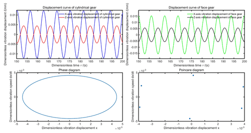
Other parameters were unchanged, the teeth number of the face gear were switched to the 1st, 2nd or 3rd stage, respectively, the corresponding equivalent mass, rotational inertia and gear ratio change accordingly. The displacement curves, phase diagrams, and Poincare diagrams of the linear dynamics are shown in Figs. 4, 5, and 6.
As per Figs. 4, 5, and 6, under the conditions without external excitation, the phase diagrams of face gears in all the stages were closed curves, which indicate that all the stages had stable vibration period characteristics. After inputting torque and speed, the system reached a stable state in an extremely short time-history, and its vibration displacement was also weak, which indicates that the multistage face gears system can achieve stable meshing transmission.
4.2 Influence of friction coefficient on linear dynamic characteristics of the system
Taking the 2nd face gear pair as the object, the other parameters remained unchanged, while the friction coefficients were set to 0.1, 0.5, and 1, respectively. Inspite of free idling of the other two stages face gears, there was still friction damping. It was necessary to define additional friction coefficients in the 1st stage and 3rd stage to be 0.01, and the 2nd stage to be 0.02. The displacement curves, phase diagrams, and Poincare diagrams of the linear dynamics are shown in Figs. 7, 8, and 9.
As per Figs. 7, 8, and 9, the elastic deformation was generated in gears during the meshing process, which led to the collision of the newly meshed gear teeth, thus, generating the pulse power. The meshing frequency includes not only the fundamental frequency vibration but also high harmonic vibration. The friction between two meshing teeth would also induce self-excited vibration under certain conditions. The meshing process is a comprehensive transient excitation, which causes the gear to attenuate free vibration. As the friction coefficient becomes larger, the vibration displacement increasingly deviates from the meshing trajectory. When the friction coefficient was less than 0.1, the vibration characteristics changed from single cycle to double cycle, and then, to quasi-periodic cycle. When the same was greater than 0.1, the vibration displacements in the x and z directions were gradually towards the same direction under the influence of friction damping. The Poincare diagram is presented as a complex set of points. Therefore, reasonable gear materials and appropriate tooth surface processing technology should be used to enhance the surface quality and reduce the tooth surface friction.
4.3 Influence of integrated meshing stiffness on linear dynamic characteristics of the system
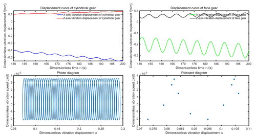
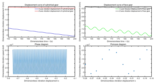
Taking the 2nd face gear pair as the object, other parameters remained unchanged. The friction coefficient was set to 0.01, when the input torque is set to 100, 500, and 1000 N m−1 respectively. The integrated meshing stiffness of the corresponding face gears pairs were 9.852×10⁷ N m−1, 5.7617×10⁷ N m−1, and 4.5731×10⁷ N m−1. The displacement curves, phase diagrams, and Poincare diagrams of the linear dynamics are shown in Figs. 10, 11 and 12.
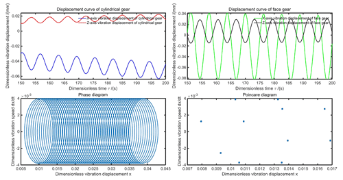
Figure 10Displacement, phase, and Poincare diagrams of comprehensive meshing stiffness 9.852×7 N m−1.
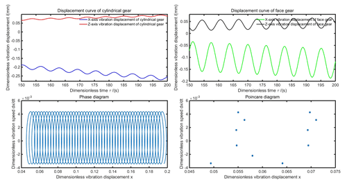
Figure 11Displacement, phase, and Poincare diagrams of comprehensive meshing stiffness 5.7617×10⁷ N m−1.
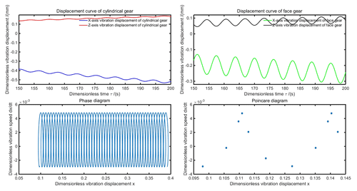
Figure 12Displacement, phase, and Poincare diagrams of comprehensive meshing stiffness 4.5731×10⁷ N m−1.
The integrated meshing stiffness is directly related to the input torque and the load deformation. As per Figs. 10, 11 and 12, the vibration displacement amplitude increased with the reduction of the integrated meshing stiffness. Owing to the frictional damping, the degree of vibration displacement increasingly deviated from the meshing trajectory. The phase diagram is multiple spiral curves that is expressed as a quasi-periodic response, while the Poincare diagram is a number of irregular discrete points.
4.4 Influence of loading speed on linear dynamic characteristics of the system
Taking the 2nd face gear pair as the object, the friction coefficient was 0.01, when the input torque was 100 N m−1, other parameters remained unchanged, the loading speed was set to 300, 500, 1000, and 3000 r min−1, respectively, and the corresponding meshing angle frequency changed accordingly.
After inputting speed excitation, the linear system generated periodic oscillations, which then decayed to a stable vibration state. Larger the input speed, longer was the oscillation period, and larger was the vibration displacement amplitude. The phase diagram presents stable multiple spiral curves after oscillation, whose stability history can be considered as a quasi-periodic response. The Poincare diagram is a number of discrete points, which are concentrated to turnaround in a trajectory area when the speed was 300 r min−1.
4.5 Influence of excitation frequency on linear dynamic characteristics of the system
Taking the 2nd face gear pair as the object, the friction coefficient was 0.01, the input torque was 100 N m−1, the loading speed was 300 r min−1, while the other parameters remained unchanged. The dimensionless excitation frequencies were extracted with 0.1648, 0.0699, 0.0537, 0.0492, 0.0453, and 0.0438 Hz, respectively. The corresponding first six order natural frequencies were 3239.9, 7644.8, 9943.5, 10 852, 11 800, and 12 193 Hz. The displacement curves, phase diagram, and Poincare diagram of the linear dynamic with dimensionless excitation frequencies 0.1648 is shown in Fig. 13 (limited to space, others are not listed).
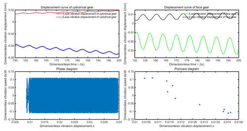
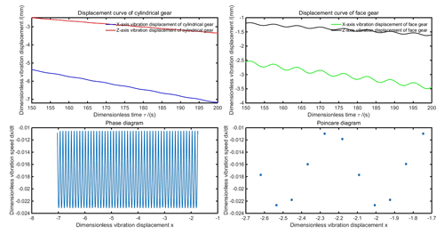
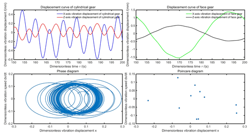
Figure 13Displacement, phase and Poincare diagrams of linear system with excitation frequency 0.1648 Hz.
As per Fig. 13, the dimensionless excitation frequency is related to the angular velocity frequency. Similarly, for different frequencies' diagrams, under the condition of inputting a certain speed, as the excitation frequency decreased, the vibration attenuation period of the linear system became longer. The vibration period also became longer after meshing stability, but the vibration displacement amplitude did not change significantly. The phase diagram present stable multiple spiral curves after oscillation, while the Poincare diagram is a number of irregular discrete points.
The linear model can well approximate the real system dynamics behavior in normal conditions, but overall, it is a simplified model, wherein, it is difficult to obtain a stable and reliable linear approximation (Atanasovska, 2017; Zajicek and Dupal, 2017). Especially, in the analysis of long time-history, the extremely weak nonlinear factors that simplify or even ignore often lead to some unpredictable errors. In general, the simple harmonic motion of the nonlinear system still contains multiple frequency vibration phenomenon with periodicity (or multiple periodicity), but it does not necessarily have the same frequency with the simple harmonic excitation. Under certain excitations, there are several kinds of steady-state vibration characteristics, which make the prediction of the nonlinear dynamic response extremely difficult. Therefore, it is necessary to study the nonlinear dynamics of face gear transmission system, to explore the effect of the main nonlinear factors, in order to reveal the complete dynamic behavior as much as possible. For the multistage face gears transmission system, the teeth surface morphology was reconstructed (or modified) with double crown structure, there were inevitable machining and assembly errors that resulted in a randomly changing gear backlash during the meshing process. Moreover, the double crown tooth surface was difficult for machining, and the frictional response of each tooth surface may cause a certain degree of aperiodic mutation because of the jumping and wear of teeth in the meshing contact area. And it is coupled with time-varying meshing stiffness, damping and external excitation to form a gear dynamics with strong nonlinear characteristics. In this section, the influence of nonlinear dynamic characteristics would be analyzed through the characterization factors such as variable speed stages, friction coefficient, transmission error, excitation frequency, and time-varying stiffness.
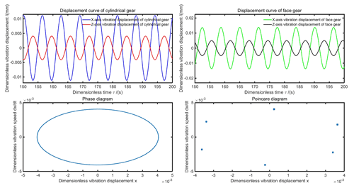
With the factors such as the time-variation of the meshing stiffness, the elastic deformation characteristics of the dynamic points contact, the gear backlash, the damping force, the alternating excitation, and the frictional characteristics of the tooth surface, the dimensionless coupled vibration equations can be defined as nonlinear differential equations. Assuming that the dimensionless parameters of the vibration differential equation are: , Adc=0.093, , , Bdc=0.5509, , , Bdf=0.0231, Bde=0.8806, Ade=0.0149, , and . Using the 4–5-order Runge–Kutta method, with the friction coefficient as 0.02 and the load as 50 N m−1, the nonlinear characteristics of face gears were analyzed, as shown in Fig. 14.
From Fig. 14, under certain load conditions, the response of system is a simple harmonic motion with oscillations in the initial period of the time-history. The vibration displacement of the cylindrical gear was large at startup, and tended to be stable after a period of time. The face gear also presented a relatively stable period simple harmonic. The phase diagram is a plurality of intertwined curves but not crossed, not repeated, and not closed, which is expressed as a quasi-period response. The Poincare diagram is a number of discrete points.
5.1 Influence of variable stage numbers on the nonlinear dynamic characteristics of the system
Other parameters remained unchanged, the teeth number of the face gear was switched to the 1st, 2nd, or 3rd stage, respectively, while the corresponding equivalent mass, rotational inertia, and gear ratio were changed accordingly. The displacement curves, phase diagrams, and Poincare diagrams of the nonlinear dynamics are shown in Figs. 15, 16 and 17.
As per Figs. 15, 16, and 17, under the conditions without external excitation, the vibration displacement period of the face gears in all the stages decreased with the increase in the transmission ratio. Because of the gear backlash, the vibration displacement amplitudes of the cylindrical gears generated a certain degree of jumping. The phase diagrams of the nonlinear system is a plurality of intertwined curves but not crossed, not repeated, and not closed, which indicates that there are relatively stable quasi-period characteristics.
5.2 Influence of friction coefficient on the nonlinear dynamic characteristics of the system
Taking 2nd face gear pair as the object, other parameters remained unchanged, the friction coefficient was set to 0.5, 1 and 2 respectively. Because of free idling of the other two stages face gears, but there were still friction damping. Hence, it was necessary to define additional friction coefficients in 1st stage and 3rd stage face gears to be 0.01, and the 2nd stage to be 0.02. The displacement curve, phase diagram, and Poincare diagram of the nonlinear dynamics with friction coefficient 0.5 are shown in Fig. 18 (limited to space, others are not listed).
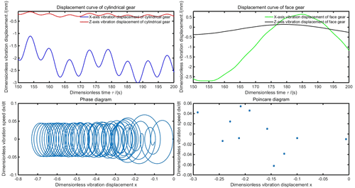
Figure 18Displacement, phase, and Poincare diagrams of nonlinear system with friction coefficient 0.5.
From Fig. 18, in the nonlinear system, the friction between the two meshing teeth can induce self-excited vibrations under certain conditions, and because of the gear backlash and frictional damping, the gears generated attenuation free vibration accompanied with contact impact. Similarly, as the friction coefficient became larger, the vibration displacement increasingly deviates from the meshing trajectory. The trend is basically consistent with the linear systems, when the friction coefficient was less than 0.1, the vibration characteristics changed from single cycle to double cycle, and then to quasi-periodic cycle. When greater than 0.1, the vibration displacements in the x and z directions were gradually towards the same direction under the influence of friction damping. The phase diagram is a non-closed curve with multiple spirals. The Poincare diagram is presented as an irregular set of points.
5.3 Influence of transmission error on nonlinear dynamic characteristics of the system
Taking 2nd face gear pair as the object, the friction coefficient was 0.01, the input torque was 100 N m−1, the loading speed was 300 r min−1, while the other parameters remained unchanged. The transmission error fluctuation values were extracted as 0, 0.1, 0.25, and 0.5, respectively. The displacement curve, phase diagram, and Poincare diagram of the nonlinear dynamics with transmission error 0.1 is shown in Fig. 19 (limited to space, others are not listed).
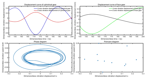
Figure 19Displacement, phase, and Poincare diagrams of nonlinear system with transmission error fluctuation value 0.1.
As per Fig. 19, when the transmission error was 0.1, the nonlinear system has significant periodic attenuation harmonic motion. The phase diagram is a non-closed spiral curve, and the Poincare diagram is a number of discrete points set concentrating in four regions. Similarly, as the transmission error increased, the vibration displacement generated different degrees of jumping during the simple harmonic motion, whose amplitude also increases accordingly. The phase diagram is a plurality of intertwined and crossed curves combination but neither repeated nor closed. The Poincare diagram mush appears as a number of irregular discrete points.
5.4 Influence of excitation frequency on nonlinear dynamic characteristics of the system
Taking 2nd face gear pair as the object, the friction coefficient was 0.01, the input torque was 100 N m−1, the transmission error fluctuation value was 0.18, while the other parameters remained unchanged. The dimensionless excitation frequency was extracted as 0.1648, 0.2747, 0.5495, and 1.6484 Hz, respectively. The displacement curves, phase diagrams, and Poincare diagrams of the nonlinear dynamics are shown in Figs. 20, 21, 22 and 23.
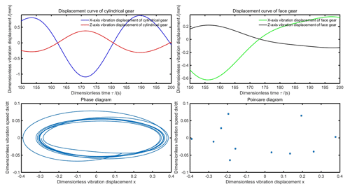
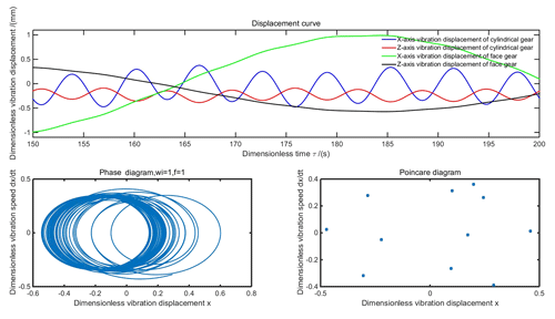
Figure 20Displacement, phase, and Poincare diagrams of nonlinear system with excitation frequency 0.1648.
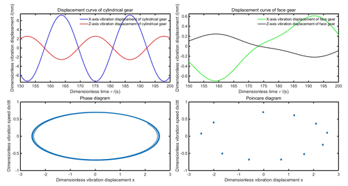
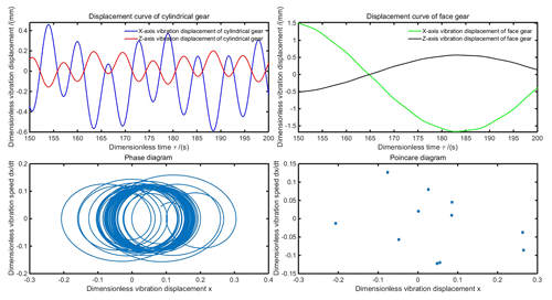
Figure 21Displacement, phase, and Poincare diagrams of nonlinear system with excitation frequency 0.2747.
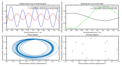
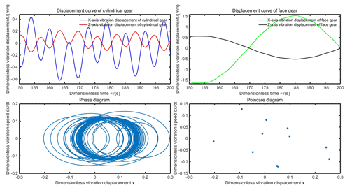
Figure 22Displacement, phase, and Poincare diagrams of nonlinear system with excitation frequency 0.5495.
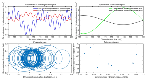
Figure 23Displacement, phase, and Poincare diagrams of nonlinear system with excitation frequency 1.6484.
As per Figs. 20, 21, 22 and 23, when the excitation frequency was small, for instance 0.1648, the vibration displacement was a periodic non-harmonic response, which is accompanied with the oscillation attenuation process in the initial period of time-history. When the excitation frequency was 0.2747, the vibration displacement of cylindrical gear reached a stable periodic harmonic response, but face gear still presented a periodic non-harmonic response. The phase diagram is a plurality of non-closed elliptic curves that can be expressed as a quasi-periodic vibration. The Poincare diagram forms a circular area with distinct identification. When the excitation frequency was 0.5495, the vibration displacement of the cylindrical gear presented periodic fluctuation characteristic after oscillation attenuation, and the face gear also tended to harmonic vibration. The phase diagram is a heart-shaped curve region formed by a plurality of non-circular and non-closed curves, which can be expressed as a quasi-periodic vibration response characteristic. The Poincare diagram is a number of discrete points that gradually diverged. When the excitation frequency was 1.6484, the vibration displacements of cylindrical gear and face gear were both the periodic harmonic response, and the phase diagram is a non-circular closed curves set similarly in shape as a curl. The Poincare diagram is a set of irregular discrete points.
In this study, single/multistage coupled vibration models were established to derive the coupled vibrations equations. The phonetic relationships of the key parameters such as equivalent mass, rotational inertia, equivalent mesh stiffness, support stiffness, and meshing damping coefficient to dynamic characteristics were studied. The influence rules of the factors such as integrated transmission error, dynamic load, tooth surface friction, loading speed, and load on the transmission system were analyzed. Thus, the linear and nonlinear dynamic characteristics of the coupled vibration differential equations were revealed.
-
The single/multistage coupled vibration models were established using the parameters concentrated method. 7 degrees of freedom vibration equations such as bending vibration, torsional vibration, torsional vibration, and axial vibration were established according to the meshing relationship. The primary characterization parameters such as equivalent mass, integrated meshing stiffness, support stiffness and equivalent damping were defined and described. At the same time, the conditions and the main inducing factors of internal excitation or external excitation of the transmission system were also clarified. Thus, a dynamic model suitable for the multistage face gears transmission has been established and optimized.
-
The vibration equation was processed by reducing the degrees of freedom, and the corresponding parameters were subjected to dimensionless normalization. The ODE45 integral method was introduced to solve the vibration equations. The linear and nonlinear vibration conditions were defined, and the effects of various parameters or excitations of the linear or nonlinear system were analyzed in detail to accurately solve the vibration performance and power transmission performance of the transmission system.
-
The linear dynamic characteristics can approximate the vibration response of the real system, but it can only be expressed as a simplified model. It is difficult to maintain the stability and reliability under the influence of various nonlinear errors, and its vibration characteristics are also difficult to predict. Therefore, the accuracy of the analysis results for the dynamic characteristics of the transmission system can be improved by comprehensively synthesizing the interaction of nonlinear factors such as external excitation and internal excitation.
No data sets were used in this article.
XC developed the overall concept of the paper, conducted the numerical analyses and wrote the majority of the paper. QH supervised the process and contributed in structuring the research, reviewing the results and reviewing the paper. ZX assisted in the experimental design and verified the suggested model. CZ checked the writing language.
The authors declare that they have no conflict of interest.
The authors would like to thank Xiaofeng Liang and Yao Ding for free help in English professional writing. This work was supported by the National Natural Science Foundation of China under Grant No. 51575191, and Guangdong Provincial Enterprises Key Laboratory Foundation about Mid-High-end Industrial Robot Technology under Grant No. 2018B030323027.
This research has been supported by the National Natural Science Foundation of China (grant no. 51575191) and the Guangdong Provincial Enterprises Key Laboratory Foundation about Mid-High-end Industrial Robot Technology (grant no. 2018B030323027).
This paper was edited by Guimin Chen and reviewed by Luca Bruzzone and one anonymous referee.
Atanasovska, I.: Multi-body contact in non-linear dynamics of real mechanical systems, X International Conference on Structural Dynamics (Eurodyn 2017), 199, 510–515, 2017.
Atanasovska, I. and Hedrih, K.: A New Collision Model for Analysing the Vibro-Impact of Spur Gears, T. Famena, 42, 1–13, 2018.
Bouslema, M., Frikha, A., Abdennadhar, M., Fakhfakh, T., Nasri, R., and Haddar, M.: Effects of modal truncation and condensation methods on the Frequency Response Function of a stage reducer connected by rigid coupling to a planetary gear system, Cr. Mecanique, 345, 807–823, 2017.
Cai, Z. Q. and Lin, C.: Dynamic Model and Analysis of Nonlinear Vibration Characteristic of a Curve-Face Gear Drive, Stroj. Vestn.-J. Mech. E, 63, 161–170, 2017.
Chowdhury, S. and Yedavalli, R. K.: Dynamics of low speed geared shaft systems mounted on rigid bearings, Mech. Mach. Theory, 112, 123–144, 2017.
Dadon, I., Koren, N., Klein, R., and Bortman, J.: A Step Toward Fault Type and Severity Characterization in Spur Gears, J, Mech, Design, 141, 8–30, 2019.
Dong, H. and Hu, Y. H.: Dynamic Load-Sharing Characteristic Analysis of Face Gear Power-Split Gear System Based on Tooth Contact Characteristics, Aip Conf. Proc., 1955, 030028-1–030028-5, 2018.
Fernandez-Del-Rincon, A., Garcia, P., Diez-Ibarbia, A., De-Juan, A., Iglesias, M., and Viadero, F.: Enhanced model of gear transmission dynamics for condition monitoring applications: Effects of torque, friction and bearing clearance, Mech. Syst. Signal Pr., 85, 445–467, 2017.
Hmida, A., Hammami, A., Chaari, F., Khabou, M. T., and Haddar, M.: Modal Analysis of Spur Gearbox with an Elastic Coupling, Advances in Acoustics and Vibration, 5, 153–163, 2017.
Hu, Z. H., Tang, J. Y., Chen, S. Y., and Sheng, Z. H.: Coupled translation-rotation vibration and dynamic analysis of face geared rotor system, J. Sound Vib., 351, 282–298, 2015.
Lin, C., Liu, Y., and Gu, S. J.: Analysis of nonlinear twisting vibration characteristics of orthogonal curve-face gear drive, J. Braz. Soc. Mech. Sci., 37, 1499–1505, 2015.
Liu, B., Zhao, J. G., Qian, J. H., and Wang, X. Y.: Nonlinear Vibration Analysis of Helical Face-Gear Transmission System with Multi-Factor, 2016 3rd International Conference on Mechanics and Mechatronics Research (Icmmr 2016), 77, 07010-16, 2016.
Liu, D. W., Gu, D. D., and Liu, Z. J.: Coupled vibration modeling and dynamic characteristics of noncircular face gear drive system with time-varying instantaneous center excitation, P. I. Mech. Eng. C-J. Mec., 233, 4947–4959, 2019.
Peng, M. and DeSmidt, H. A.: Torsional Stability of a Face-Gear Drive System, J. Am. Helicopter Soc., 60, 1–11, 2015.
Ren, F., Luo, G. F., Shi, G. Q., Wu, X. L., and Wang, N.: Influence of manufacturing errors on dynamic floating characteristics for herringbone planetary gears, Nonlinear Dynam., 93, 361–372, 2018.
Sakaridis, E., Spitas, V., and Spitas, C.: Non-linear modeling of gear drive dynamics incorporating intermittent tooth contact analysis and tooth eigenvibrations, Mech. Mach. Theory, 136, 307–333, 2019.
Saxena, A., Chouksey, M., and Parey, A.: Measurement of FRFs of coupled geared rotor system and the development of an accurate finite element model, Mech. Mach. Theory., 123, 66–75, 2018.
Tatar, A., Schwingshackl, C. W., and Friswell, M. I.: Dynamic behaviour of three-dimensional planetary geared rotor systems, Mech. Mach. Theory, 134, 39–56, 2019.
Wu, C. B., Cheng, J. H., and Zhang, G.: Study on Nonlinear Vibration of Planetary Gear System with NN – type Small Tooth Difference, 2017 32nd Youth Academic Annual Conference of Chinese Association of Automation (Yac), 2017, 645–649, 2017.
Xiao, Z. M., Wu, X., and Chen, Q.: Dynamic Modeling and Analysis of Multi-Stage Planetary Gears Coupled with Central Bearings and Housing, T. Can. Soc. Mech. Eng., 40, 1007–1018, 2016.
Yu, W. and Mechefske, C. K.: A New Model for the Single Mesh Stiffness Calculation of Helical Gears Using the Slicing Principle, Ijst-T. Mech. Eng., 43, 503–515, 2019.
Zajicek, M. and Dupal, J.: Analytical solution of spur gear mesh using linear model, Mech. Mach. Theory, 118, 154–167, 2017.
Zhang, A. Q., Wei, J., Qin, D. T., and Hou, S. S.: Analytical coupling characterization of multi-stage planetary gear free vibration considering flexible structure, J. Vibroeng., 19, 3994–4008, 2017.
Zhang, L., Wang, Y., Wu, K., Sheng, R. Y., and Huang, Q. L.: Dynamic modeling and vibration characteristics of a two-stage closed-form planetary gear train, Mech. Mach. Theory, 97, 12–28, 2016.
Zhang, L. N., Wang, Y., Wu, K., Sheng, R. Y., and Huang, Q. L.: Modal properties of a multi-stage power-split planetary gear set, Adv. Mech. Eng., 9, 1–10, 2017, 2017.
- Abstract
- Introduction
- Establishment of multistage face gears coupled vibration model
- Solving of coupled vibration differential equation of face gear
- Analysis of linear dynamic characteristics of face gear
- Analysis of nonlinear dynamic characteristics of face gear
- Conclusion
- Data availability
- Author contributions
- Competing interests
- Acknowledgements
- Financial support
- Review statement
- References


