the Creative Commons Attribution 4.0 License.
the Creative Commons Attribution 4.0 License.
 | 26 Aug 2019
Failure analysis of a re-design knuckle using topology optimization
Yung-Chuan Chen
Hsing-Hui Huang
Chen-Wei Weng
In this study, a systematic design process is carried out for the design of the knuckle. A systematic method is proposed for the design and analysis of a lightweight steering knuckle in an electric vehicle. In the proposed approach, a finite element (FE) model of the knuckle is constructed based on an inspection of the suspension and steering requirements of the target vehicle and the results of a kinematic analysis. A two-stage topology optimization method is then applied to refine the material distribution within the FE model in such a way as to minimize the knuckle weight. Finally, FE simulations are performed to evaluate the strength of the knuckle under road impact conditions and to determine the fatigue life of the knuckle for four ISO 8608 road classes (A–D). The results show that the optimized knuckle has a weight of 3.64 kg (approximately 6.2 % lighter than the original knuckle of the same strength and material) and achieves fatigue lives of 2.512×10¹¹, 2.972×10⁸, 5.598×10³ and 2.432×101 cycles for road classes A, B, C and D, respectively.
- Article
(6994 KB) - Full-text XML
- BibTeX
- EndNote


The overall feeling that a vehicle brings to its drivers and passengers is governed mainly by the design of the chassis. The knuckle, which connects the wheel to the steering and suspension systems, is one of the most important parts of the chassis and has a critical effect on the handling and steering characteristics of the vehicle. Modern vehicles rely on the use of lightweight designs to improve the energy efficiency. Moreover, to improve the handling, it is essential to minimize the unsprung mass. Thus, the problem of minimizing the weight of the knuckle component, thereby reducing the load imposed on the suspension system, has attracted significant attention in the automotive industry in recent decades.
Among the various methods available for achieving weight reduction in the design process, optimization methods provide a particularly attractive approach. Song and Lee (2011) employed a reliability-based design optimization technique based on the moving least squares method (MLSM) to minimize the weight of a knuckle component under bump and brake loading conditions subject to given stress, deformation and frequency constraints. Muhamad et al. (2012) combined a shape optimization technique with HyperWorks simulations to reduce the mass of the knuckle component in a passenger vehicle. The results showed that the optimized structure was around 8.4 % lighter than the original design. Shelar and Khairnar (2014) optimized the design of a steering knuckle using a design of experiments (DOE) approach based on various key design parameters, including the flange and hub thickness. The redesigned knuckle was shown to be around 9 % lighter than the original component. Bhardwaj et al. (2018) performed ANSYS simulations to minimize the weight of a steering knuckle subject to strength and stiffness constraints and three different material selections (Al7075-T6, Al6061-T6 and AISI 1045). Fan et al. (2011) analyzed the strength of a steering knuckle component under three harsh driving conditions. Sivananth and Vijayarangan (2015) employed a multibody dynamics approach to perform knuckle strength analyses under three different driving states. In general, the results showed that the main failure mode of the knuckle was one of fatigue. Wang et al. (2002) performed multibody dynamics simulations to investigate the strength of the knuckle component in a MacPherson suspension system under three different driving conditions. In the studies described above, the knuckle strength was evaluated under static loads only. However, under real-world driving conditions, the knuckle load varies dynamically as the wheel travels over the road surface and the vehicle performs braking, accelerating, and turning maneuvers. Therefore, when designing and analyzing a knuckle, it is necessary to consider not only the static load acting on the knuckle, but also the fatigue strength of the knuckle under the effects of long-term cyclic load. Zoroufi and Fatemi (2004) contended that fatigue is the main factor determining the service life of a knuckle and thus serves as a useful indicator for evaluating the performance of competing manufacturing processes and materials. Vijayarangan et al. (2013) investigated the optimal design of a knuckle fabricated of metal matrix composite (MMC) and found that the area of the knuckle connected to the shock absorber was particularly prone to fatigue damage.
The literature contains many studies on the use of numerical modeling techniques to reduce the weight of the knuckle component or investigate its fatigue behavior. Accordingly, the present study proposes a framework based on topology optimization and finite element analysis (FEA) simulations for minimizing the weight of the knuckle component in a real-world five-seat electric vehicle (EV) under the prescribed design space, load and boundary conditions, and then evaluating the strength and fatigue life of the knuckle under various road class conditions.
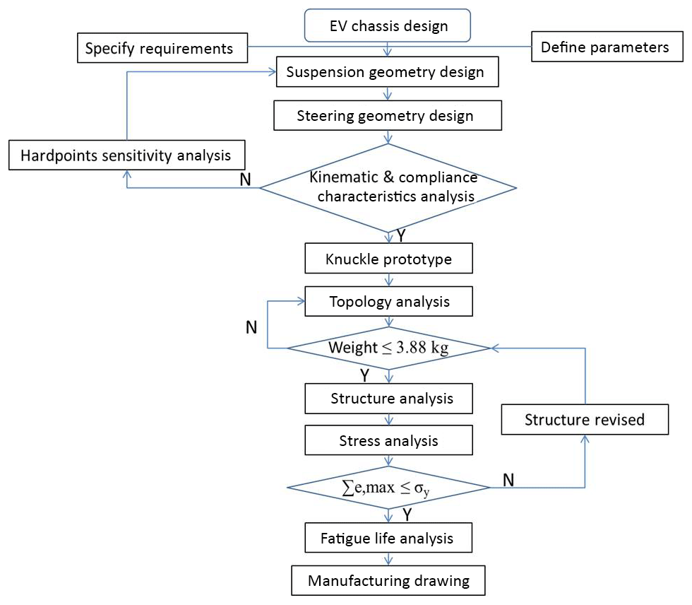
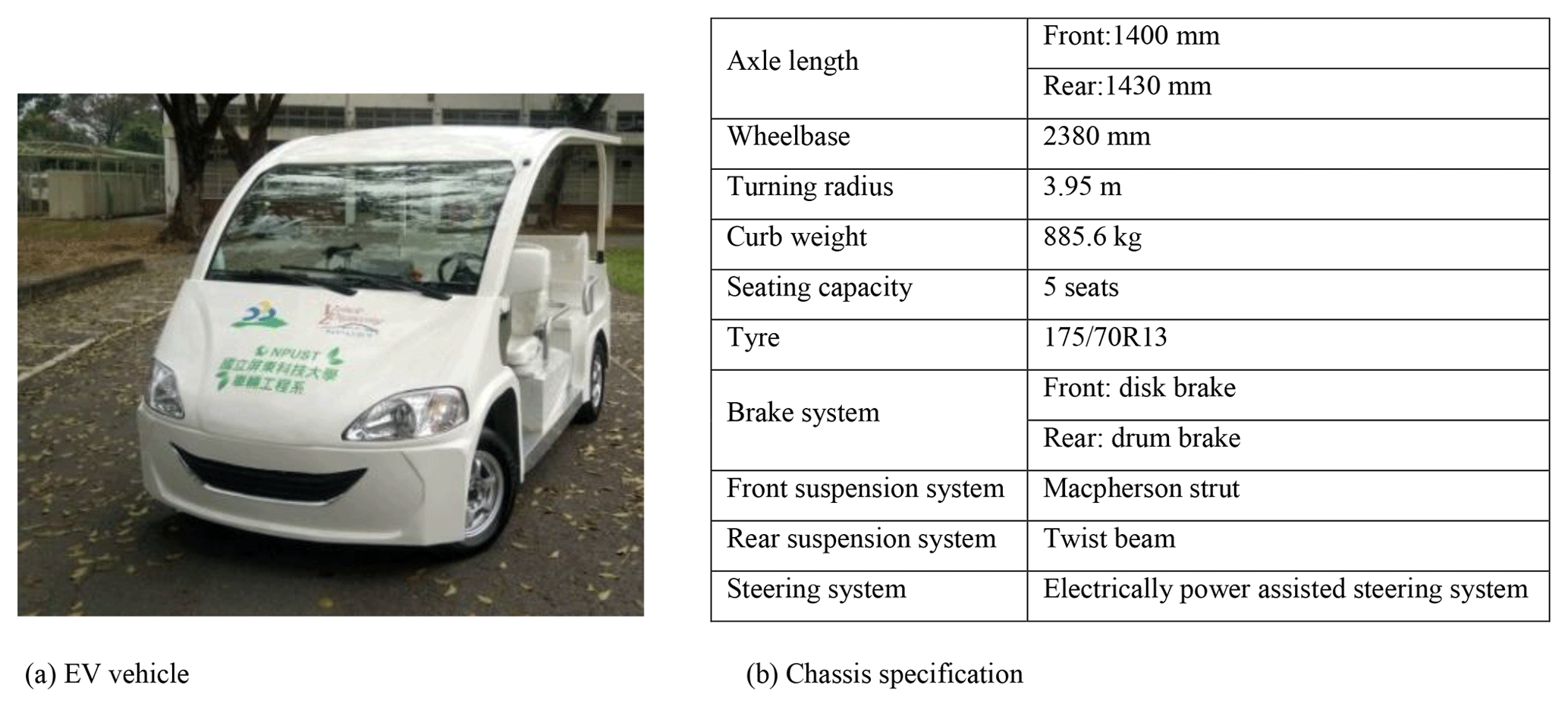
Figure 1 shows the main steps in the methodology proposed in this study for the lightweight design and analysis of the knuckle. Figure 2a and b show a photograph of the target vehicle and the vehicle specification, respectively. As shown in Fig. 1, the design process commences by establishing the geometry designs of the suspension and steering systems of the target EV. Having conducted a kinematic and hardpoints sensitivity analysis, TOSCA simulations are performed using an ABAQUS finite element (FE) model to optimize the material layout of the prototype knuckle design. Once the weight of the knuckle has been reduced to a value less than that of the original knuckle (3.88 kg), further simulations are performed to analyze the strength of the designed knuckle. If the strength fails to meet the prescribed requirement, the structure of the knuckle is modified accordingly. Finally, FE-Safe analyses are performed to evaluate the fatigue strength of the knuckle under various road roughness conditions.
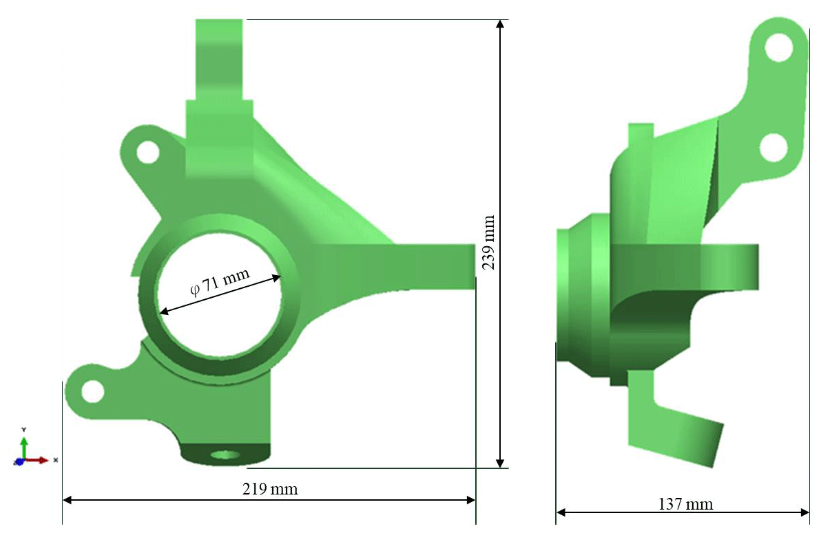
Based on an analysis of the suspension and steering characteristics of the target vehicle, the physical constraints for the topology optimization process were set as follows: (1) an inclination angle must conform to the analysis result of 13.2∘; (2) the hardpoint thickness for a shock absorber of 26 mm; (3) the hardpoints spacing between the two strut mount points of 53 mm; (4) a brake caliper hardpoints spacing of 131 mm; and (5) a wheel bearing inner diameter of 71 mm. Furthermore, the overall dimensions of the knuckle were set as 219 mm (length), 137 mm (width) and 239 mm (height) (see Fig. 3).
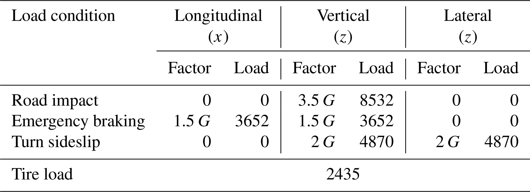
Given the constraints above, the aim of the topology optimization process is to find the optimal material distribution within the specific design space for the specified loading conditions. In performing the optimization process, it was assumed that the knuckle was fabricated of GCD450 material. Furthermore, to avoid affecting the strength of the hardpoints for the caliper, tie rod and lower control arm, the optimization process was confined only to certain regions of the model, as shown in Fig. 4. The topology optimization analysis process considered three static loading conditions, namely road impact, emergency braking, and turn sideslip. For each condition, a force was applied to the upper seat of the shock absorber in an upward direction as a single wheel load weight and specific load conditions relating to the particular static condition were then added to the center of the wheel bearing (see Table 1).
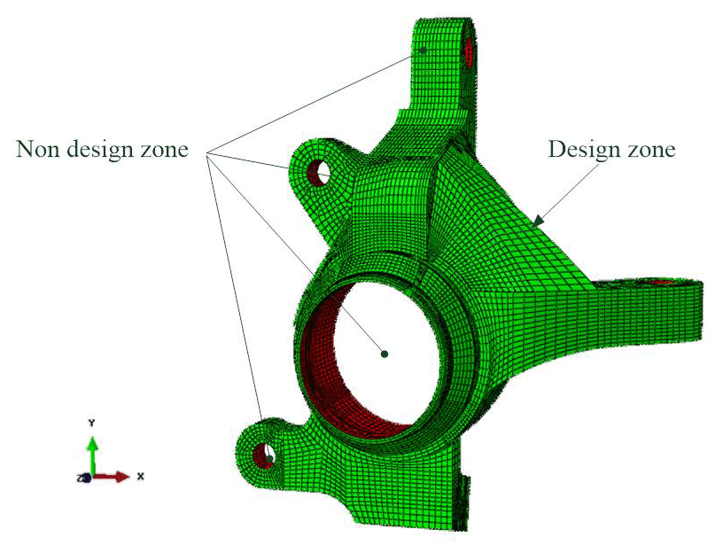
Table 1Vehicle load factor and specific load conditions (Fan et al., 2011). Unit: Newton.
Although the study considered three static load conditions, the remainder of this paper focuses on the road impact load condition for reasons of conciseness. As shown in Fig. 5, in optimizing the structure of the knuckle for the road impact condition, physical constraints were applied in the x, y and z directions at the shock absorber hardpoints (A and B), tie rod hardpoint (C), and lower control arm hardpoint (E), and a load of 8532 N was applied in the upward y direction to the wheel center (D). The aim of the optimization process was to minimize the weight of the knuckle using the stress (σy) as the constraint function.
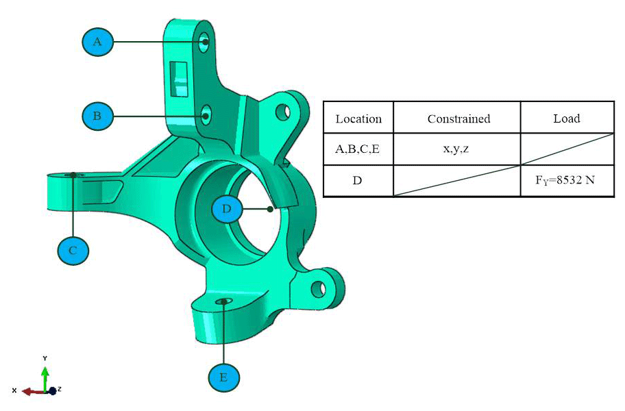
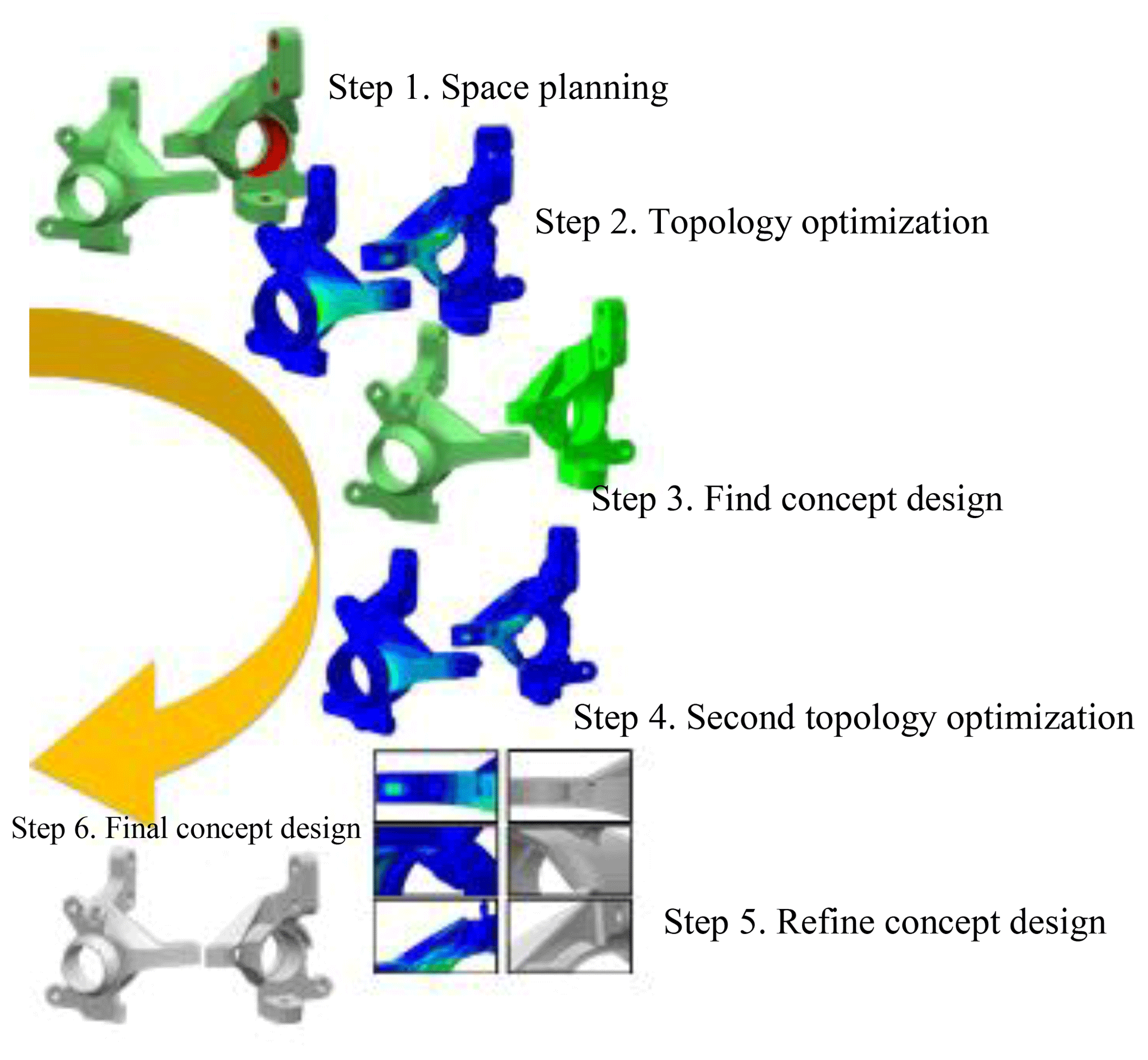
Figure 6 shows the basic steps in the topology optimization process. As shown, topology optimization was performed twice. The aim of the first optimization process was to determine an initial concept design for the lightweight knuckle, while the aim of the second optimization process was to refine the design. The final design was found to have a weight of 3.64 kg, and was thus about 6.2 % lighter than the original design (3.88 kg). In addition, the knuckle arm connecting rib thickness was Ta=5 mm and the shock absorber rib thickness was Tr=6.5 mm.
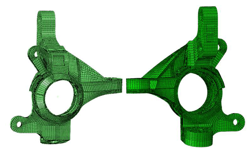
Strength and fatigues analyses of the redesigned knuckle were conducted using static and dynamic three-dimensional (3-D) elasto-plastic finite element (FE) models, respectively (see Fig. 7). In both cases, the model was meshed using 3-D hexahedron eight-node elements.
In performing the fatigue life analysis of the knuckle, the suspension system was simplified as a 3-D two-node beam element model with spring (K) and damping (C) parameters (see Fig. 8). In addition, a load displacement signal was input to the FE model through the hardpoints of the knuckle support arm to simulate the total load of the vehicle (including the weights of the driver, passenger, power system and battery system, respectively).
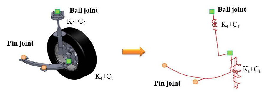
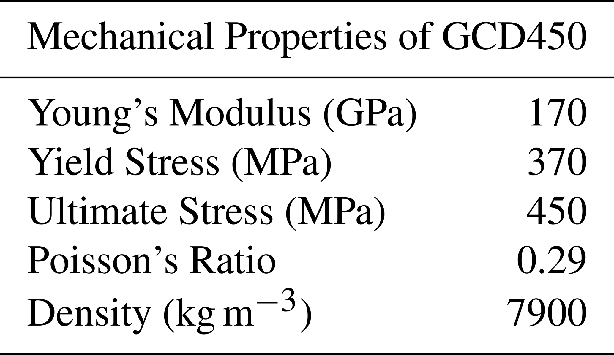
Table 2 shows the material properties of the knuckle used in the FE simulations. As described above, the impact load was input to the wheel center of the model and the simulation process then calculated the x, y and z direction forces at the hardpoints of the knuckle using a quarter vehicle suspension model.
Table 2Material properties of knuckle used in finite element simulations.
4.1 Boundary conditions for strength analysis
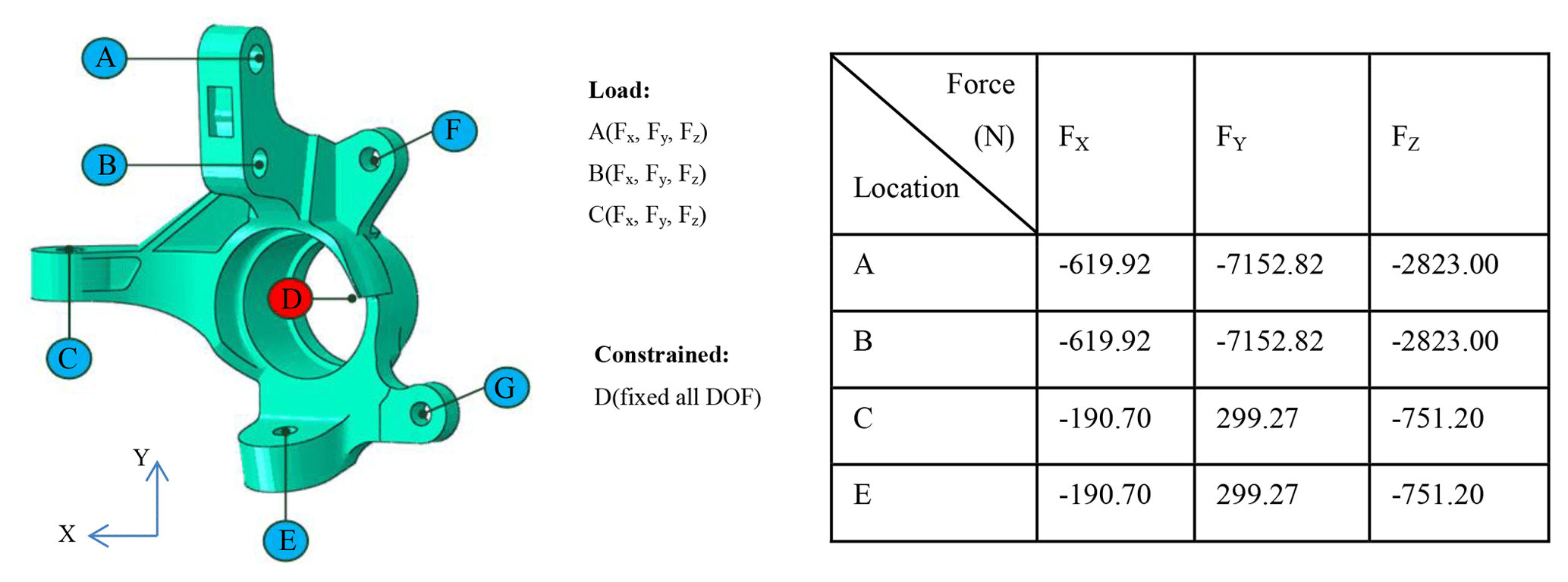
In evaluating the strength of the knuckle under impact loads, the aim of the FE simulations was to determine the displacement of the wheel when the vehicle passed over a large bump, thereby imposing a large stress on the related components of the suspension system. Accordingly, the degrees of freedom of the FE model were constrained in all six directions at D (the center of the wheel axis), and the forces shown in Fig. 9 were applied in the x, y and z directions at points A and B (suspension strut hardpoints), C (tie rod hardpoint), and E (lower control arm hardpoint). In addition, a load of 8532 N was applied at the center of the wheel (see Table 1).
4.2 Boundary conditions for fatigue life analysis
To perform the fatigue life analysis of the knuckle, the load displacement signal of the knuckle strut was obtained using the quarter vehicle suspension system model shown in Fig. 10 consisting of a shock absorber, knuckle, hub, ball joint, bearing, lower control arm, and tie rod. The stiffnesses of the front suspension spring and tire were set as Kf=60 N mm−1 and Kt=310 N mm−1, respectively, while the damping coefficients were set as 0.912 and 0.0031 N s mm−1, respectively. In calculating the service life of the knuckle under different road roughness conditions (i.e., different ISO road classes), two input signals were considered, namely a y direction displacement signal at the shock absorber hardpoints (A and B in Fig. 10) and the displacement signal of the road surface at the tire position (see Fig. 11).
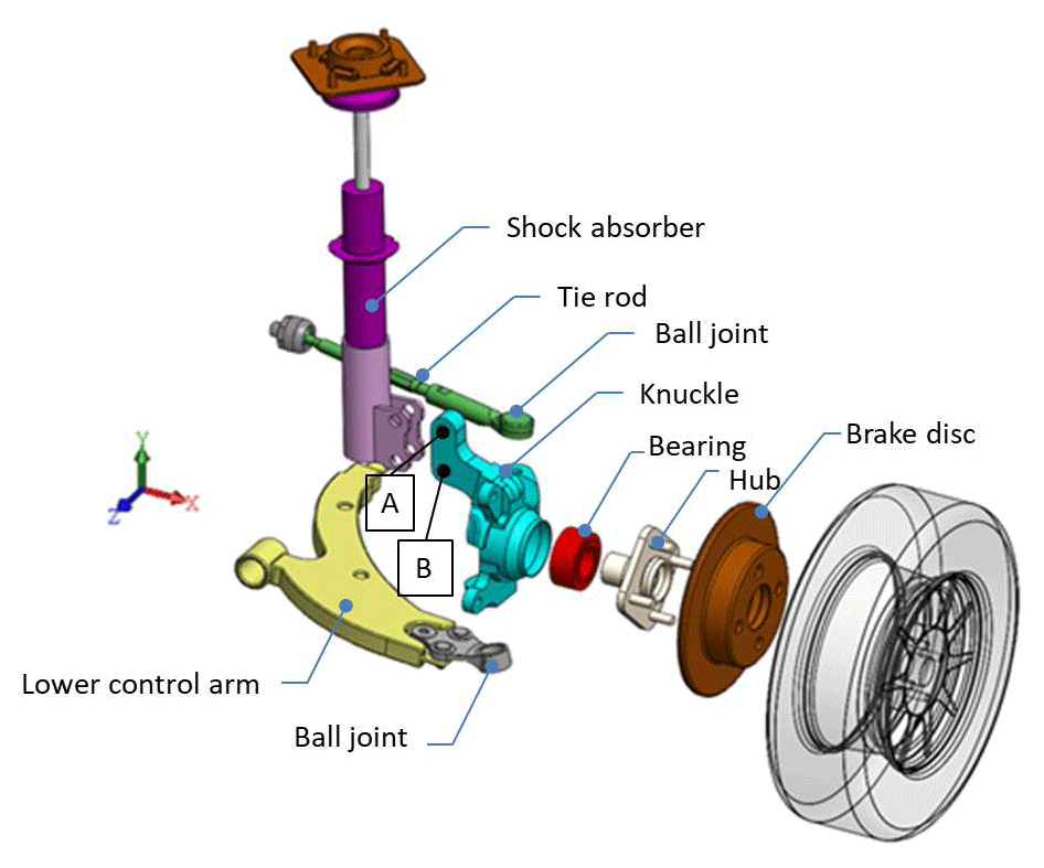
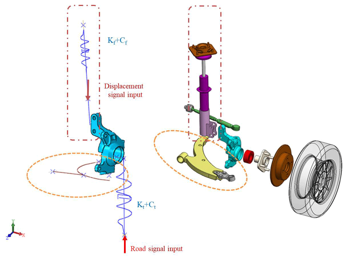
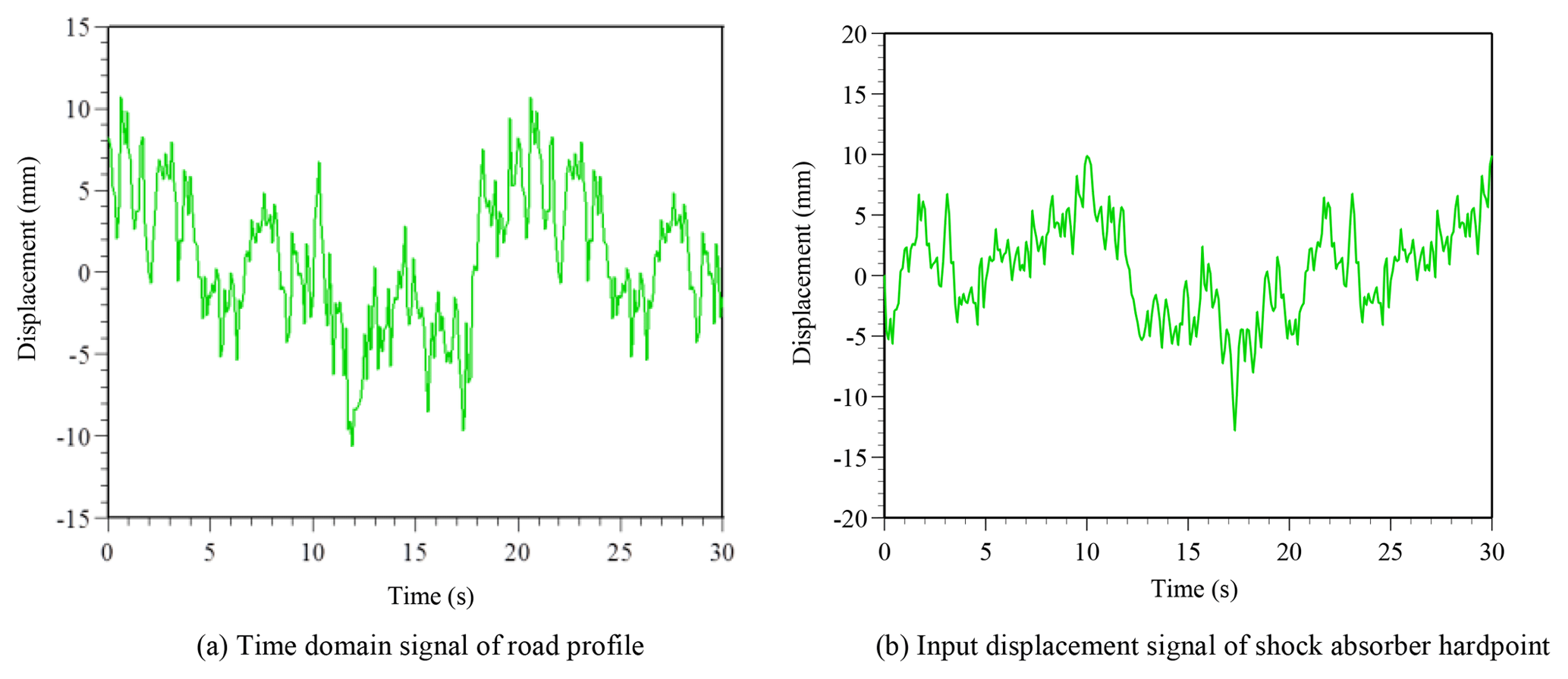
Figure 12Road profile signal (class A) and corresponding input displacement signal to shock absorber hardpoint. (Note that vehicle velocity V is equal to 40 km h−1.)
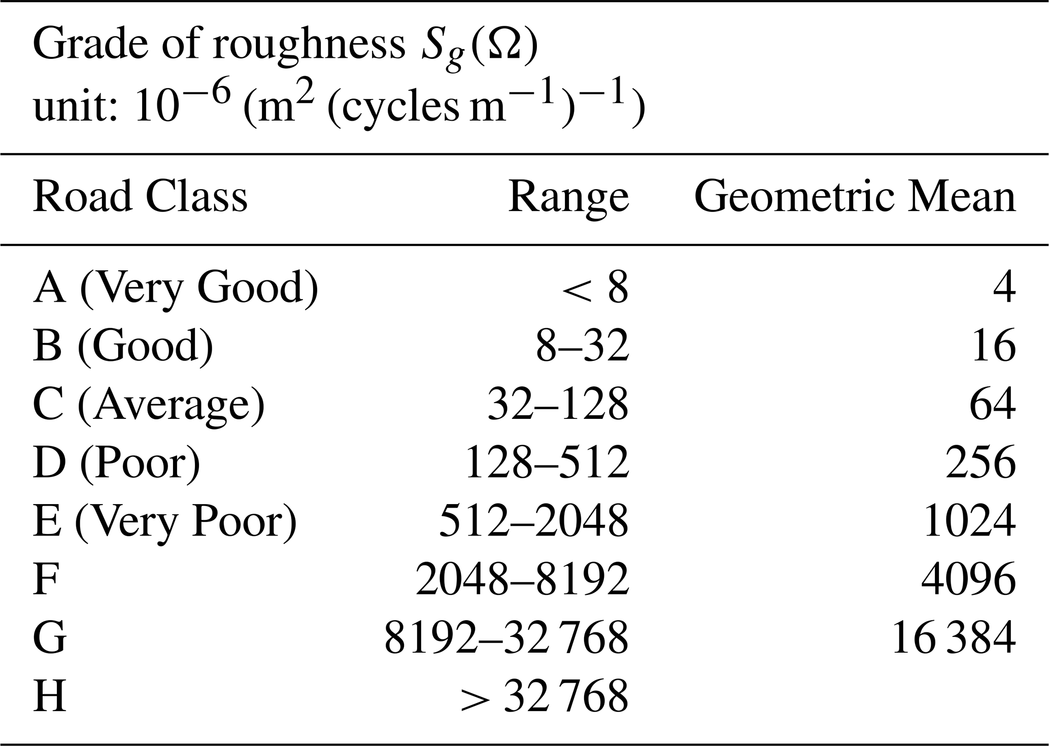
The input road signal was modeled using the road surface profile specification established in ISO, in which the road surface roughness is expressed as a power spectral density function of the road surface displacement and comprises a total of 8 classes (A–H). According to the ISO standard, the power spectral density function of the road displacement can be expressed in the following wave number form:
where Ω is the reciprocal of the wavelength (i.e., the wave number (cycle m−1) contained within a single unit length); is the reference wave number (cycle m−1); and Sg(Ω) is the roughness function of the road surface (cycle m−1). In addition, N1 is the frequency index related to the frequency structure of the road spectrum and has a value in the range of 1.75–2.25 with an average value of 2, N1=2. Table 3 shows the ISO roughness of the eight road classes (ISO 8608, 1995).
The ISO specification for the road roughness has the form of a frequency signal. However, the input to the tire system used in the present fatigue analyses should have the form of a time-domain signal. Thus, a Matlab program was used to convert the ISO-standard frequency domain signal into a time-domain signal in accordance with the following relationship (Soliman et al., 2006):
where X(t) is the displacement signal of the road profile and is composed of multiple sine waves of different frequencies; h is the number of sine waves, k is the current sampling point of the signal; V is the vehicle speed (m s−1); ψ is the phase angle; Sg(Ω) is the roughness value of the road surface class; δf is the frequency interval; f is the frequency; and n is the road surface roughness and usually has a value between 2 and 3.
Consider the general road surface level (class A) as an example and assume that the maximum speed of the target vehicle is V=40 km h−1. Assume further that the road surface is composed of h=1000 sine waves with a frequency interval of δf=0.05 Hz. In other words, the road surface covers the frequency range of 0.05 to 50 Hz. According to Table 3, the maximum value can be used as the input of the road grade, Sg(Ω). Therefore, the Sg(Ω) values of classes A, B, C and D road roughness are 8, 32, 128 and 512, respectively. From Eq. (3), the time domain signal of the road surface profile (class A) can be obtained with the form shown in Fig. 12a. The corresponding input displacement signal applied to the shock absorber hardpoint is shown in Fig. 12b.
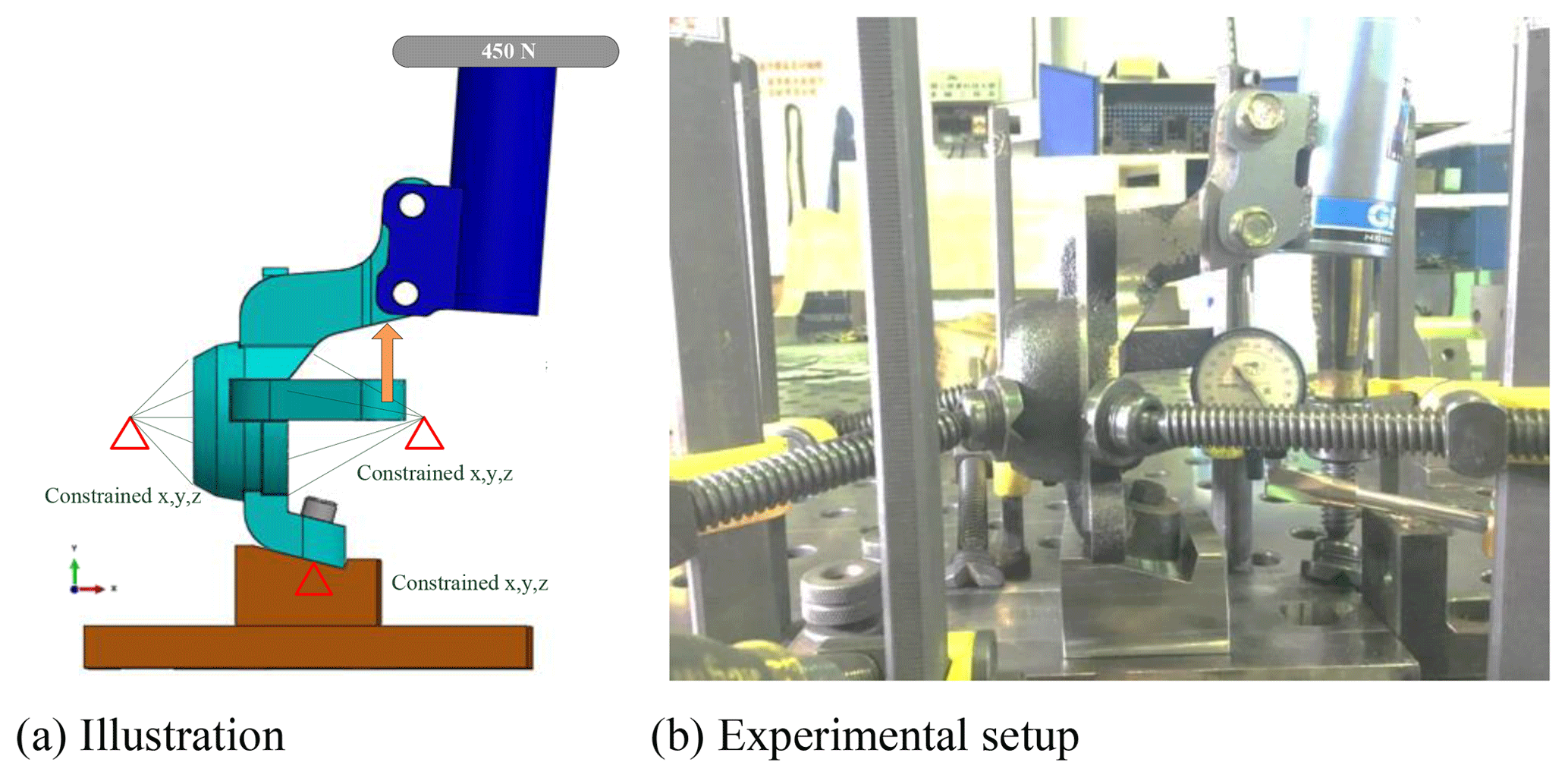
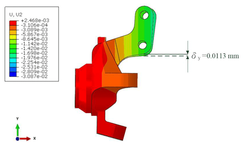
To ensure the validity of the FE model and confirm the feasibility of the designed knuckle, the deformation of the knuckle in the actual EV was measured under the application of a load of 450 N in the downward y direction at the upper shock mount with fixed constraints applied in the x, y and z directions at the lower control arm hardpoints and at the wheel center position of the knuckle (see Fig. 13). The results obtained using a dial gauge placed under the strut showed that the strut arm underwent a displacement of 0.0117 mm. Under the same load and constraint conditions, the FE model showed a displacement of 0.0113 mm (see Fig. 14). This value is broadly similar to the experimental result, and hence the basic validity of the FE model is confirmed (see Fig. 15). Notably, the displacement predicted by the FE model for the redesigned knuckle is less than that observed for the actual knuckle. Thus, it is further confirmed that the strength of the redesigned knuckle meets the requirements of the commercial knuckle.
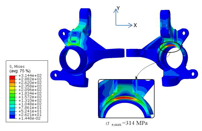
In performing the impact load analysis, the boundary conditions and applied load were set as shown in Fig. 9. Moreover, the upward force acting on the knuckle in the y direction was set as 3.5 G (see Table 1). Figure 16 shows the simulation results for the resulting von Mises stress distribution. It is seen that the regions of maximum stress are located mainly under the knuckle strut arm and at the corners of the strut arm ribs. From inspection, the von Mises stress () has a maximum value of MPa. This value is less than the material yield stress (370 MPa), and hence the mechanical integrity of the knuckle under the considered impact load is confirmed.
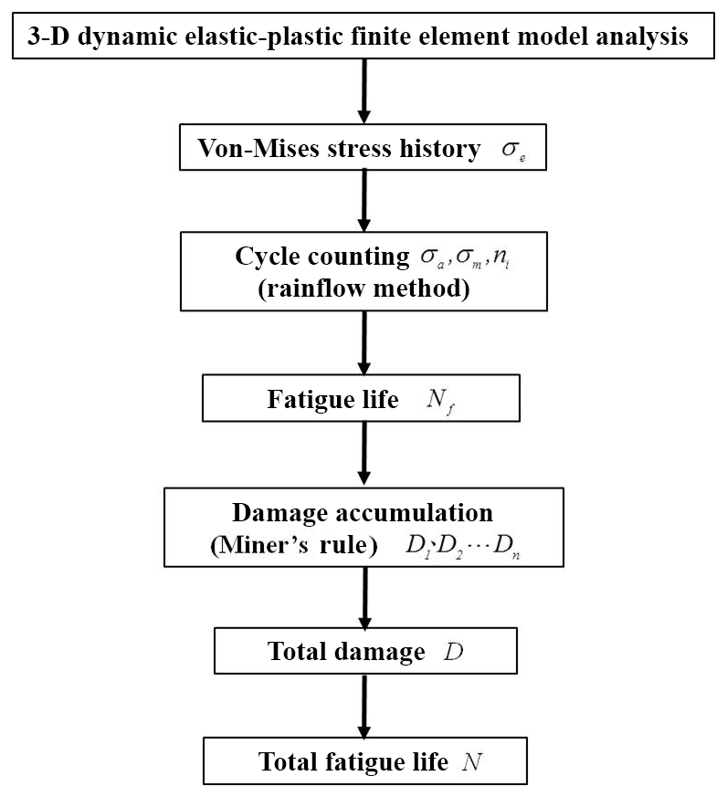
A further series of simulations was performed to evaluate the fatigue life of the knuckle under road classes A, B, C and D. For each road class, the stress distribution in the knuckle structure was simulated using the 3-D dynamic elasto-plastic FE model. Following the analysis process, the stress history at the point of maximum von Mises stress was taken and the rain flow counting method was used to count the number of occurrences of the maximum stress. The fatigue life, Nf, was then calculated in accordance with the occurrences ni of amplitude σa corresponding to the average stress σm. Finally, Miner fatigue theory was used to accumulate the fatigue damage values under various fatigue strengths in order to calculate the total fatigue life of the knuckle (see Fig. 16).
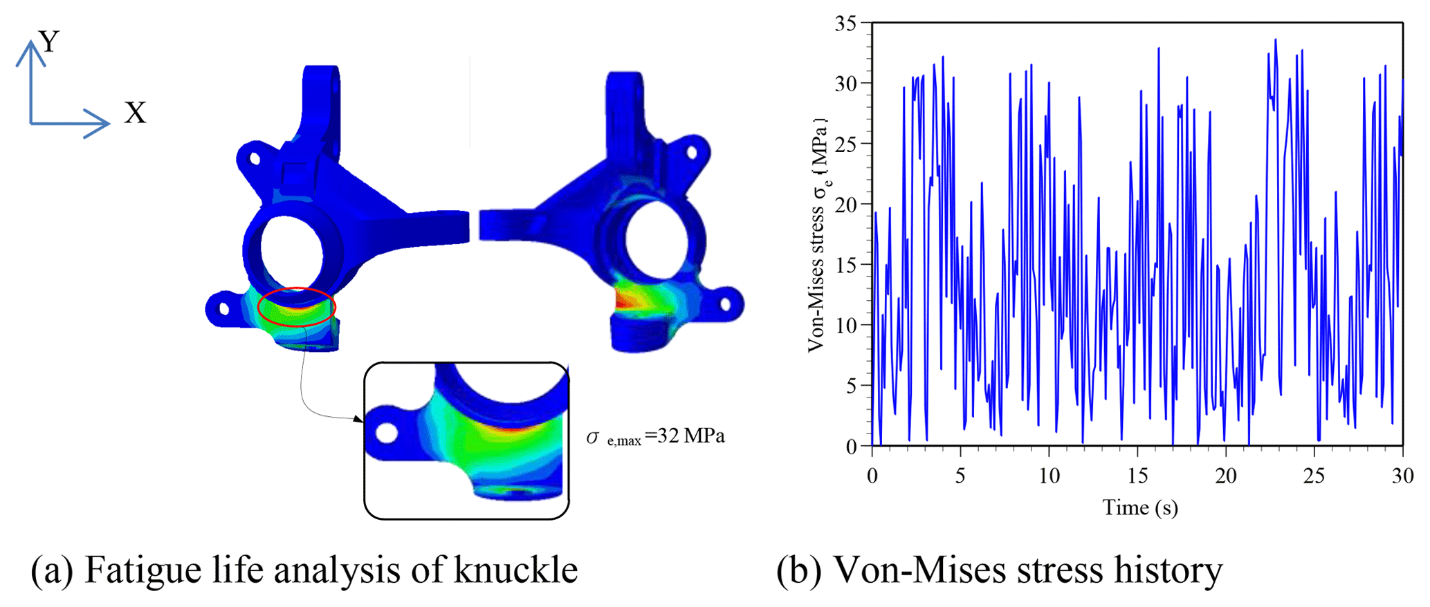
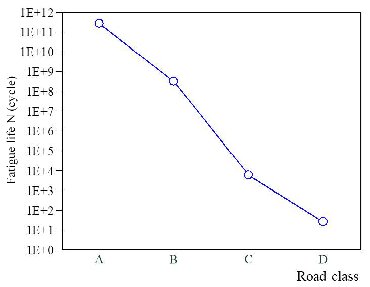
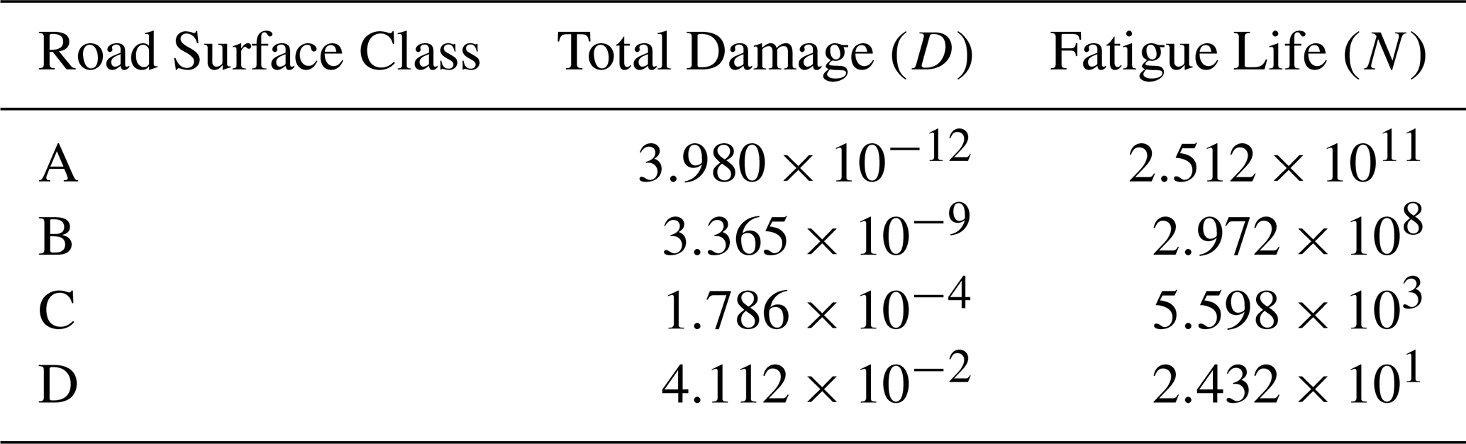
At a vehicle speed of 40 km h−1, the maximum amplitudes of the road surface in the time-domain signal diagrams are approximately 10, 25, 50 and 100 mm for road classes A, B, C and D, respectively. Figure 17a shows the von Mises stress distribution in the re-designed knuckle for the class A road surface. It can be seen that the von Mises stress reaches a maximum value of 32 MPa at a point just beneath the knuckle cone. Figure 17b shows the von Mises stress history at the corresponding location. Substituting the stress history results into FE-Safe, the fatigue life is found to be cycles. The fatigue life is greater than 1×10⁶ cycles, and hence the knuckle can be assumed to have an infinite life when operating on a Class A road. Table 4 and Fig. 18 summarize the fatigue test results for road classes A–D. As expected, the fatigue life reduces with an increasing road roughness. However, in general, the results show that the knuckle has an infinite life for general road classes (A and B)
Table 4Fatigue life of knuckle for various road classes and vehicle speed of 40 km h−1.
This study has proposed a systematic framework for the design and analysis of a lightweight knuckle for a commercial electric vehicle (EV). In the proposed framework, the design space is identified from an inspection of the steering and suspension systems of the target EV and a hardpoints sensitivity analysis. A finite element model of the knuckle is constructed in ABAQUS and two-stage topology optimization is then performed to minimize the weight of the knuckle. Finally, finite element simulations are conducted to analyze the strength of the knuckle and evaluate its fatigue life under four ISO 8608 road classes (A–D). The simulation results support the following main conclusions:
The original knuckle has a weight of 3.88 kg. By contrast, the redesigned knuckle has a weight of just 3.64 kg for the same material and strength constraints. In other words, the redesigned knuckle achieves a weight saving of approximately 6.2 %.
Under impact load conditions, the knuckle is capable of bearing 3.5 G in the vertical direction. The maximum von Mises stress has a value of MPa and occurs beneath the knuckle strut arm. The maximum stress is less than the yield strength of the knuckle material (GCD450). Hence, the mechanical integrity of the knuckle under impact loads is ensured.
The fatigue life analysis results show that the redesigned knuckle has fatigue lives of 2.512×10¹¹, 2.972×10⁸, 5.598×10³ and 2.432×101 under ISO 8608 road classes A, B, C and D, respectively. For general road classes (A and B), the fatigue life is greater than 1×10⁶ cycles, and hence the knuckle can be regarded as having an infinite life.
All the experimental data can be obtained from the author.
YCC and HHH conceived of the presented idea. We developed the theory and CWW performed the CAE. YCC and HHH verified the analytical methods and supervised the findings of this work. All authors discussed the results and contributed to the final manuscript.
The authors declare that they have no conflict of interest.
This research was supported by MOST (project no. MOST 107-2637-E-020-001).
This paper was edited by Guimin Chen and reviewed by Shuang Xu and three anonymous referees.
Bhardwaj, S., Ashok, B., Lath, U., and Agarwal, A.: Design and Optimization of Steering Upright to Reduce the Weight Using FEA, SAE Technical Paper 2018-28-0081, SAE International, USA, https://doi.org/10.4271/2018-28-0081, 2018.
Fan, P., Zhao, B., and Qiu, L.: The Analysis on Destruction Forms of Steering Knuckle, Third International Conference on Measuring Technology and Mechatronics Automation, IEEE, Shanghai, China, Vol. 3, 677–679, https://doi.org/10.1109/ICMTMA.2011.740, 2011.
ISO 8608: Mechanical Vibration – Road Surface Profiles – Reporting of Measured Data, International Standardization Organization, Geneva, Switzerland, 1995.
Muhamad, W. W., Sujatmika, E., Hisham, H., and Tarlochan, F.: Design Improvement of Steering Knuckle Component Using Shape Optimization, International Journal of Advanced Computer Science, 2, 65–69, 2012.
Shelar, M. L. and Khairnar, H. P.: Design Analysis and Optimization of Steering Knuckle using Numerical Methods and Design of Experiments, International Journal of Engineering Development and Research, 2, 2958–2967, 2014.
Sivananth, V. and Vijayarangan, S.: Fatigue Life Analysis and Optimization of A Passenger Car Steering Knuckle under Operating Conditions, International Journal of Automotive and Mechanical Engineering, 11, 2417–2429, https://doi.org/10.15282/ijame.11.2015.22.0203, 2015.
Soliman, A. M. A., Abd Alla, S. A., El-Mashed, Y. A., and Hamid, M. S. A.: Improvement of Vehicle Ride Performance Using a Hydro-pneumatic Active Suspension System, SAE Technical Paper No. 2006-01-1298, SAE International, USA, https://doi.org/10.4271/2006-01-1298, 2006.
Song, C. Y. and Lee, J.: Reliability-based Design Optimization of Knuckle Component using Conservative Method of Moving Least Squares Meta-models, Probabilist. Eng. Mech., 26, 364–379, https://doi.org/10.1016/j.probengmech.2010.09.004, 2011.
Vijayarangan, S., Rajamanickam, N., and Sivananth, V.: Evaluation of Metal Matrix Composite to Replace Spheroidal Graphite Iron for a Critical Component Steering Knuckle, Materials and Design, 43, 532–541, https://doi.org/10.1016/j.matdes.2012.07.007, 2013.
Wang, J. X., Ou, K. H., Liu, S. H., and Chen, J. H.: Simulation of knuckle strength based on multi-body dynamics, Chang'an Automobile Engineering Research Institute CAE Department, Chang An, 2002.
Zoroufi, M. and Fatemi, A.: Fatigue Life Comparisons of Competing Manufacturing Process: A Study of Steering Knuckle, SAE Technical Paper Technical, No:1999-01-0344, SAE International, USA, https://doi.org/10.4271/2004-01-0628, 2004.