the Creative Commons Attribution 4.0 License.
the Creative Commons Attribution 4.0 License.
 | 07 Aug 2019
Removal mechanism of machinable ceramics and theoretical model of cutting force in turning operation
Tao Liu
Lianjie Ma
Ye Wang
Wei Bai
Hao Chang
The removal mechanism of machinable ceramics in turning was studied, and a theoretical model of cutting force based on energy theory was proposed. Based on the turning test of machinable ceramics and kinematics analysis of the tool-workpiece system, a model of tool-workpiece contact zone considering the tool tip arc radius was established. The crack propagation path and three stages of the crack development were analyzed from the stress perspective. Then the energy of the crack system was studied, and the brittle fracture energy which is more suitable for brittle materials was put forward. Based on the principle of energy conservation, a correction theoretical model of cutting force was established, which was verified by turning experiments of machinable ceramics. The results indicated that the predicted values of the model were in good agreement with the experimental values. Both theoretical model and experimental results demonstrated that the cutting force decreased as cutting speed increased, and increased as cutting depth and feed rate increased. This model enabled an in-depth understanding of the interaction action between the cutting tool and work materials involved in the turning of machinable ceramics.
- Article
(2112 KB) - Full-text XML
- BibTeX
- EndNote


The machinability of machinable ceramics is superior to that of ordinary ceramics due to its superior physical, chemical and mechanical properties. It has a broad application prospect in aerospace, military, chemical and other fields (Ma et al., 2014). Turning machinable ceramics has many advantages, such as high efficiency and low cost, which is of great significance to the large-scale application of machinable ceramics. Cutting force is one of the most important factors in cutting process, which plays an important role in predicting machining quality and controlling machining precision (Huang et al., 2010; Li et al., 2016).
At present, grinding is the main processing method, so there are many studies on grinding force model. Liu et al. (2012) studied the cutting mechanism of rotary ultrasonic grinding of brittle materials, and considered that the main removal mechanism of brittle materials was brittle fracture, and established the cutting force model of rotary ultrasonic grinding of brittle materials. Wu et al. (2016) considered that both ductility removal and brittleness removal existed in the grinding process of brittle materials, and proposed the grinding force model of brittle materials under the combined action of ductility removal force and brittleness removal force; Xie et al. (2008, 2011) analyzed two removal methods of plastic deformation and brittle fracture of engineering ceramics, studied the relationship between cutting deformation force and material properties and grinding parameters, and established the grinding force model of high-speed deep grinding of engineering ceramics; Lin et al. (2012) studied the stress changes of elastic deformation, plastic deformation and crack initiation in the process of material removal, and established a single abrasive grinding force model based on stress concentration theory; Li et al. (2018) established the micro-grinding force model of reaction-bonded silicon carbide (RB-SiC) ceramics by considering the brittle fracture of materials, grinding conditions and random distribution of abrasive particles in grinding wheels; Zhang et al. (2017) studied the contact behavior of a single abrasive particle with work piece material at different grinding depths, analyzed the material removal mechanism and plastic accumulation mechanism, determined the critical transition between plow and cutting, and established an improved theoretical model of grinding force. Sun et al. (2018) studied axial ultrasonic vibration assisted peripheral grinding (AUPG) glass-ceramics. Considering the material removal mechanism, material mechanical properties and vibration effects, three stages of material removal, friction process, toughness removal and brittleness removal were established respectively.
The research on cutting force model in turning mainly focuses on empirical model and prediction model. Szecsi (1999) proposed the cutting force model of metal material based on artificial neural network as early as 1999, and used error back-propagation algorithm to train the multi-layer feedforward neural network. Sharma et al. (2008) analyzed the influence of metal turning parameters on three cutting force components and surface roughness, and established a neural network-based cutting force and surface roughness estimation model; Alajmi and Alfares (2007) adopts differential evolutionary algorithm to train and BP neural network to predict cutting force; Ma et al. (2016) modified the material constitutive model, and established the cutting force prediction model based on genetic algorithm and neural network.
The theoretical model plays an irreplaceable role in the study of cutting process, so it is necessary to study the theoretical model of cutting force. Ma et al. (2017a, b) proposed two kinds of chip forming methods for turning hard and brittle materials. By analyzing the micro-fracture mechanism of ceramic materials, the energy models of crack system were established, and then the theoretical model of turning force for hard and brittle materials was established. However, this study neglects the arc of the tool tip and considers that the ideal point contact between the tool and the material is not enough in-depth study of the energy model, and there is a deviation from the actual value.
In this paper, the tool-workpiece contact area with tool tip arc radius is established by kinematics analysis of the tool-workpiece system. Based on the stress theory and the machined surface topography, the crack deflection angle during turning of brittle materials is deduced, and then the whole crack propagation path is obtained. Based on energy theory, the energy conservation relationship between cutting force work and crack system energy is established. Griffith theory is used to study the energy of crack system. Griffith theory considers that the material is elastic deformation before fracture, but the fracture process of machinable ceramics is quite different from it. In this paper, brittle fracture energy is proposed to modify the theory, and finally the correction model of machinable ceramics turning force is established.
2.1 Tool-workpiece contact zone model with corner radius
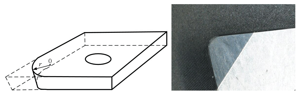
Previous cutting force models considered the tool as an ideal tool and its tip as a point, but there is a corner radius in the actual tool. When cutting brittle materials, the cutting depth is very small, and the corner radius can not be ignored. Therefore, this paper studies the influence of corner radius on cutting process. After considering the corner radius, the actual shape of the tool tip has changed, and the contact area with the workpiece has also changed. The corner radius is shown in Fig. 1. The dashed part is the ideal tool shape, the solid part is the actual tool shape, and the corner radius is r.
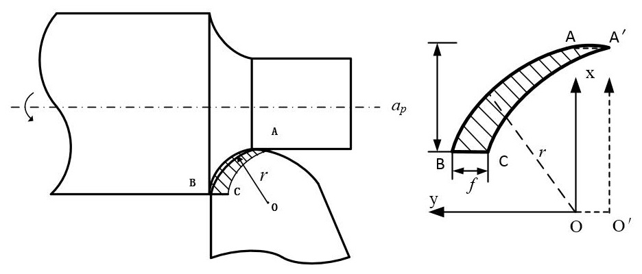
The tool-workpiece contact area and chip shape have changed compared with the previous model, and the contact area morphology needs to be re-determined. As shown in Fig. 2, the tool-workpiece contact area is the area between arc AB and arc AC. The size of the contact area is related to corner radius, cutting depth and feed rate.
When the workpiece is rotated once, the radius center of the turning tool arc moves from O to O′, and the rectangular coordinate system is established with O as the center. The contact area S is:
where f is the feed rate, r is the arc radius of the tool tip, and ap is the cutting depth.
2.2 Crack propagation path of machinable ceramics
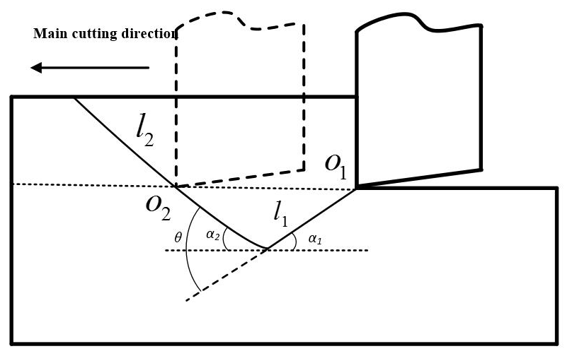
The main material removal mechanism in turning ceramics is crushing removal, as shown in Fig. 3. The process of crack propagation can be divided into two stages. The first stage is that the tool contacts with the workpiece and produces cracks that propagate into the workpiece, forming crack l1. The second stage is that when the crack reaches the limit depth, it turns to the workpiece surface to propagate until the crack l2 is formed on the workpiece surface.
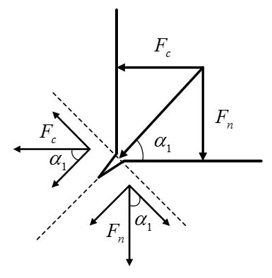
In the first stage, the crack is subjected to both the main cutting force and the cutting resistance. As shown in Fig. 4, the main cutting force and the shear resistance can be decomposed into the force component along the crack direction and the force component in the vertical crack direction, and the force components in the vertical crack direction are equal and opposite. The force components along the direction of the crack are the same, and the effect on the crack growth can be neglected. Therefore, the crack system can be regarded as a typical mode-I crack.
According to Griffith theory, there is a limit depth for crack propagation to the workpiece, and the critical condition for mode I crack propagation is as follows:
where E is the modulus of elasticity, γ0 is the surface energy, and C is the length of crack.
The stress σ is inversely proportional to the crack length C, so the stress at the ultimate depth is the minimum stress value of the first stage crack growth. This paper considers that the critical stress value σF is the critical stress value of mode-I crack growth. The tool will not contact with the machined surface cracks in the cutting process, so the pits can be measured on the machined surface. The crack extended angle α1 and the crack limit depth h can be obtained by measuring the shape of the pits.
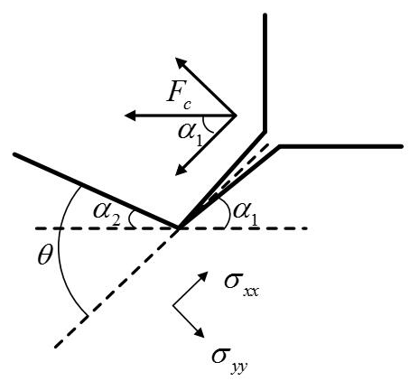
When the ultimate depth is reached, the cutting resistance will not affect the crack propagation path. At this time, only the main cutting force affects the crack propagation path. Under the action of the main cutting force, the crack deflects and then propagates to the surface of the workpiece. The crack can be regarded as a typical mode-II crack only under the action of the main cutting force, as shown in Fig. 5.
Based on Irwin theory, the stress of mode-II crack in yy direction is
When the crack deflects, the stress at the tip is the same as that at the first stage of critical propagation.
Crack deflection angle θ satisfies the following conditions:
Therefore, the crack extended angle α2 for crack l2 is:
In the turning process, there is a conservation of energy between the turning tool and the workpiece, that is, the work done by the cutting force is equal to the energy required for the formation of the crack system.
3.1 Doing work by cutting force
During the time of crack initiation and propagation, the work done by the main cutting force is:
The ultimate crack growth speed of brittle material is (Roberts and Wells, 1954), and the crack length is when a primary fracture occurs, so the crack growth time is:
where h is the depth of concave pit on the surface of workpiece, and ρ is the density of material.
3.2 Energy of crack system
Griffith theory is the most classical method to study the energy change of crack system. Griffith theory holds that the energy of crack system includes mechanical energy and surface energy, as follows:
where U is the energy of crack system, UM is the mechanical energy of system, US is the surface energy.
Griffith theory holds that the experimental material is an ideal elastic body before fracture and strictly meets Hooke's law. The material used in this paper is a typical brittle material. Although there is a very small deformation before fracture, it is impossible to distinguish the critical point of elastic-plastic deformation, and the deformation can not be measured directly, so the mechanical energy of the system can not be calculated according to the elastic deformation.
This paper considers that the energy input before the crack generation is stored in the workpiece in the form of material deformation potential energy (including elastic potential energy and plastic potential energy). There is a critical value of potential energy stored per unit volume of workpiece. When the critical value exceeds, the workpiece cracks and releases excess energy in the form of surface energy. In this paper, the critical value of potential energy is called brittle fracture energy UC. The brittle fracture energy is related to the critical stress produced by crack and the volume of material. In the turning process, ceramics are mainly crushed under pressure, so the critical stress caused by material cracks can be expressed by compressive strength. The expression of brittle fracture energy is:
where σ is the critical strength of the material when it breaks, and V is the volume of the material when it breaks.
During cutting, stress concentration occurs in the contact area between workpiece and tool tip, and the critical stress for cracking in this area is less than the compressive strength of the material. The contact area of the tool tip is not an ideal point, but an arc, as shown in Fig. 6. Based on Inglis' stress theory, the stress concentration factor in the stress concentration area is as follows:
where k1 is the stress concentration factor and rd is the edge radius at the tool tip.
The cutting resistance also causes stress concentration in the contact area of the tool tip. At this time, the workpiece can be regarded as the bending of a circular rod with shoulder. The stress concentration factor k2 can be obtained by referring to the stress concentration manual. In this experiment, k2 is taken as 1.3. The actual stress concentration factor at the tool tip is:
In the first stage, the chip volume is approximately columnar, the contact area is S, and the height is . In the second stage, the chip volume is approximately conical, the contact area is S, and the height is . The brittle fracture energy of the system is:
When a new crack occurs, the increased surface area is:
Therefore, the surface energy of the crack system is:
where Cγ0 is the surface energy of the material in unit area.
3.3 Cutting force model of machinable ceramics
According to the energy conservation relation, the work done by the external cutting force is equal to the energy of the crack system, as follows:
The final cutting force model is:
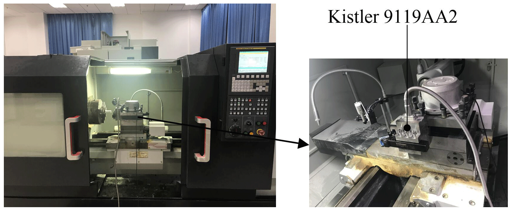
In this experiment, fluorophlogopite ceramics were selected as the workpiece. Its Young's modulus is 200 GPa, fracture toughness is 3.8 MPa m1∕2, density is 2.56 g cm−3, free surface energy per unit area is 0.54 J m−2 and compressive strength is 108 MPa. The diameter of the workpiece is 30 mm. Turning experiments were carried out on CAK5085 machine lathe. CBN turning tool was used. The main deviation angle κr is 92∘ and the secondary deviation angle is 33∘, the front angle γ0 is 0∘, the rear angle α0 is 11∘, the blade inclination angle λs is 0∘, the tool tip corner radius r is 0.5 mm, and the tool tip edge radius is 0.02 mm.
The cutting force was measured by a six-component cutting force testing system produced by Kistler Company in Switzerland, and the average value of the main cutting force in the stable stage of cutting was selected as the valid data. The turning experiment and cutting force test field are shown in Fig. 7.
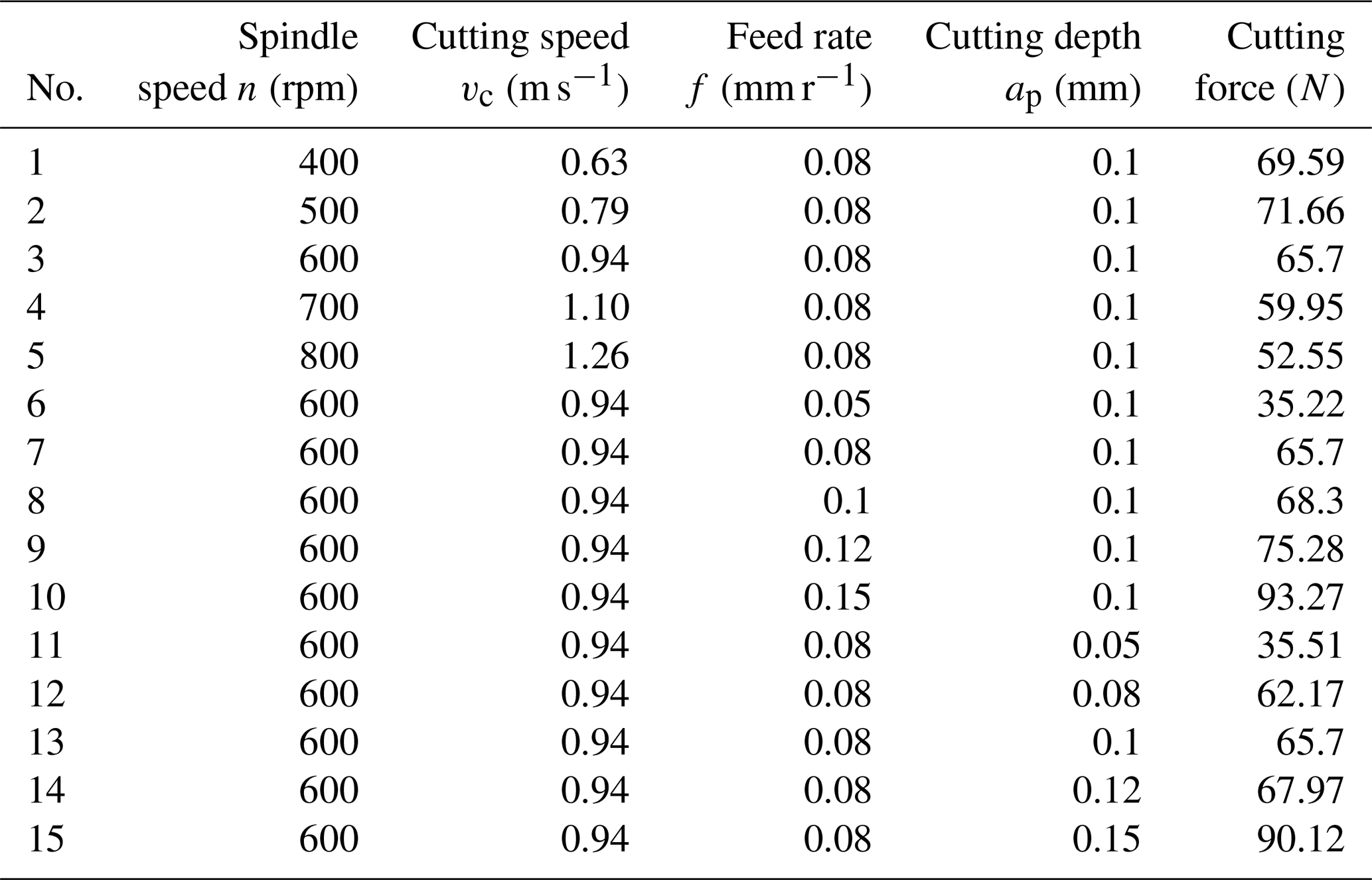
A single factor experiment was designed to study the influence of cutting speed, feed rate and cutting depth on cutting force. The experimental data of single factor and cutting force are shown in Table 1. The third group is the control group, which is the same as the data of group 7 and 13.
Table 1Single-factor experimental conditions for fluorinated mica ceramics.
5.1 Morphology of machined surface cracks
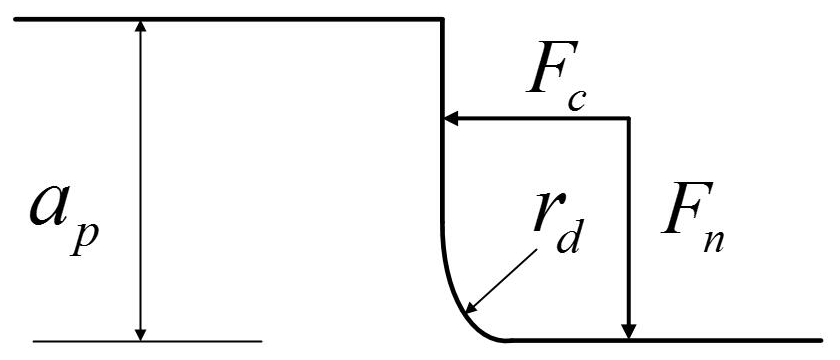
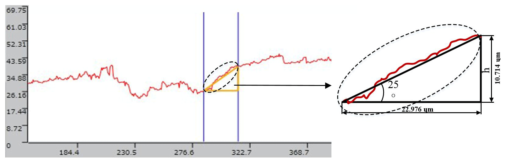
The turning tool does not contact the machined surface during the first cutting process, so the crack propagation path can be obtained by measuring the machined surface morphology. The machined surface morphology of fluorite mica ceramic workpiece was measured by OLS4100X 3-D laser confocal microscopy system. According to the obtained profile of the pit section, the pit depth h and the initial crack growth angle α1 in the first stage were measured. Figure 8 shows the profile information of a typical pit section.
After many measurements, the pit depth h is 10.22 µm, and the crack initiation angle α1 is 25∘ in the first stage. Substitution of material properties and surface parameters of pits into Eq. (5) the deflection angle θ of the crack is 74.05∘, and the propagation angle α2 of the crack in the second stage is 49.05∘.
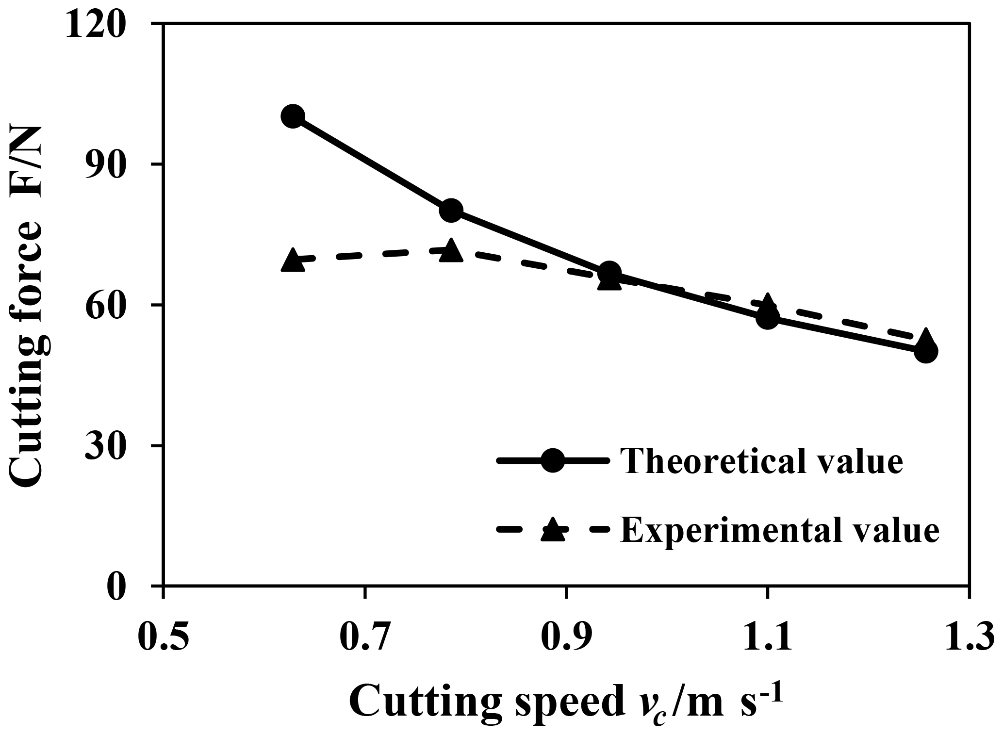
5.2 Effect of cutting speed on cutting force
In order to study the influence of cutting speed on cutting force, the feed rate f is 0.08 mm r−1 and the back feed ap is 0.1 mm, as shown in Fig. 9. The research object of this model is the cutting force in the process of primary crack growth. According to the principle of energy conservation, the faster the cutting speed is, the smaller the cutting force is required, so the cutting force decreases as cutting speed increased. When the cutting speed is low, the material removal form is ductile domain removal. The research content of this model is brittle domain removal, so the error is large when cutting speed is low. When the cutting speed is high, the predicted value of the model is in good agreement with the experimental value.
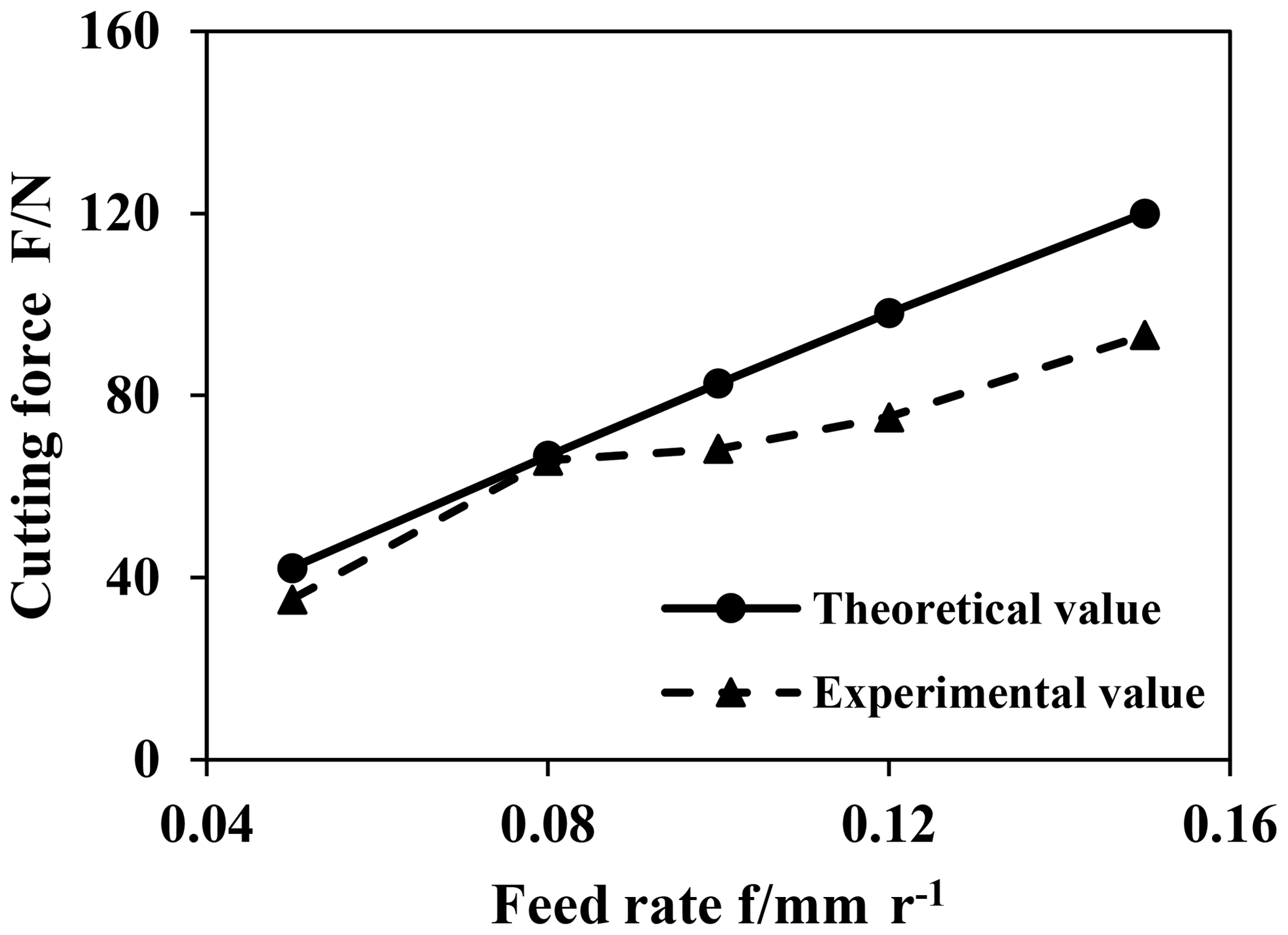
5.3 Effect of feed rate on cutting force
The variation trend of cutting force with feed rate is shown in Fig. 10. At this time, the cutting speed n is 600 r min−1 and the cutting depth ap is 0.1 mm. With the increase of feed rate, the cutting force increases gradually. When the feed rate is low, the predicted value of the model is close to the experimental value. When the feed rate is high, the predicted value is larger than the experimental value. Because the micro-cracks will occur in the feed direction of the turning tool, but the main cutting speed of the turning tool is much larger than the feed rate, the micro-cracks have little influence on the energy of the crack system, so the model has not studied these micro-cracks.
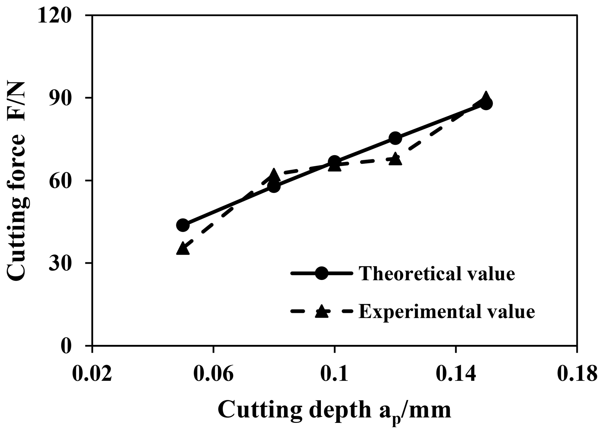
5.4 Effect of cutting depth on cutting force
The influence of cutting depth on cutting force is shown in Fig. 11. At this time, the cutting speed n is 600 r min−1 and the feed rate f is 0.08 mm r−1. In this model, the crack propagation time varies with the cutting depth. In order to control the research variables, the same crack propagation time was selected in the calculation. As the cutting depth increases, the chip volume removed in one cutting process increases and the energy required increases, so the cutting force increases as cutting depth increased.
-
A model of tool-workpiece contact zone considering the corner radius was established, the model indicated that when the cutting depth was close to the corner radius, the influence of the arc radius could not be ignored.
-
Crack propagation path in turning brittle materials is related to material properties and stress distributions.
-
Brittle fracture energy was proposed to describe the potential energy stored before cracks occurring, and the predicted error was relatively large when only the change of elastic potential energy during material removal process was considered. There are elastic and plastic deformation regimes before the generation of brittle cracks. The work done by external forces was stored in materials in the form of potential energy. The critical value is brittle-fracture energy, which is the inherent property of the materials.
-
Based on the energy conservation relationship between the input energy of the turning tool and energy of crack system, a theoretical model of cutting force during turning brittle materials was established. The model demonstrated that the cutting force was inversely proportional to the cutting speed and directly proportional to the cutting depth and feed rate.
The data that support the findings of this study are available from the corresponding author, Lianjie Ma, upon reasonable request.
TL and LM conceived and designed the study. TL, YW, HC, and WB performed the experiments. TL and LM wrote the paper. TL, LM, and YW reviewed and edited the manuscript. All authors read and approved the manuscript.
The authors declare that they have no conflict of interest.
This research has been supported by the National Natural Science Foundation of China (grant no. 51275083) and the Natural Science Foundation of Hebei Province (grant no. E2018501078).
This paper was edited by Bahman Azarhoushang and reviewed by two anonymous referees.
Alajmi, M. S. and Alfares, F.: Prediction of cutting forces in turning process using de-neural networks, Conference on Proceedings of the Iasted International Multi-Conference: Artificial Intelligence and Applications, ACTA Press, 41–46, 2007.
Huang, H., Lin, S., and Xu, X.: Study on Grinding Forces for Glass Grinding with Single Diamond Grit, China Mechanical Engineering, 21, 1278–1282, 2010.
Li, C., Zhang, F., Meng, B., Liu, L., and Rao, X.: Material removal mechanism and grinding force modelling of ultrasonic vibration assisted grinding for SiC ceramics, Ceram. Int., 43, 2981–2993, 2016.
Li, Z., Zhang, F., Luo, X., Guo, X., Cai, U., Chang, W., and Sun, J.: A New Grinding Force Model for Micro Grinding RB-SiC Ceramic with Grinding Wheel Topography as an Input, Micromachines, 9, 368, https://doi.org/10.3390/mi9080368, 2018.
Lin, K., Xu, X., Li, Y., and Fang, C.: Model of grinding force based on stress concentration theory, Transactions of the Chinese Society for Agricultural Machinery, 43, 261–266, 2012.
Liu, D. F., Cong, W. L., and Pei, Z. J.: A cutting force model for rotary ultrasonic machining of brittle materials, Int. J. Mach. Tool Manu., 52, 77–84, 2012.
Ma, L., Gong, Y., and Chen, X.: Study on surface roughness model and surface forming mechanism of ceramics in quick point grinding, International Journal of Machine Tools and Manufacture, 77, 82–92, 2014.
Ma, L., Li, C., Chen, J., Li, W., Tan, Y., Wang, C., and Zhou, Y.: Prediction model And Simulation Of Cutting Force In Turning Hard-Brittle Materials, Int. J. Adv. Manuf. Tech., 91, 165–174, 2016.
Ma, L., Yadong, G., Li, Gu., Hua, W., Junchao, T., and Liang, L.: Mechanism of Surface Forming in Grinding Machinable Glass Ceramics, J. Mech. Eng., 53, 201–207, 2017a.
Ma, L. J., Yu, A. B., and Chen, J.: Theoretical model of cutting force in turning the lithium disilicate glass-ceramic, Int. J. Adv. Manuf. Tech., 92, 1–12, 2017b.
Roberts, D. K. and Wells, A. A.: The velocity of brittle fracture, Engineering, 178, 820–821, 1954.
Sharma, V. S., Dhiman, S., Sehgal, R., and Sharma, S. K.: Estimation of cutting forces and surface roughness for hard turning using neural networks, J. Intell. Manuf., 19, 473–483, 2008.
Sun, G., Zhao, L., Ma, Z., and Zhao, Q.: Force prediction model considering material removal mechanism for axial ultrasonic vibration-assisted peripheral grinding of Zerodur, Int. J. Adv. Manuf. Tech., 2775–2789, 2018.
Szecsi, T.: Cutting force modeling using artificial neural networks, J. Mater. Process. Tech., 92–93, 344–349, 1999.
Wu, C., Li, B., Yang, J., and Liang, S.: Prediction of grinding force for brittle materials considering co-existing of ductility and brittleness, Int. J. Adv. Manuf. Tech., 87, 1–9, 2016.
Xie, G. Z., Huang, H., Sheng, X. M., and Mi, H. Q.: Investigation on the grinding force and the ground damages in the high efficiency deep grinding of advanced ceramics, Journal of Hunan University, 35, 26–30, 2008.
Xie, G., Shang, Z., Sheng, X., Wu, Y., and Yu, J.: Grinding force modeling for high-speed deep grinding of engineering ceramics, Chin. J. Mech. Eng., 47, 169–176, 2011.
Zhang, Y., Li, C., Ji, H., Yang, X., Yang, M., Jia, D., Zhang, X., Li, R., and Wang, J.: Analysis of grinding mechanics and improved predictive force model based on material-removal and plastic-stacking mechanisms, Int. J. Mach. Tool Manu., 122, 81–97, 2017.