the Creative Commons Attribution 4.0 License.
the Creative Commons Attribution 4.0 License.
 | 17 Jul 2019
Analysis on the lateral vibration of drill string by mass effect of drilling fluid
Chunxu Yang
Ruihe Wang
Laiju Han
It is well known that the influence of the internal and external drilling fluid on the lateral vibration characteristics of drillstring cannot be ignored. In this paper, experiment apparatus for simulating drillstring vibration was established. Hammering method is used to measure drillstring lateral natural vibration frequency when the internal and external drilling fluid is considered. The test results show that the drilling fluid can decrease the natural frequency of the drillstring. Based on the simulation model, considering the influence of the internal and external drilling fluid, an external drilling fluid additional mass coefficient is derived considering the dynamic pressure effect caused by external drilling fluid. Additional mass coefficient can get the result with high precision, which can meet the needs of the project. the simulation results are in good agreement with the test results, and the error is within 2 %. This work provides a useful attempt and lays the foundation for the dynamics of the drill string in the drilling fluid environment.
- Article
(3312 KB) - Full-text XML
- BibTeX
- EndNote


It has been proved that drilling dynamics and its interactions with the surroundings is the essential reason of a lot of dangerous drilling accidents, such as the poor cementing quality induced by the deterioration of borehole quality and the failure of drilling tools caused by strong vibration (Ritto et al., 2013; Bailey and Finnie, 1960). As the most common dynamics phenomenon, severe vibrations of drillstring must be attached with great important to. Many dangerous problems related to drilling are caused by the drillstring dynamics and its interaction with the surrounding environment. As we all known that the drillstring failures is mainly due to the downhole vibrations. They can decrease rate of penetration (ROP), interfere with MWD tools and even cause premature fatigue of the components. The drillstring is consisted of several drill pipes, drill collars, stabilizers and connections, both are under heavy dynamic loads with extreme complexity. If the excited frequency of drillstring closes to the natural frequencies of its components, the energy will be absorbed. Once the resonance appears and the energy boosts, the amplitude of string vibration will be increased, and the bending of string will be intensified, by which the early fatigue of tools may be occurred, and the tools life will be reduced significantly. There are three typical modes of drillstring vibration, namely are the longitudinal vibration (also called axial vibration) mode, the transverse (also referred to lateral or bending) mode and the torsional (also known as stick-slip) mode. The destructive nature of each type of vibration is different. It is well known that lateral vibration (Mitchell et al., 1985; Zamudio et al., 1987) is the main reason for drilling string failure as the study of drill string dynamics goes further. Many dangerous phenomena related to drilling are normally caused by the dynamics of the drillstring and its interactions with the surroundings.
Wolf et al. (1985) measured down hole' parameters like bottom force and acceleration during vertical drilling, and it was found that resonant frequency of the system is lower than intrinsic frequency of drill string. The bending moment obtained by static simulation is one order of magnitude smaller than the real one, and a high bending moment was observed at the bottom which cannot be surveyed at the wellhead (Temple and Gillis, 1959). Robert F. Mitchell and Michael B. Allen developed that there is more lateral vibration than the longitudinal one at the bottom, BHA has the high bending moment, at the same time, the longitudinal vibration caused by axial vibration is not severe (Brebbia and Wrobel, 1979; Manolis and Polyzos, 1978). Researchers (Xue et al., 2016, 2019) studied the effect of annulus drilling fluid damping on drillstring lateral vibration, and it was found that the additional quality caused by drilling fluid is at the same order of magnitude of the quality of drillstring, which cannot be neglected. Drillstring lateral vibration under the efforts of drilling fluids both inside and outside using liquid and solid coupling vibration theory, and the drilling fluid can be generalized to quality distribution, so it cannot be neglected. The bottom drillstring lateral vibration is very common during sidetracking, and the lowest resonate frequency depended on material property and drill fluid features. M. W. Dykstra (Sarpkaya, 1979) utilized infinite element method, in combination with BHA statics buckling and dynamics vibration analysis and simulation of Sperry-Sun. After conducted a lot of experiment, he pointed that mass unbalance affect drillstring lateral vibration very much, and the friction between drillstring and well bore is severe when the drillstring move near its instinct frequency. Furthermore, the effect of drilling fluid in annulus on drillstring lateral instinct frequency under the small annulus clearance circumstances, drillstring lateral vibration frequency and bending stress amplitude increase with the decrease of annulus clearance.
Recently, many studies of the drillstring focused on the determination of natural frequencies (Chen and Géradin, 1995; Christoforou and Yigit, 1997), bending stress calculation (Graham et al., 1965; Plunkett, 1967), stability analysis (Vaz and Patel, 1995) and lateral displacement prediction (Yigit and Christoforou, 1998), etc. But the influence of the internal and external drilling fluid on the lateral vibration characteristics of drillstring is less of research literature. Additional mass force is on solid constructor caused mainly by the flow of surrounding liquid. The inertia mass which cause the additional mass force is called additional mass. Batchelor obtained algorithm of calculating additional mass using potential theory and calculated additional mass coefficient of different regular shapes. Brebbia and Wrobel (1979) applied boundary element method of solid mechanics to calculate velocity potential of flowing liquid, which make the algorithm easier. Sarpkaya (2004) developed that additional mass differed magnificently in different vibration amplitude after studied additional mass of cylinder vortex-induced vibration. Villaggo (1996) studied additional mass of infinite length cylinder with elastic deformation. However, no additional mass coefficient theory equation was obtained in all above. In this paper, simulation experiment apparatus was established, through experiment and numerical calculation, mass effect of drilling fluid inside and outside on drillstring vibration property was simulated and analyzed, which provide reference to the practical drillstring instinct vibration property.
In this paper, simulation and experiment apparatus for drillstring vibration was established. Hammering method is used to measure drillstring lateral natural vibration frequency when the internal and external drilling fluid is considered. The test results show that the drilling fluid can decrease the natural frequency of the drillstring, the simulation results are in good agreement with the test results, and the error is within 2 %.
2.1 Experiment apparatus
The Experiment apparatus designed as shown in Fig. 1, the experiment pipe (length 2 m) is suspended in the box by springs, and can be hinge supported in the box. The outside of the pipe is the housing, which is used to simulate the wellbore. There is a lid at each end of the pipe, so the drilling fluid can be only inside or outside of the pipe. Both ends are hinge supported when axial force is imposed. The height of the bolt can be adjusted in order to make sure that pipe is at the same axis with the box. The pipe is comprised of many sections which can be dismantled, and each section is connected and sealed by clamp with another. Each section of the outer tube (tubing diameter is 38 mm) corresponds to a measuring point position, two of the outer tubes are provided with holes to pass through the isolation tubes. Light isolation tube pastes through the hole in the test tube column, an isolation tube is placed in the acceleration sensor, another isolation tube for the hammer experiment. After the current position measuring point hammering test is finished, adjust the position of the outer tube with small holes to hammer test the next measuring point.
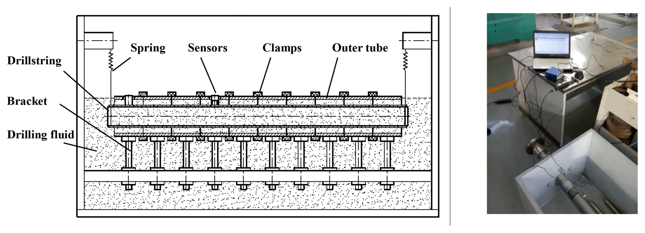
The data collection system is YMC9004 dynamic data collector. Dynamic data measurement and analysis software is YMC9800 modal analysis software, force hammer is IH-02, the hammer material is quartz, the sensor is 122A100 accelerator sensor with the characteristic of light weight and high sensitivity.
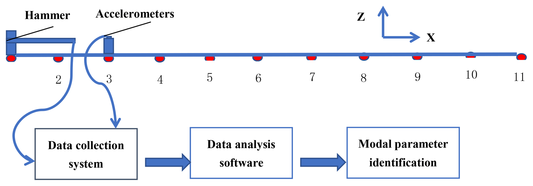
Experiments using multi-tap, single-point response method, the drill pipe × direction is divided into 10 equal parts, 11 measuring points, as show in Fig. 2. In order to better match the simulation results, we select the 3rd click point as the response point. Due to the large difference in size between the y and z directions and the x direction, it can be simplified as a bar, and only a few click points can be arranged in the x direction sequentially.
2.2 Modal analysis theory
According to the different measurement points on the drillstring, connecting the collection equipment to the experiment apparatus, using hammering test, the experiment is conducted under different experiment conditions, and the data were collected. During each test, take the average of three strikes to eliminate the influence of square deviation and error. Frequency response function is estimated as H1, during the estimation, power window function was added to stimulation, and window function was added to response, and then the drillstring inherent property was obtained through simulation of parameter recognition. In this paper, Polymax method was applied to simulate parameter recognition.
For a system with output number of No, and input number Ni, when frequency response function is described in right matrix distribution model, the frequency response function at line O () could be expressed as follows:
where, is the frequency response function, is denominator matrix, is numerator matrix, they are defined as follows:
where n is system degree, Ωr(ω) is primary function, coefficient matrix and are parameters to be evaluated, by combine all parameters together:
By multiplying A(ω) on both sides of formula Eq. (1), linearization error can be expressed:
Wo(ωk) is invariant weighting function of each output, is frequency function measured, Nf is number of spectral line included in the response function. For all output , penalty function can be expressed as follows:
By minimizing penalty function, the corresponding square function set as follows:
where in
In formula (9), ⊗ is Kronecker product. Normal equation can be obtained by multiplying JH on both ends of formula (7),
where in
As the dimensionality of Re(JHJ) is very high, and system pole is related to α, so the solution of α is sufficient. Through the top No lines of formula (10),
Take formula (11) into the last line of formula (10), the reduced standard equation can be obtained.
where, M is square matrix with dimensionality of Ni(n+1), the scale of matrix reduced dramatically compared with the unreduced one with dimensionality of . In order to avoid trivial solution, is applied to confine the highest degree of numerator coefficient, and the numerator coefficient α is to be solved.
After numerator coefficient is solved, the computation of pole is converted to eigenvalue of the following adjoint matrix. By decomposing the eigenvalue of adjoint matrix Ac.
where, model contributing factor of pole at diagonal line of Λ is corresponding to the last line Ni of V.
Under the circumstance that pole λr and model contributing factor are known, formula (15) is converted to the linear equation of unknown Φr, LR, UR. Therefore, the minimized square law could be used.
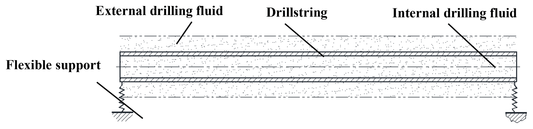
3.1 Model description
The drillstring instinct vibration property was calculated based on finite element analysis software ABAQUS, the simulated pipe model was constructed as shown in Fig. 3. The pipe is with homogeneity, small deformation, and flexible beam, and both ends are supported by springs. Taken the influence of drilling fluid inside and outside into consideration, the mass is distributed on the pipe wall to form interior mass coefficient. According to the pressure effect of outside drill fluid on moving drill pipe, additional mass was reduced, and then exterior mass coefficient was obtained. Submerge condition was added to ABAQUS section characteristic, the drill fluid additional mass effect was considered through lateral additional mass coefficient.
3.2 Interior mass coefficient
In order to consider the influence of interior drilling fluid to the drill string inherent frequency, the model is simplified. The influence of interior drilling fluid to the drill string inherent frequency is mainly on mass effect, the drilling fluid influence reflects to be the equivalent mass change of the drill string participated, that is to say, the drill fluid inside vibration with the drill string, the mass of which is called interior drill fluid additional mass.
Assuming that the length of drillstring is L, and its mass is:
The drill fluid inside drillstring is:
Then the mass of drill sting with inside fluid:
Interior additional mass CN is:
Take formula (18) into formula (17),
Then the interior drill fluid additional mass will be obtained:
In formula (16)–(21), CN is interior drill fluid additional mass coefficient, di is the inside diameter of drillstring, d is outer diameter of drillstring, m1 is drillstring mass, m2 is interior drill fluid mass, ρ1 is drillstring material density, ρ2 is drill fluid density.
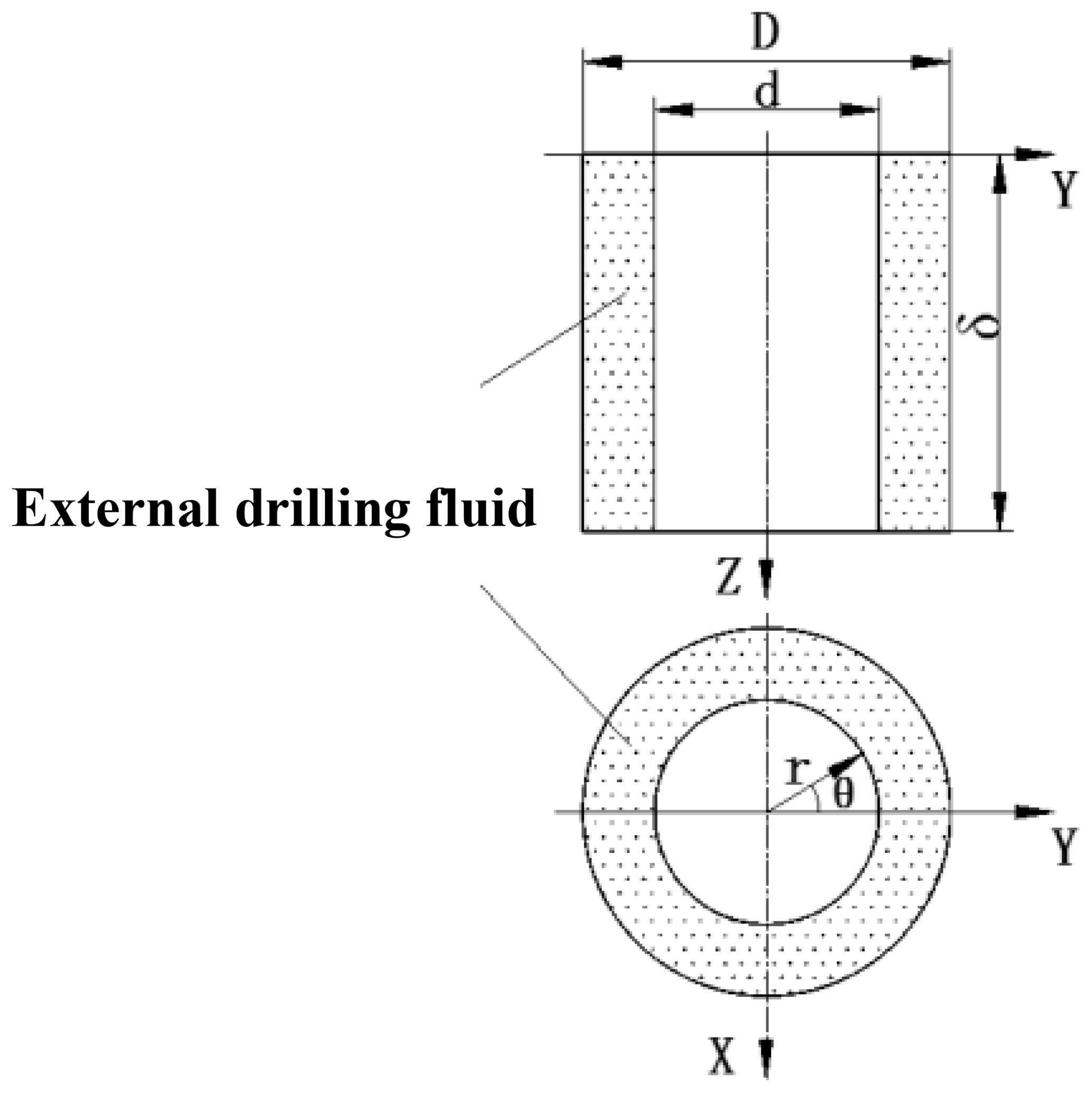
3.3 Exterior mass coefficient
Assuming the outer diameter of the drillstring is d, the inner diameter of the borehole wall is D, set the axial direction of the drillstring is Zdirection, and the model shown in Fig. 4 is established. Set the horizontal movement of the drillstring to make a harmonic vibration along the Y direction, and the displacement of the drill string can be expressed as:
Suppose that fluid media is homogeneous incompressible and perfect, velocity potential function of annulus drilling fluid is:
where, y(z) is the vibration amplitude, φ is velocity potential function, Ψ is amplitude function, ω is drillstring vibration frequency, t is time .
Suppose drill string kinematic equation is y=y(z)eiωt, y(z) is drill string vibration amplitude, could be present as according to variable separation principle, based on hydromechanics fundamental equation,
-
When μ=0, get the following equation:
where, CM is exterior mass coefficient, δ is unite drillstring length, B1, B2 is drillstring axial vibration coefficient.
-
When μ>0,
-
When μ<0,
-
Then, the following equation (Vaz and Patel, 1995) will be obtained:
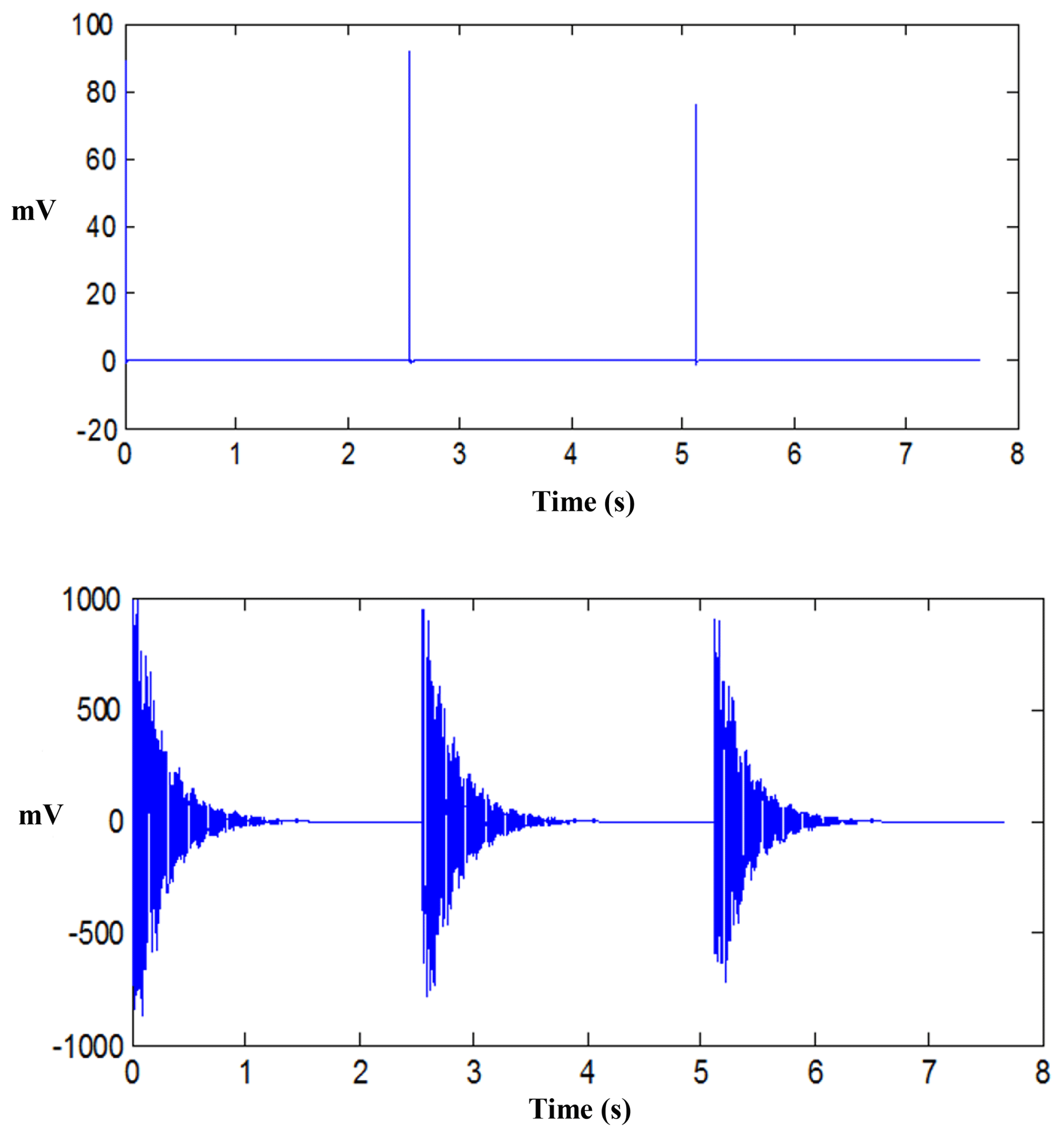
Taking the vibration frequency modal parameter of the experimental drill string (38 mm diameter) in free state as an example, excitation and response signals as show in Fig. 5.
4.1 Frequency response estimation
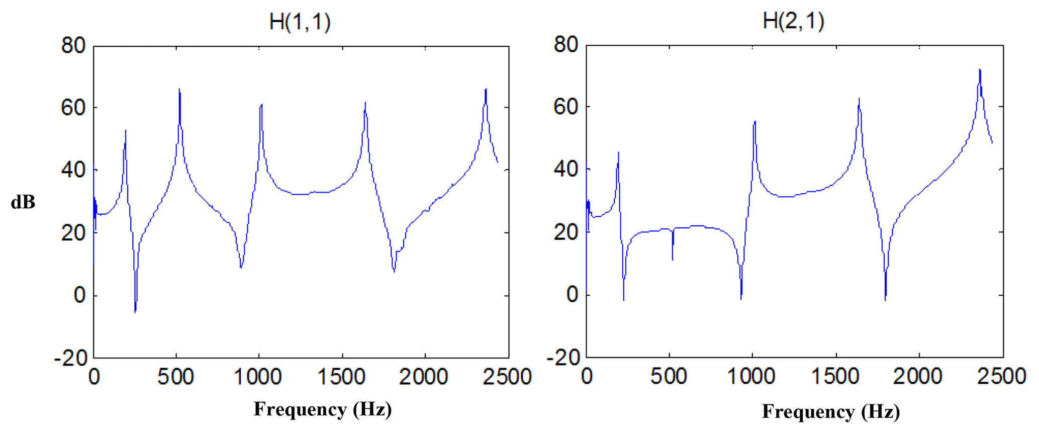
Through the excitation and response signal frequency response function estimation, using H1 estimation, take 3 times average. Typical frequency response signals of measuring point 1 and 2 in the Fig. 2 are shown in Fig. 6.
4.2 Comparative analysis of measurement and simulation results
Analysis of experimental data for 38 mm diameter experimental drillstring vibration frequency in free state. And take the simulation through the finite element analysis software ABAQUS. The modal corresponding to the natural frequency of the corresponding step is obtained, and the simulation results are in good agreement with the experimental results.
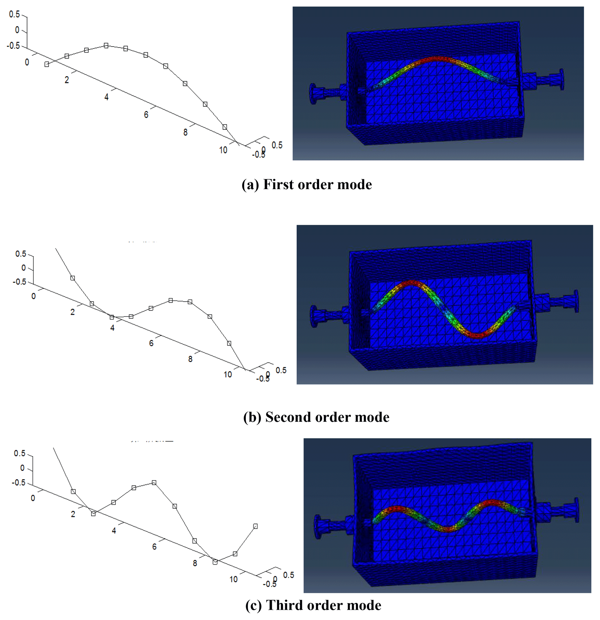
The experimental results show that the first few modes of the 38 mm OD cylindrical tube are shown in Fig. 7 (Left). The corresponding local mode shapes of the 38 mm cylindrical tube simulated by ABAQUS software are shown in Fig. 7 (Right).
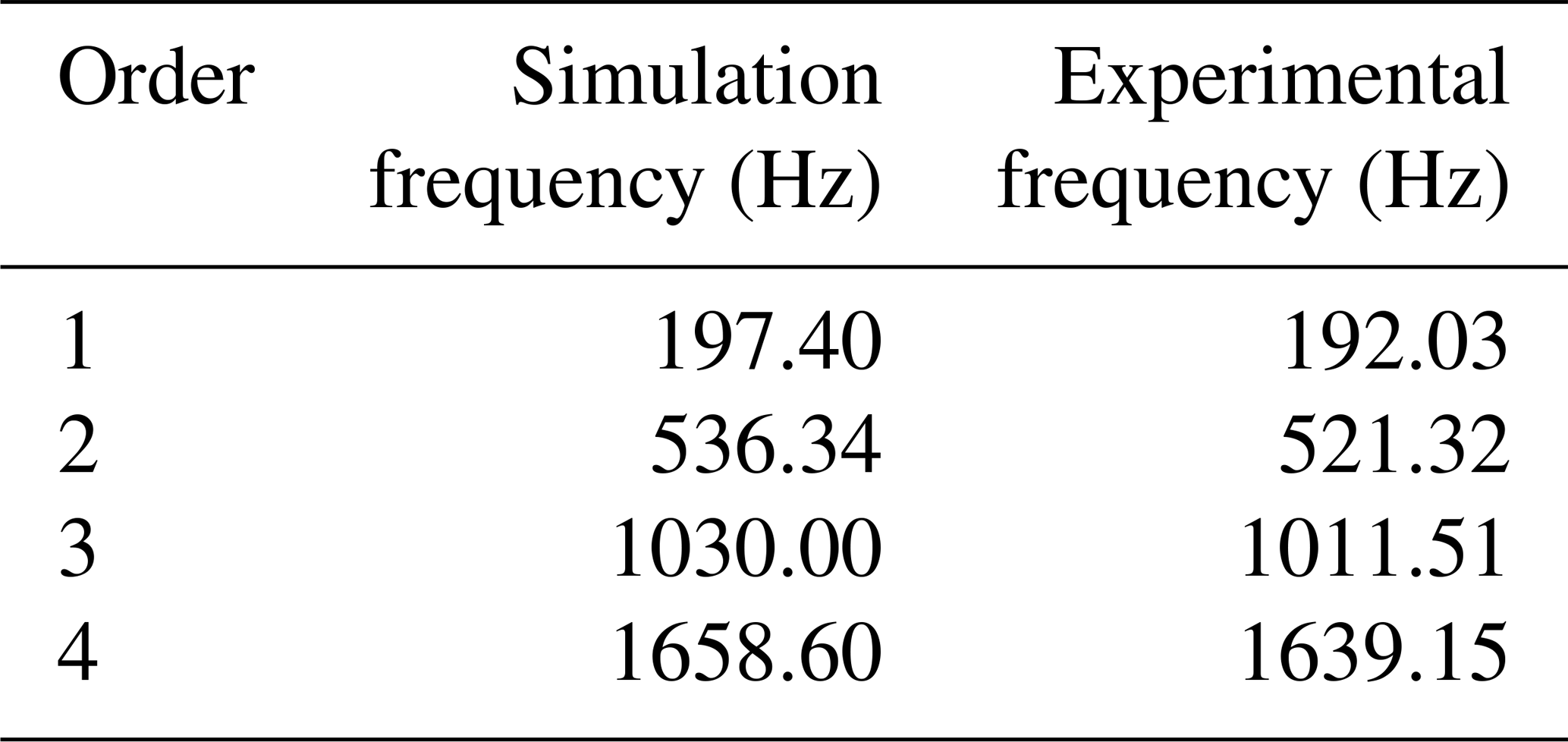
Table 21st order natural frequency of drillstring when the interior is full of liquid.
The calculated value of the natural vibration frequency of the drill string under free state is compared with the experimental value in Table 1, It can be seen that experimental values of the first 4 natural frequencies under the free state of the experimental column correspond well with the calculated values and the relative errors are small (< 2 %), indicating that the calculation method based on ABAQUS software and the experimental measurement procedures and processing software are reliable.
In order to study the effect of drilling fluid to drill string instinct frequency, simulation pipe with OD of 20, 27 and 29 mm, and length of 1.5 m was adopted to compute and calculate. Three conditions, interior filled with drill fluid, or/and submerged in the drill fluid were studied.
4.3 Influence of internal liquid on lateral vibration property
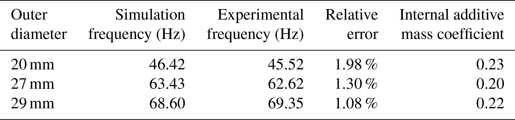
Under the condition that only pipe interior is filled with drill fluid, the hammer strike experiment was conducted of pipe OD of 20, 27 and 29 mm, the pipe instinct frequency was obtained by simulating. According to Eq. (20), the interior mass additional coefficient of each outer diameter was computed, and instinct frequency was calculated through ABAQUS taking its mass effect into consideration. Experimental measurement and simulation results are shown in Table 2.
Table 31st order natural frequency of drillstring when the outside is full of liquid.
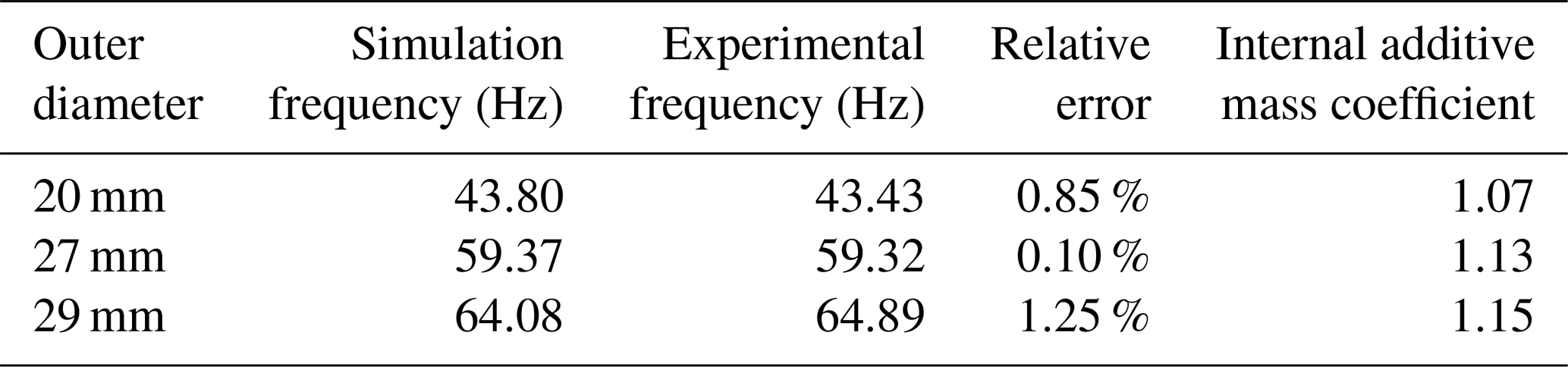
Table 41st order natural frequency of drillstring when the interior and outside is full of liquid.
As can be seen in table 1, as the external diameter increases, the frequency increases. The simulation results are in good agreement with the test results, and the error is within 2 %.
4.4 Influence of outside drill fluid on lateral vibration property
Without consideration of interior drilling fluid, put a lid on both sides of the simulation pipe and then submerge it into a pipe which is filled with drilling fluid, the pipe OD is 110 mm. The hammer strike test were conducted with OD of 20, 27, 29 mm, in order to analyze the instinct frequency. The drilling fluid additional coefficient can be computed according to formula (25), and import the coefficient into software ABAQUS, then the instinct pipe frequency can be computed. Experimental measurement and simulation results are shown in Table 3.
As can be seen from Table 2, as the external diameter increases, the frequency increases. The simulation results are in good agreement with the test results, and the error is within 2 %.
4.5 Influence of drill fluid outside and inside on lateral vibration property
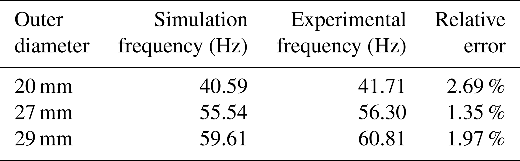
Three pipes are filled with drilling fluid and then are submerged into pipe, which is filled with drilling fluid. The instinct frequency of each pipe can be analyzed through hammer strike experiment. Considering the influence of drilling fluid inside and outside, the drilling fluid additional coefficient are added in the computation. The computation results are listed in Table 4.
In Table 3, both the instinct frequency value of experiment and that of computation are listed, and the difference between them is minor.
According to experiment above, taking the drilling fluid mass effect into consideration, the pipe instinct frequency reduced dramatically. On basis of drilling fluid additional mass coefficient both inside and outside, with use of ABAQUS, it turns out that the difference between computation value and the experiment value is minor. Therefore, the mass effect processing method and the computation method is correct. The computation method can be used in engineering practice.
During the process of drilling, the vibration of drillstring is a widespread phenomenon that has attracted the attention of so many scholars. In this paper, the mass effect of drilling fluid inside and outside on drillstring vibration property was simulated and analyzed, which provide reference to the practical drillstring instinct vibration property. Hammering method is used to measure drillstring lateral natural vibration frequency when the internal and external drilling fluid is considered. The test results show that the drilling fluid can decrease the natural frequency of the drillstring. Based on the finite element method, compared with experimental measurement value, an additional mass coefficient is derived considering the internal drilling fluid. An external drilling fluid additional mass coefficient is derived considering the dynamic pressure effect caused by external drilling fluid. Additional mass coefficient can get the result with high precision, which can meet the needs of the project.
The experiment apparatus was designed taken the influence of drilling fluid inside and outside, an experiment algorithm of measuring influence of drilling fluid was proposed. By utilizing hammer strike to conduct model test on the pipe, and under applying Polymax model analyzing method, lateral vibration frequency under different conditions were obtained. Computing method with drilling fluid additional mass coefficient both inside and outside was proposed. With comparing experiment results with simulation, the accuracy of mass effect handling method and computing method are verified. This work proves the important role of drilling fluid in the vibration analysis of the drill string by provide simulation models and test methods. It also provides a useful attempt and lays the foundation for the dynamics of the drill string in the drilling fluid environment.
The data used to support the findings of this study are included within the article. The data will be available upon request.
CY, RW, LH and QX analyzed the data and developed the model; QX, RW and CY performed the experiments; QX, RW and CY prepared the figures. QX, and CY wrote and edited the manuscript.
The authors declare that they have no conflict of interest.
The author(s) disclosed receipt of the following financial support for the research, authorship, and/or publication of this article: This work was supported by Natural Science Foundation of China (51704264). Key tools and equipment for improving drilling efficiency in complex formations, National science and technology project (2016ZX05021-003).
This research has been supported by the Natural Science Foundation of China (grant no. 51704264) and Key tools and equipment for improving drilling efficiency in complex formations, National science and technology project (grant no. 2016ZX05021-003).
This paper was edited by Guimin Chen and reviewed by two anonymous referees.
Brebbia, C. A. and Wrobel, L. C.: Boundary element method for fluid flow, Adv. Water Resour., 2, 83–89, https://doi.org/10.1016/0309-1708(79)90015-0, 1979.
Bailey, J. J. and Finnie, I.: An analytical study of drillstring vibration, J. Eng. Ind. Trans. ASME, 2, 122–128, https://doi.org/10.1115/1.3663017, 1960.
Chen, S. L. and Géradin, M.: An improved transfer matrix technique as applied to BHA lateral vibration analysis, J. Sound Vib., 185, 93–106, https://doi.org/10.1006/jsvi.1994.0365, 1995.
Christoforou, A. P. and Yigit, A. S.: Dynamic modeling of rotating drillstrings with borehole interactions, J. Sound Vib., 206, 243–260, https://doi.org/10.1006/jsvi.1997.1091, 1997.
Graham, R. D., Frost, M. A., and Wilhoit, Jr. J. C.: Analysis of the motion of deep-water drill strings part 1: forced lateral motion, J. Engin. Ind., 87, 137–144, https://doi.org/10.1115/1.3670778, 1965.
Manolis, G. and Polyzos, D.: Recent advances in boundary element methods, Pentech Press, 71–80, https://doi.org/10.1007/978-1-4020-9710-2, 1978.
Mitchell, R. F. and Allen, M. B.: Lateral Vibration: The key to BHA failure analysis, World Oil, 4, 101–106, https://doi.org/10.1016/0165-1633(85)90018-8, 1985.
Plunkett, R.: Static bending stresses in catenaries and drill strings, J. Engin. Ind., 89, 31–36, https://doi.org/10.1115/1.3610004, 1967.
Sarpkaya, T.: Vortex-induced oscillations (A Selective Review), J. Appl. Mech., 46, 241–258, https://doi.org/10.1115/1.3424537, 1979.
Sarpkaya, T.: A critical review of the intrinsic nature of vortex-induced vibrations vibrations, J. Fluid. Struct., 19, 389–447, https://doi.org/10.1016/j.jfluidstructs.2004.02.005, 2004.
Temple, G. and Gillis, J.: An Introduction to Fluid Dynamics, Phys. Today, 12, 36–38, https://doi.org/10.1063/1.3060769, 1959.
Ritto, T. G. and Escalante, M. R., Sampaio, R., and Rosales, M. B.: Drillstring horizontal dynamics with uncertainty on the frictional force, J. Sound Vib., 332, 145–153, https://doi.org/10.1016/j.jsv.2012.08.007, 2013.
Villaggio, P.: The added mass of a deformable cylinder moving in a liquid, Continuum Mech. Therm., 8, 115–120, https://doi.org/10.1007/BF01184765, 1996.
Vaz, M. A. and Patel, M. H.: Analysis of drill strings in vertical and deviated holes using the Galerkin technique, Engin. Struct., 17, 437–442, https://doi.org/10.1016/0141-0296(95)00098-R, 1995.
Wolf, S. F., Zacksenhouse, M., and Arian, A.: Field measurements of downhole drillstring vibrations, SPE Annual Technical Conference and Exhibition, https://doi.org/10.2118/14330-MS, 1985.
Xue, Q., Leung, H., Wang, R., Liu, B., Huang, L., and Guo, S.: The chaotic dynamics of drilling, Nonlinear Dynam., 83, 1–16, https://doi.org/10.1007/s11071-015-2461-y, 2016.
Xue, Q., Leung, H., Huang, L., Zhang, R., Liu, B., Wang, J., and Li, L.: Modeling of torsional oscillation of drillstring dynamics, Nonlinear Dynam., 96, 267–283, https://doi.org/10.1007/s11071-019-04789-x, 2019.
Yigit, A. S. and Christoforou, A. P.: Coupled torsional and bending vibrations of drillstrings subject to impact with friction, J. Sound Vib., 215, 167–181, https://doi.org/10.1006/jsvi.1998.1617, 1998.
Zamudio, C. A., Tlusty, J. L., and Dareing, D. W.: Self-Excited Vibration in Drillings, SPE Annual Technical Conference and Exhibition, 117–1258, https://doi.org/10.2118/16661-MS, 1987.