the Creative Commons Attribution 4.0 License.
the Creative Commons Attribution 4.0 License.
 | 01 Jul 2019
Designing optimal automatic cycles of round grinding based on the synthesis of digital twin technologies and dynamic programming method
Pavel P. Pereverzev
Aleksandra V. Akintseva
Masar K. Alsigar
Dmitrii V. Ardashev
The article presents methodology for designing optimal feed control cycles resistant to unstable machining conditions for a batch of parts in round grinding operations performed on CNC machines.
To improve the quality and reliability of control programs for CNC machines, a digital twin (DT) is proposed to be used. It performs virtual testing of a given grinding cycle for the possibility of defect occurrence at some combination of variable technological factors. To design the optimal grinding cycle by calculating the optimum trajectory of the radial feed change cycle, we propose the dynamic programming method (DPM) used in solving the classical transport problem, in which a network of roads with intermediate stations is specified. In the task it is necessary to find the optimal trajectory of transport. The conditions for the appearance of defects detected by the DT are introduced into the system of restrictions, and the feed cycle is again optimized in the DPM optimization system. A new optimized cycle is again tested by the DT. These iterations are repeated until the DT fixes the present of a defect for the operation. The methodology proposed in the article for the synthesis of digital twin and DPM technologies at the stage of preparation of control programs for CNC machines makes it possible to guarantee the maximum productivity of the grinding operation while ensuring the specified quality of the machined surface under varying processing conditions that vary within the specified limits.
- Article
(2647 KB) - Full-text XML
- BibTeX
- EndNote


To perform grinding operation, all you need is a control program, which manages the execution of user program to prevent errors and cutting parameters of the automatic steps cycle in CNC programming radial feed. The program feed cycle operates in an automatic mode according to the commands of the active monitoring device and switches the feed-rate depending on the remaining part of the allowance. Designing grinding cycles for control programs is an important stage in the development of the technological process for machining parts in round grinding operations. The quality of their development depends on the performance of the operation, the full application of the technological capabilities of the machine, the amount of defective products.
However, in automated engineering, there are still no CAM-systems which for the given grinding conditions would enable us to calculate the optimal automatic cycle of a step change in feed rate and other operating parameters that provide, in the aggregate, a grinding cycle.
The control parameters and the relationship with the cutting parameters with the productivity of the operation and the quality of the surface to be treated have been studied by Malkin (1981), Fang et al. (2016), Raoufinia et al. (2019). As follows from these works, as well as the works of Uhlmann et al. (2016), Pereira et al. (2009), Liu et al. (2017) and Rowe and Ebbrell (2004), programming the flow parameters of the feed loop is a difficult task, because it is necessary to set the number of stages of the cycle, the feed amount at each stage of the cycle, and the distribution of the allowance along the cycle steps. In addition to step-by-step feed cycles, all other cutting parameters are programmed in the control program which includes the speed of the grinding wheel and the workpiece, the tool characteristics, its overrun and other parameters depending on the type of grinding.
When designing an operation for a CNC machine, the greatest difficulties occur at the stage when the technologist assigns cutting parameters and projects a feed switching cycle, depending on the remaining part of the allowance. In the process of designing the grinding operation, the technologist should strive to design optimal cycle parameters that will ensure the maximum productivity of machining the batch of parts, taking into account the following technological factors and requirements noted in the works of Petrakov and Chamata (2015), Pereverzev and Akintseva (2017), Maris et al. (1975), Lin et al. (2009) and Nathan et al. (2001):
-
requirements for the accuracy of the treated workpiece surface, specified in its drawing;
-
presence of limitations on the parameters of the machine;
-
requirement to ensure the stability of the operation in the presence of variable technological factors that arise when processing a batch of parts: variation in the allowance and the dimensions of the workpiece surface, depending on the initial precision of the billet, the error of basing and setting, etc.;
-
presence of a restriction on the strength of the cutting tool (according to the critical force causing the scattering of the grinding wheel), depending on the characteristics of the grinding wheel.
The analysis of the above-mentioned requirements for designing the mode part of the control program for a CNC machine demonstrates that the task of designing the maximum productive cycle is reduced to the task of designing the optimal grinding cycle in terms of speed, taking into account all the restrictions imposed. Such a problem cannot be solved without using models of the grinding process and mathematical methods for optimizing the cycle.
A literature review surveys books, scientific articles and other sources of relevant information, is refers to many scientists have been engaged in studying the theory of designing optimal grinding cycles for CNC machines of operational performance management, when designing an operation for a CNC machine, the greatest difficulties occur at the stage when the technologist assigns cutting modes and projects a feed switching cycle, depending on the remaining part of the allowance. In the process of designing the grinding operation, the technologist should strive to de-sign optimal cycle parameters that will ensure the maximum productivity of machining the batch of parts, taking into account the following technological factors and requirements noted in the works of Cahill et al. (2015), Lur'e (1979), Pereverzev and Pimenov (2015), Amitay et al. (1989), Phan et al. (2011), Pereverzev and Akintseva (2015), Akintseva and Pereverzev (2017), Alagumurthi et al. (2007), Lee et al. (2006), Krajnik et al. (2008), Bertsekas (1995), Lee (2008), Nishimura et al. (1989), and Hashimoto and Lahoti (2004). However, none of the papers considers the improvement of the design quality of the optimum grinding cycles in terms of their resistance to variable processing conditions existing in real circular grinding operations performed on CNC machines.
Thus, enormous theoretical and practical basis in the design of optimal cycles of round grinding is not sufficient to solve the task of designing optimal grinding cycles which would ensure maximum operation efficiency and stability of meeting the drawing requirements for accuracy and other quality parameters for any most unfavorable combinations of variable grinding conditions.
The aim of the present work is to develop methodology for solving the problem of designing optimal rounds of circular grinding cycles for CNC machines that are optimal in terms of speed and stability.
Let us consider the methodology for designing optimal grinding cycles resistant to variable processing conditions, for example, round grinding with radial feed.
In order to optimize the grinding cycle, we need a model of the allowance removal process first of all during the whole processing cycle, with a stepwise changing feed rate on the commands of the active control device. The model of the removal process of allowance is based on two models: the model of the cutting force and the model of the relationship between the cutting force and elastic deformations of the technological system, with program and actual feeds. Therefore, in the preparation of control programs for CNC machine tools, an analytical model of cutting force is needed to calculate the cutting conditions and grinding cycles in a wide range of various process parameters and processing conditions. Therefore, empirical models that have a number of significant drawbacks cannot be taken as a model of the cutting force, namely: they have a narrowly focused range of application, the coefficients in the empirical formulas are obtained experimentally for the specific conditions of the operation, they do not establish an analytical relationship between the main technological parameters of the process.
A theoretical wide-range model of cutting force which takes into account most of the main technological factors was proposed by Pereverzev and Akintseva (2017), Pereverzev et al. (2015) and Pereverzev and Pimenov (2016). It served as a model of the radial component of the cutting force for circular grinding. The model is obtained by summing the cutting forces of individual grains in the cutting area of the grinding wheel with the workpiece and by applying the principle of equality of the working cutting forces and resistance forces of the processed metal to plastic deformation, formulated by Korchak (1974):
where B – width of the working surface of the wheel, mm; d – diameter of the machined surface, mm; D – diameter of grinding wheel, mm; ndet – rotational speed, RPM; Sf – actual minute feed, mm min−1; V – circumferential speed of rotation of the wheel; i – revolution number of the workpiece; k – radius number in the section of the treated surface; z – radial feed stage number; η – degree of blunting of the grinding wheel; σ – stress intensity in the moving volume of the deformable metal, which characterizes the resistance of the metal to the plastic flow, kg mm−2.
Degree of bluntness of the grinding wheel (η), equals to the ratio of the total area of the blunting areas of all the grains of the grinding wheel on its entire surface to the geometric area of the entire working surface of the grinding wheel (that is, the value of η determines the relative support surface of the grinding wheel along the areas of blunting the grinding wheel grains).
The presented model of cutting force for round external grinding (1) is based on the fundamental laws of the mechanics of metal plastic deformation in the cutting zone, takes into account the kinematics and especially the process of round external grinding, connects the cutting forces with machining modes (radial and axial feedrate, rotational speed of the workpiece and the wheel, etc.), and also covers most of the main technological parameters in a wide range of their variation – physical and mechanical properties of the metal being ground, geometric parameters of the contact area of the grinding wheel and the workpiece, the characteristics of the wheel, bluntings of abrasive grains of the grinding wheel, etc.
To establish the relationship between the cutting force , the elastic deformations with the accumulated program and factual feeds, let us consider the calculation scheme shown in Fig. 1. The diagram shows the graphs and dimensional chains that establish the mathematical relationship between the elastic deformations of the technological system, the accumulated displacements for i of the program and actual feeds with the current actual values feedrate and the current values of the radii of the machined surface at each iturn of the workpiece, for the case when a workpiece having the initial radial run-out is ground ΔRk.
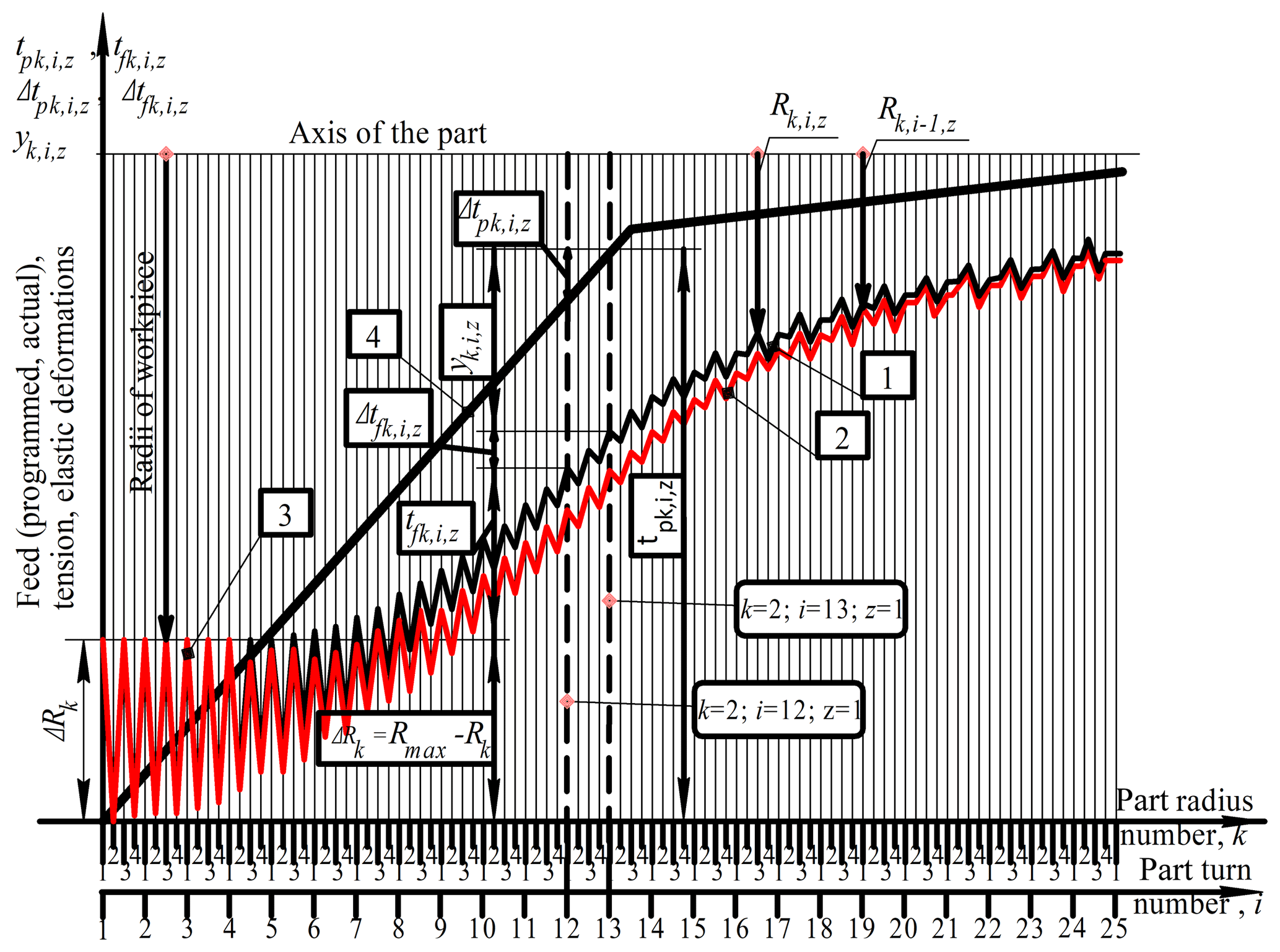
Figure 1Calculation scheme of the relationship between feeds, elastic deformations and current radii at round grinding with radial feed: (1) trajectory of the radius of the part and the actual position i while turning; (2) trajectory of the radius of the part and the actual position i−1 while turning; (3) interrupted cutting zone; (4) programmed feed path.
In Fig. 1, two abscissa-axes are used to synchronize k – the radius number, i – revolution number of the workpiece; and z – stage number of the feed cycle four radius in one stage of the cycle. The actual feed is shown on the graph in the form of two nonlinear trajectories. The lower trajectory reflects the change in the accumulated actual value during (i−1) component revolutions, with being equal to the part of the allowance ground from the kth radius in i−1 revolutions of the part. At the same time, the lower trajectory shows the current value of the kth radius of the part that came from the previous turn.
On the ith turn from the radius the layer of metal , which is equal to the depth of cutting or the value of the actual feed per revolution of the workpiece, will be ground. Therefore, the upper trajectory of the graph shows the change in the value of the part of the allowance ground for i of the component revolutions or accumulated in the actual feedrate per revolution. At the same time, the upper trajectory shows the current change in the radius of the part after the ith turn, i.e.
where ΔRk – initial radial runout of workpiece, mm; – actual feed, mm/revolution; Δtp – programmed feed, mm/double stroke; – radial component of cutting force, kg; – current size of the radius in the section of the machined surface, mm; Rmax – maximum radius of the workpiece, mm; – initial radius of the workpiece on the kth radius, mm; – sum of the actual radial feeds accumulated at each billet radius for all the workpiece turns made, mm; – sum of program feeds accumulated at each billet radius over all perfect double strokes, mm; – elastic deformation of the technological system, mm; γ – compliance of the technological system, mm kg−1.
Solving the set of the obtained Eqs. (1)–(8) with respect to the actual feed-rate we obtain the following formula which makes it possible to calculate current values of the actual feed-rate at each radius and the turn of the balance during the whole grinding cycle.
where K1, K2 – analytical coefficients characterizing the interrelation of various technological parameters of the grinding process.
Substituting the value of the actual feed per revolution into the given above equations, calculated according to Eq. (9), we can calculate the current values of the cutting force, elastic deformation and the radius of the part on each turn during the whole grinding cycle.
Given that the feed per turn is functionally (Eq. 11) related to the minute feed
The graphs of the minute feed for each radius and revolution of the part during the entire grinding cycle, synchronized in time, is shown in Fig. 2.
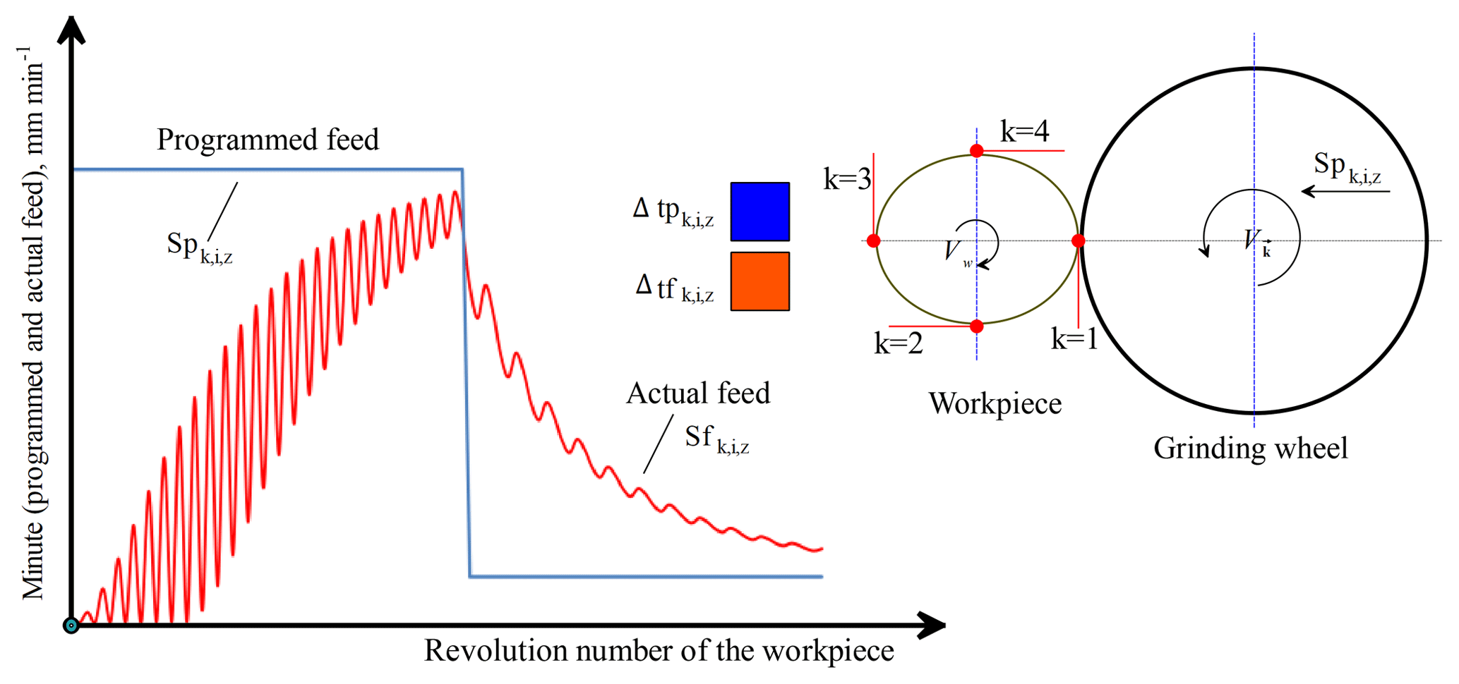
Figure 2The graphs of minute feeds (programmed and actual) in a two-step grinding cycle. Points of actual feed rate are calculated by four radiuses on every round of workpiece
Then, after substituting Eq. (9) into Eq. (11), it is possible to calculate the current minute feed values for each radius and revolution of the part during the entire grinding cycle. The calculation of the grinding cycle time τc is carried out by summing the time of all the revolutions of the part per grinding cycle using Eq. (12)
where Δτz,i – time of one turn of the workpiece.
Thus, the combination of Eqs. (1)–(12) is a wide-range analytical model of the allowance removal process for the operation of circular external grinding with a radial feed that enables the calculation of the current values of all types of feeds, forces, elastic deformations and radii of the surface for any given grinding cycle and processing conditions.
Limitations of models are specifically developed by Pereverzev and Akintseva (2015, 2017), Akintseva and Pereverzev (2017), Bertsekas (1995), Lee (2008) to support objective function of accuracy, roughness and hardness of the treated surface as well as technological limitations on the technical data of the machine and the strength of the grinding wheel.
To calculate the optimal step-by-step grinding cycle, it is necessary to assign optimum minute feed rates for each stage of the cycle and assign the optimum values of the allowance parts taken at each stage of the cycle. According to the active monitoring device, the CNC system switches the cycle stages during grinding. The minimum grinding cycle time is assumed as the target function.
With optimum feed and allowance values at each stage of the cycle, it is necessary to ensure that the cycle will be maximum in speed from all possible cycles and provide a given quality of the treated surface. For this purpose, we developed models of the objective function restrictions for accuracy, non-brushing, roughness of the machined surface, as well as technological limitations on the technical data of the machine and the crumbling of the grinding wheel. These models described by Pereverzev and Akintseva (2015, 2017), and Akintseva and Pereverzev (2017).
This formulation of the problem of calculating the parameters of the grinding cycle is of an optimization nature and requires the choice of a mathematical optimization method.
The analysis of suitable methods described by Pereverzev and Akintseva (2015, 2017), and Akintseva and Pereverzev (2017) showed that the most suitable for optimizing cycles is the dynamic programming method (DPM) developed by Bellman (1960). The optimization of the DPM cycle is carried out by analogy with the optimization of the transport task, in which a network of roads with intermediate stations is specified, it is required to find the optimal transport route between two points A and B. With regard to optimizing the processing cycle, the road diagram is similar to the “grinding process state options” for different feeds when different parts of the allowance are being removed. In our case, the starting point is the initial state of the process (procurement parameters, etc.). The final point is the final state of the process (the parameters of the finished part in accuracy and quality, the main time, etc.). As a result, the problem arises of finding a cycle (the “optimal trajectory of removing the allowance”), which has a minimal basic time among various possible variants of cycles, provided all the technological restrictions are met.
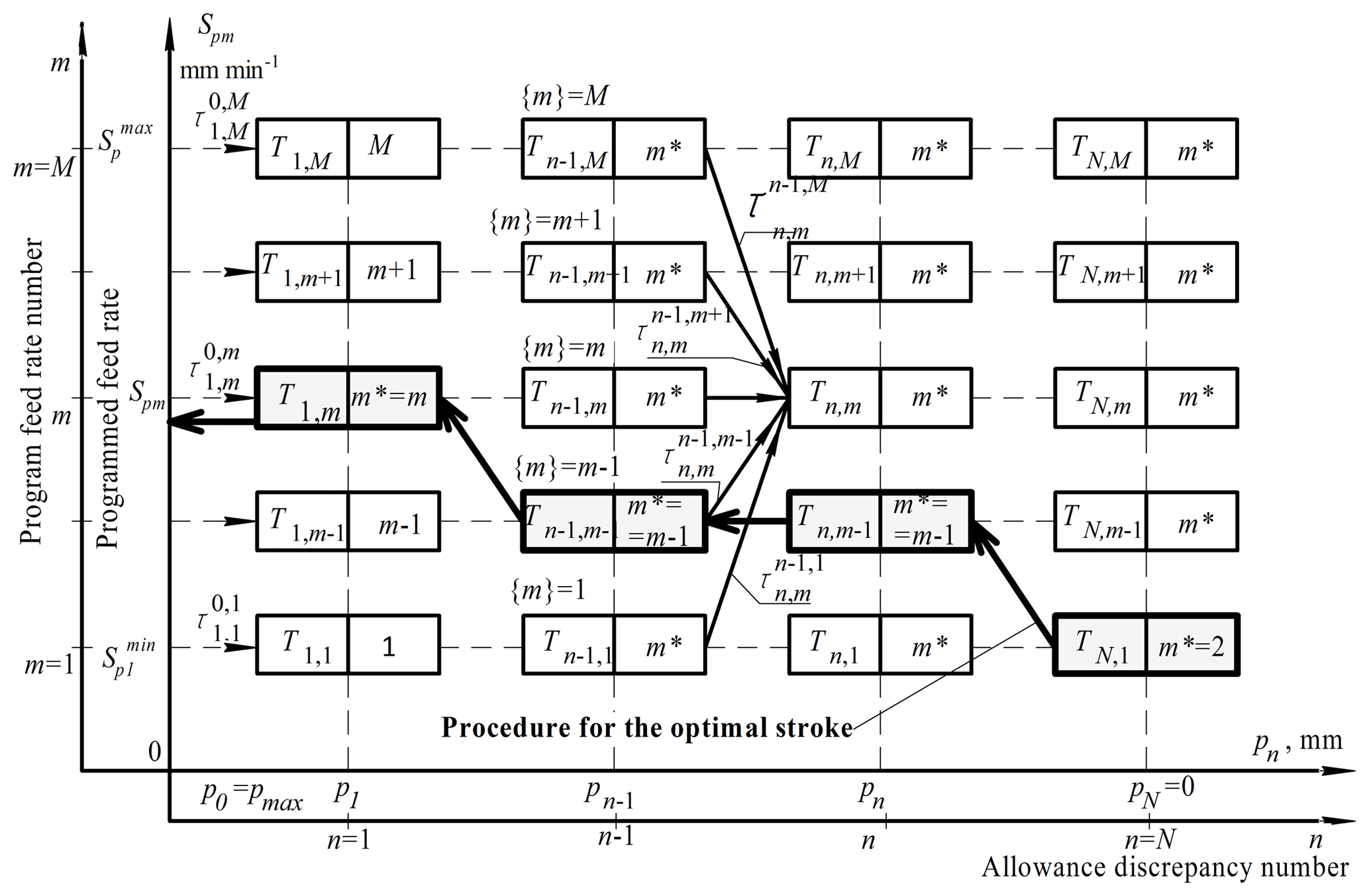
Figure 3Grid for optimizing the grinding cycle (Spm – nominal program minute feed in the DPM optimization system, mm min−1).
When optimizing the grinding cycle with the use of DPM instead of the road network and stations, a coordinate grid with the axes “Program feed Spm” – “Allowance Pn” (Fig. 3) is used. Since the DPM is a discrete optimization method, the feed and overflow axes are divided into small discrete parts. Each intersection of the coordinate grid has an information cell containing the data necessary for the calculation (including the optimal time to reach the state and the coordinates from which the optimum move is made).
Each move is checked for validity of accuracy, roughness and hardness of the treated surface as well as technological limitations on the technical data of the machine and the strength of the grinding wheel. The feed level number m varies in the feed range of the machine from , where M is the maximum feed level (number). The number of the allowance part n varies from , where N is the maximum number of the remaining part of the allowance. Moreover, for n=0 the allowance is maximum, and for n=N the allowance is zero, i.e. allowance was removed completely. The level n=N is the reference point of the removed allowance from the center of the tolerance field of the radius of the part to the maximum value of the radius of the workpiece.
In contrast to the classical transport problem, in which advance time (i.e., time of travel between stations) and permissible strokes is known, then in the optimization of grinding cycles these key values are not known in advance. Therefore, the determination of the travel time (i.e., the removal time of the allowance discrepancy between adjacent grid nodes) is carried out by modulating the removal of the metal, equal to the magnitude of the allowance discrepancy between the coordinates of the nodes of the optimization grid. Simulation is carried out using the removal model of the allowance (1)–(12). In the process of modeling the removal of the part of the allowance, the parameters of the state of the grinding process (yield, cutting depth, cutting force, travel time, surface radius, elastic deformation) are determined. Each stroke is checked for tolerance by four main limitations of the operation: accuracy, roughness, roughness and incidence of the wheel, ensuring the required quality and precision of processing, as well as the main limitations of the technological system (machine drive power and feed ranges).
Admissibility of each move is checked step by step on the principle whether after the next move it is possible to obtain a suitable part with minimum cutting conditions due to the technical capabilities of the machine. If not, the move is considered to be unacceptable.
The method of dynamic programming allows you to organize a direct search of options and avoid a full search. Each station is characterized by two state coordinates, which will be written in the form [n, m].
The process of optimizing the grinding cycle is carried out in full compliance with the DPM. The search of the moves (Fig. 3) is carried out by calculating the time of all admissible moves to the state [n, m] from the previous level [n−1, l], where l – feedrate discrepancy number at n−1 level. In accordance with the MDP procedure, from all competing moves, the optimal move with the minimum optimal time Tn,m was calculated using Eq. (13):
where – time of travel to the state with coordinates [n, m] from the previous level of allowed states [n−1, l] at all values l from 1 till M. on the previous n−1 level, min; Tn,l – optimal time to reach the station at the previous level, min; m – number of programmed supply discrepancies in the DPM optimization system; n – number of the allowance discrepancy in the DPM optimization system. It should be noted that the travel time is the time necessary to remove the part of the allowance between the n−1 and n levels when the program feed is turned on at level m from the process state [n−1, l]. The travel time value is determined by calculation, using the allowance removal model (1)–(12).
After determining the optimal move, the information cell of state [n, m] records the level number from which the optimal move is made. The recording is made in the variable m* and is recorded in the information box together with the value of the optimal time and technological parameters of the grinding process.
A directional search of variants from the calculation of the optimal time values is carried out at all allowance discrepancies.
Thus, the optimization process begins with the execution of the set of straight strokes on the first allowance discrepancy. Then a transition is made from the previous (n−1)th level of allowance, at the mth program feed rate to the nth level of allowance. Each turn is checked for the admissibility according to the given restrictions of the objective function. When the [n, m]th state of the grinding process is reached by one or more permissible moves, the choice of the optimal stroke ensuring the minimum time Tn,m to reach the state [n, m] should be made. The coordinates of the previous state of the process in the variable m* are remembered, the transition is considered optimal. After reaching the last level of allowance n=N (and hence the final state of the process), at the last level of the grid allowance, there may be several cells located at different numbers m of program feed rates and having different time Tn,m. This means that it is possible to obtain a suitable workpiece surface for different values of the actual feed rate at the end of the cycle and the feed rates corresponding to them, but for different processing times. Therefore, out of all available options at the last level of the allowance, we select one having the minimum time TN,M of reaching the final state, which is the minimum time of the τc cycle, i.e.
where τc – grinding cycle time, min;
To fix the optimum control path for the grinding cycle, it is necessary to perform a retraction procedure that starts from this single final state having τc. By analogy with the procedure for the back stroke in the optimization of the route, we determine the previous state of the process , using the stored coordinates of the previous state of the process m*, going from the final level of the allowance to the initial, memorizing the program speeds of the feeds and allowances, after which the program speeds of the feeds were changed by the commands of the active control device.
Figure 2 shows the procedure for the back stroke. In cells on the intersections of the coordinate grid, only numerical values of m* are conditionally given, which is obtained after optimization of the grinding cycle. Empty cells indicate that these intersections have no admissible moves.
The reverse move is made on the basis of the use of the reverse mark m*, which stores the feedrate number, from which the optimal move is made. Using this data, the optimal cycle path is restored, which ensures the minimum cycle time. Therefore, for demonstrating the procedure for the return stroke Fig. 3 presents arrows which in accordance with the value of m* show the coordinate grid node at the previous level, from which the optimal move is made.
Thus, we have developed a method for designing optimal round grinding cycles and makes it possible to calculate optimal radial feed rates at all stages of the cycle and optimal distribution of the removed allowance in the control cycle steps which need the minimum main cycle time of grinding.
The parameters of the grinding cycle on the CNC machine are constant for any variable batch processing conditions: blunting the grinding wheel grains, allowance swing, oscillation of the initial radial runout of the workpiece, size wear of the grinding wheel and reduction of the cutting speed, variable hardness of the technological system in different sections of the surface to be treated, the vibration of the physical and mechanical properties of the material of the part, the variation in the parameters of the characteristics of the grinding wheel, the operation error of the active control device. The number of combinations of variable factors, even for three values of each, is measured in hundreds. But the grinding cycle remains unchanged with any aggregate combination of variable factors, which causes a fluctuation in the accuracy of processing and other quality parameters of the grinding surface.
The optimum grinding cycle, designed on the basis of the average deterministic grinding conditions, has low reliability and stability to the influence of variable technological factors on the accuracy of processing and the provision of other quality parameters. Therefore, the above-mentioned procedure for designing the optimum grinding cycle does not take into account unforeseen situations associated with unstable grinding conditions, blunt grinding of wheel grains, the variation in the allowance or the initial radial runout of the workpiece, etc., which can lead to the appearance of defects in grinding.
To design an optimal grinding cycle that is resistant to the combined effect of various variable technological factors, a system for diagnosing the grinding cycle for stability and the optimal cycle design system is necessary.
When developing a diagnostic system for the stability of the grinding cycle, the concept of a “digital twin” (DT) is applied to the cumulative effect of the constantly changing variables that arise when processing a batch of parts. Within the framework of this concept, a system model DT was designed for: (1) Preventing the defect and the causes of its occurrence in the operation of round grinding; (2) Increasing the reliability and stability of grinding cycle to the combined effect of variable factors; (3) Providing full automation of the design of the control program at the stage of calculation and programming of cutting parameters; (4) Forecasting fluctuations in accuracy, roughness, hardness of the machined surface after machining a batch of parts; (5) Fixing an array of variable factors which caused defects; (6) Forming the array of restrictions of the objective function with variable grinding conditions for the cycle optimization system; (7) Automatic transfer of the array of the objective function restrictions according to the changing grinding conditions in the cycle optimization system; (8) Automatic loading of the tested cycle into the diagnostic system; (9) Automatic completion of grinding cycle diagnostics.
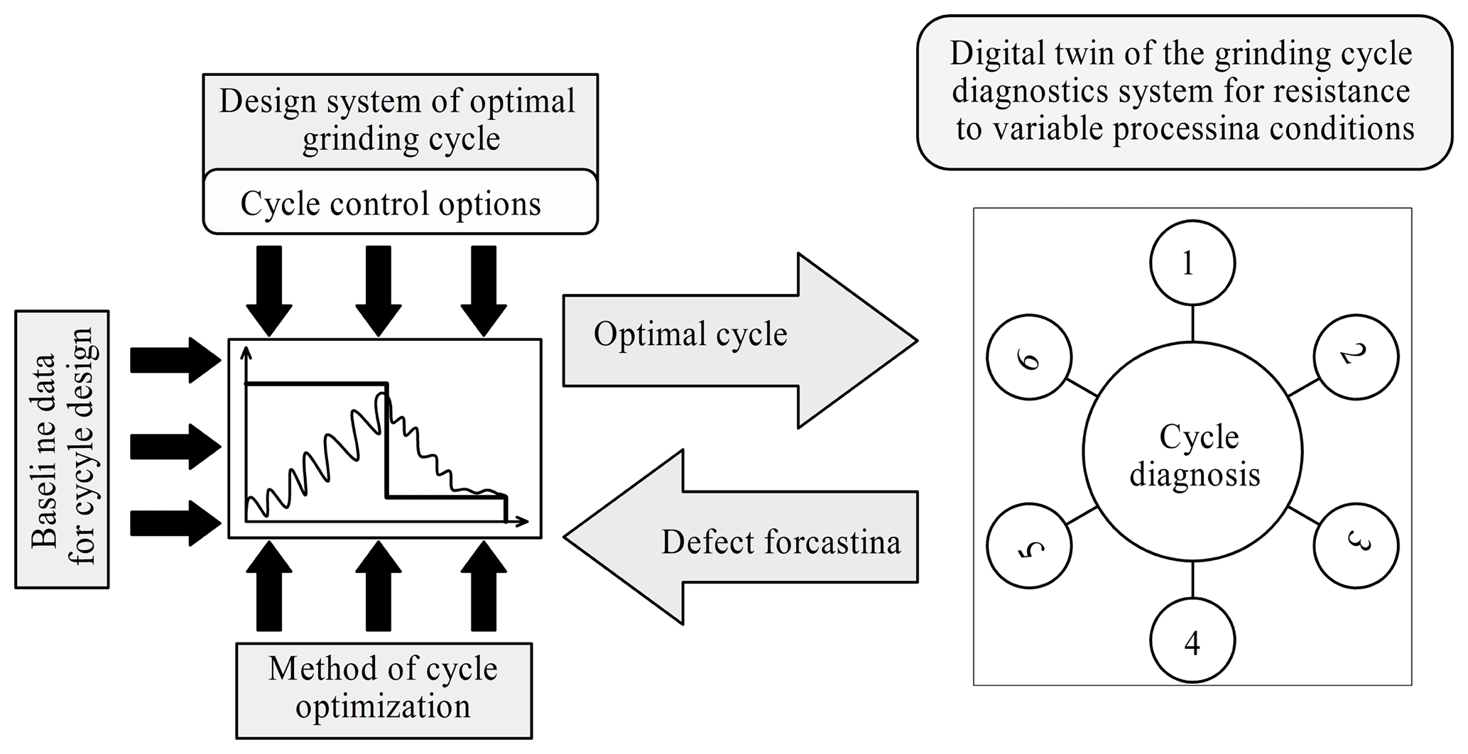
Figure 4Scheme of interaction of the system for optimizing the MDP cycle with the digital twin of the cycle testing system: (1) defect prevention; (2) improving the reliability of the grinding cycle; (3) forecasting the accuracy and quality of processing; (4) formation of restrictions for variable conditions; (5) generation of variable grinding conditions; (6) cycle testing.
The developed system “DT-CicleStab” provides synthesis of diagnostic system and optimization system according to the following algorithm (Fig. 4): (1) The first version of the optimum grinding cycle is designed based on averaged grinding conditions and checking restrictions under these conditions; (2) The optimum grinding cycle is transferred to the cycle diagnostics system; (3) An array of combinations of variable factors is generated; (4) diagnosis of the optimum grinding cycle is carried out for all variants given by an array of variable factors combinations. In the process of diagnostics, the optimal cycle is tested by modeling the grinding process during the whole processing cycle in hundreds of combination variants of variable technological factors (formed in point 3 of the algorithm)which are variable in the given ranges of their variation. After each testing, the estimated values of machining accuracy, roughness, surface hardness and other specified quality parameters are evaluated; (5) All types of defects and the conditions for their occurrence are identified. If there is no defect, this algorithm is implemented; (6) Forming an array of additional restrictions of the objective function on the basis of the revealed conditions for the appearance of defects; (7) Transfer of additional restrictions of the objective function to the system for designing the optimum grinding cycle; (8) Optimization of the grinding cycle with an additional array of the objective function restrictions. A transition is made to point 2 of this algorithm; (9) Forming a report and documentation on the design of the optimum grinding cycle; (10) Transfer of data for the optimum grinding cycle to the control system design for the CNC machine tool. Thus, we have developed a system for designing optimal cycles with improved reliability and resistance to variable grinding conditions.
This article presents experimental studies results to proving the validity and accuracy of the predicted model of cutting forces (1) and removal allowance model (10) in the grinding cycle. Other models have been experimentally proven in the works of Malkin (1981), Rowe and Ebbrell (2004), Petrakov and Chamata (2015), Pereverzev and Akintseva (2017), Lur'e (1979). Several aspects of the models used for this purpose has been developed, based on the prediction of the performance of grinding cycles.
The radial component of the cutting force was adopted as the main object for testing the adequacy of grinding models, because this parameter is the most sensitive one to the action of all technological factors.
Since the grinding process is accompanied by a constant change in the blunting of the grains of the wheel, and the process is non-deterministic in connection with the continuous processes of blunting the grains and tearing them out of the bundle, then the cutting force is also constantly changing. Therefore, in carrying out the experiments, the theoretical value of the cutting force was calculated for the worst processing conditions, corresponding to grinding by a blunt wheel. Thus, the procedure for performing the experiments is as follows: (1) A circular mortise grinding of the sample is carried out according to a given grinding cycle; (2) During the grinding process, the numerical values of the radial component of the cutting force, the actual feed rate and the cycle time are measured and recorded; (3) For a given cycle, a theoretical calculation is made of the variation in the radial component of the cutting force, the actual feed rate and the cycle time, depending on the program feed rates taken in the experiment; (4) The estimation of coincidence of theoretical and experimental values of controlled parameters is made; (5) Experiments are conducted with various combinations of parameters of the grinding wheel characteristics and the processed steel grades; (6) The processing cycle is assigned from the working condition of the grinding wheel in the blunt mode; (7) The allowance for processing is assigned sufficiently large to show different stages of blunting of the grinding wheel grains.
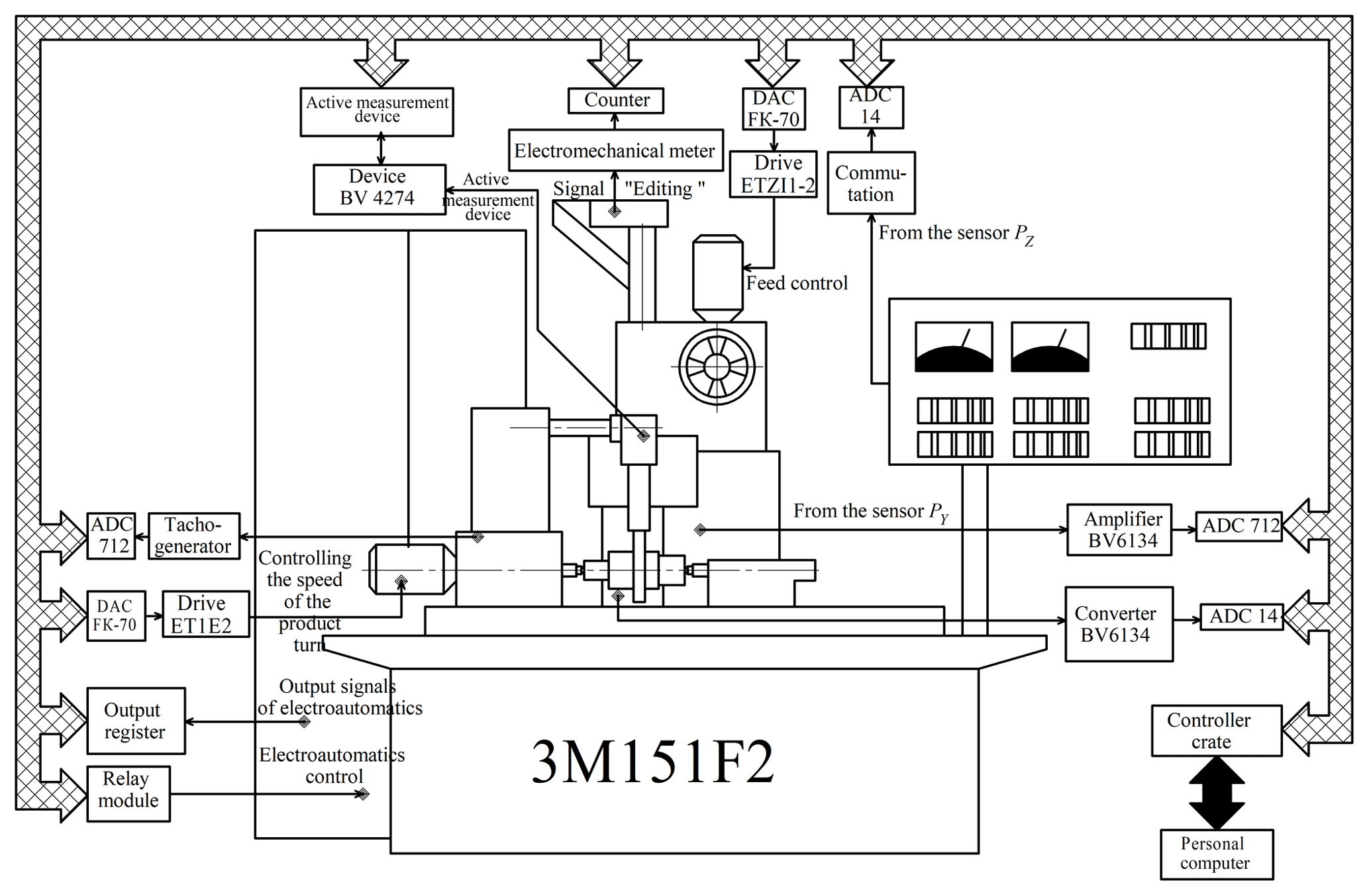
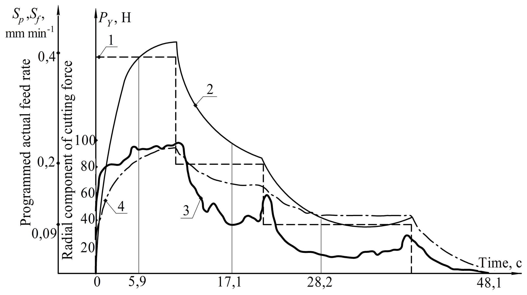
Figure 6Graphs of complex experiment No. 1: (1) experimental graph of the change in the program feed rate in time; (2) experimental graph of the change in the actual speed of delivery in time; (3) experimental graph of the variation of the radial cutting force in time; (4) theoretical graph of the change in the radial component of the cutting force in time.
The experiments were carried out on a measuring and computing stand (MCS) (Fig. 5) created on the basis of a CNC machine of model 3M151F2. The bench is designed for measuring and recording various parameters of the grinding process, entering measurement results in the computer, primary processing, sorting, storage and graphical display of information, automatic adjustment of number of process parameters, program control of processing modes. To perform these functions, the MCS is equipped with number of sensors which together with standard instrumentation are connected to the common computer bus through the modules of the standard CAMAC interface (Fig. 5).
The stand provides two options for measuring the radial cutting force. In the first variant, the measurement is performed using displacement sensors (inductive transducers) mounted in the flange of the bearings of the grinding head spindle. The springs of inductive converters constantly press the levers against the spindle.
Grinding of the samples was carried out with a wheel of at the frequency of the wheel rotation and the sample, respectively, 1480 and 180 rpm. 1 % soda solution was used as a technological liquid. The compliance of the technological system was not changed and according to the measurement results it was 0.0002 mm N−1. The experimental values of the monitored parameters were displayed graphically on the display screen and on the printing device.
Figure 6 shows the results of two experiments in the form of a set of the following graphs visually monitored on the display screen: (1) Experimental graph for changing the program feedrate in time (shown as a step graph); (2) Experimental graph of the change in the actual feed rate in time; (3) Experimental graph of the variation of the radial component of the cutting force in time; (4) Theoretical graph of the change in the value of the radial component of the cutting force. The theoretical calculation of the cycle time differs from the experimental one by 0.1 % … 0.5 %.
The theoretical models of the metal removal process during the grinding cycle are adequate to the results of the experiments, which allowed us to use them in calculating the regulatory and reference database for the design of grinding cycles and the creation of automated cycle design systems.
-
The developed methodology for the design of automatic grinding cycles with optimal parameters of cutting conditions for CNC machines allows to ensure the stable quality of the surface to be processed in terms of accuracy, roughness and hardness, under varying conditions for processing a batch of parts.
-
The methodology of designing optimal cycles is based on the synthesis of:
-
wide-range analytical model of cutting forces;
-
removal allowance model based on the relationship of the elastic deformations of the technological system with the parameters of cutting conditions and processing conditions;
-
Error of processing model can be calculated for given grinding conditions;
-
optimization technique of grinding cycle based on dynamic programming method;
-
stability of Diagnostic and reliability of the grinding cycle to varying conditions;
-
-
results and practical optimization also involves planning to increasing the level of Industrial Automation programming for CNC machines in digital production.
-
The developed model of forming is analytical, due to the fact that it was developed based on mathematical interrelation of cutting force, elastic deformations of a technological system, cutting depth, programmed and actual feeds and treated surface radiuses sizes.
-
The obtained model of allowance removal is a wide-range in terms of variability of technological factors. The model has an analytical character due to the fact that it was obtained on the basis of mathematical interrelation between a radius size of a treated surface and actual feeds with analytical model of cutting force, elaborated on the basis of fundamental mechanics conformity of cutting process and the theory of plastic deformation of metal in a cutting area and which makes a connection with major technological factors, which are:
-
physical and mechanical properties of a grinded metal (stress intensity);
-
geometrical parameters of the contact area of a wheel and a workpiece (actual speed of feed, diameters of a workpiece and a wheel, rotational speed of a workpiece, width of a workpiece treated area);
-
elastic properties of the technological system (elastic deformation and compliance of the technological system);
-
characteristic of a grinding wheel and the grade of wheel grains blunting.
-
-
Interrelation between the model of allowance removal with cutting force gives an opportunity to estimate the influence of different technological factors on productivity, accuracy and quality of processing during variation of the control parameters of the cylindrical exterior grinding cycle. These parameters are cycle stage quantity, program speeds of radial speed on each cycle stage, distribution of allowance on cycle stages.
-
The grinding cycle diagnostics system allows you to design an optimal grinding cycle, ensuring a stable quality of processing a batch of parts.
All data included in this study are available upon request by contacting the corresponding author.
PP has made substantial contributions to the conception and design of the work. AV has made the acquisition, analysis and the interpretation of data for the work. DV has drafted the work or revised it critically for important intellectual content. MA has made a contribution to the acquisition of simulation experimental data and data collation.
The authors declare that they have no conflict of interest.
South Ural State University is grateful for the financial support of the Ministry of Education and Science of the Russian Federation.
This research has been supported by the Ministry of Education and Science of the Russian Federation (grant no. 9.5589.2017/8.9).
This paper was edited by Xichun Luo and reviewed by two anonymous referees.
Akintseva, A. V. and Pereverzev, P. P.: Prospects for the development of the theory of designing optimal cycles of machining in a multidimensional space of control parameters, EDP Sciences, 129, 01018, https://doi.org/10.1051/matecconf/201712901018, 2017.
Alagumurthi, N., Panairadja, K., and Soundararajan, V.: Optimization of grinding process through design of experiment (DOE) – a comparative study, Mater. Manuf. Proc., 21, 19–21, https://doi.org/10.1080/AMP-200060605, 2007.
Amitay, G., Malkin, S., and Koren, Y.: Adaptive control optimization of grinding, J. Eng. Ind., 103, 103–108, 10.31399/asm.hb.v16.a0002175, 1989.
Bellman, R.: Dynamic programming, Foreign Literature Publishing House, Moscow, Russia, 1960.
Bertsekas, D.: Dynamic programming and optimal control, Prentice Hall, Reading, New Jersey, USA, 1995.
Cahill, M. J., Bechtold, M. J., Fess, E., Wolfs, F. L., and Bechtold, R.: Ultrasonic precision optical grinding technology, P. SPIE, 96330, https://doi.org/10.1117/12.2195977, 2015.
Fang, F., Cheng, K., Ding, H., Chen, S., and Zhao, L.: Sustainable design and analysis of CNC machine tools: sustainable design index based approach and its application perspectives, ASME Proceedings, 3, MSEC2016-8730, https://doi.org/10.1115/MSEC2016-8730, 2016.
Hashimoto, F. and Lahoti, G. D.: Optimization of set-up conditions for stability of the centerless grinding process, CIRP Ann.-Manuf. Techn., 53, 1271–274, https://doi.org/10.1016/S0007-8506(07)60696-9, 2004.
Korchak, S. N.: The Productivity of the grinding of steel parts, Mashinostroenie, Moscow, Russia, 1974.
Krajnik, P., Drazumeric, R., Meyer, D., Kopac, J., and Zeppenfeld, C.: Simulation of workpiece forming and centre displacement in plunge centreless grinding, Int. J. Mach. Tool. Manu., 48, 824–831, https://doi.org/10.1016/j.ijmachtools.2007.12.008, 2008.
Lee, C. W.: Dynamic optimization of the grinding process in batch production, J. Manuf. Sci. E.-T. ASME, 131, 485–494, https://doi.org/10.1115/msec_icmp2008-72212, 2008.
Lee, T. S., Ting, T. P., Lin, Y. J., and Htay, T.: A particle swarm approach for grinding process optimization, J. Adv. Manuf. Technol., 33, 1128–1135, https://doi.org/10.1007/s00170-006-0538-y, 2006.
Lin, L., Yong, L., Liwei, W., and Jun, X.: PMAC-based tracking control system for 8-axis automated tape-laying machine, Chinese J. Aeronaut., 22, 558–563, 10.1016/S1000-9361(08)60141-7, 2009.
Liu, Y. M., Yang, T. Y., He, Z., and Li, J. Y.: Analytical modelling of grinding process in rail profile correction cnsidering grinding pattern, Arch Civ. Mech. Eng., 18, 669–678, 10.1016/j.acme.2017.10.009, 2017.
Lur'e, G. B.: Optimizing the grinding cycle by adaptive control, Mashinostroitel, 3, 12–14, 1979.
Malkin, S.: Grinding cycle optimization, CIRP Ann., 30, 223–226, https://doi.org/10.1016/S0007-8506(07)60930-5, 1981.
Maris, M., Snoeys, R., and Peters, J.: Analysis of plunge grinding operations, CIRP Ann., 241, 225–230, https://doi.org/10.1007/978-1-4613-1965-8_6, 1975.
Nathan, R. D., Vijayaraghavan, L., and Krishnamurthy, R.: Intelligent estimation of burning limits to aid in cylindrical grinding cycle planning, Heavy Veh. Syst., 80, 48–59, https://doi.org/10.1504/IJHVS.2001.001154, 2001.
Nishimura, T., Inasaki, I., and Yamamoto, N.: Study on optimization of internal grinding cycle, T. Jpn. Soc. Mech. Eng., 55, 1808–18013, https://doi.org/10.1299/kikaic.55.1808, 1989.
Pereira, W. X., Diniz, A. E., and Hassu, A.: Comparing different plunge cylindrical grinding cycles based on workpiece roughness and process vibration, J. Braz. Soc. Mech. Sci., 31, 161–163, https://doi.org/10.1590/S1678-58782009000200009, 2009.
Pereverzev, P. P. and Akintseva, A. V.: Automatic cycles multiparametric optimization of internal grinding, Elsevier, Procedia Engineer., 129, 121–126, https://doi.org/10.1016/j.proeng.2015.12.019, 2015.
Pereverzev, P. P. and Akintseva A. V.: The problem resolution of designing of cycles in the conditions of modern automated production, Russian Engineering Research, 37, 523–529, https://doi.org/10.3103/S1068798X1706017X, 2017.
Pereverzev, P. P. and Pimenov D. Y.: Optimization of control programs for numerically controlled machine tools by dynamic programming, Russian Engineering Research, 35, 135–142, https://doi.org/10.3103/S1068798X15020197, 2015.
Petrakov, Y. and Chamata, S.: Control of grinding the mandrel working surface of cold-rolling mills, East. Eur. J. Enterpr. Technol., 2, 55–63, https://doi.org/10.15587/1729-4061.2015.39042, 2015.
Pereverzev, P. P. and Pimenov, D. Y.: A grinding force model allowing for dulling of abrasive wheel cutting grains in plunge cylindrical grinding, J Frict. Wear., 37, 60–65, https://doi.org/10.3103/S106836661601013X, 2016.
Pereverzev, P. P., Popova, A. V., and Pimenov, D. Yu.: Relation between the cutting force in internal grinding and the elastic deformation of the technological system, Russian Engineering Research, 35, 215–217, https://doi.org/10.3103/S1068798X15030156, 2015.
Phan, A. M., Summers, M. P., and Parmigiani, J. P.: Optimization device for grinding media performance parameters, Int. Mechan. Eng. Congr. Expos (IMECE), 3, 915–923, https://doi.org/10.1115/IMECE2011-64210, 2011.
Raoufinia, M., Petrakov, Y. V., Ataei, A., Parand, R., and Abou-El-Hossein, K.: Error compensation of complex three-dimensional surfaces machined on computer-numeric-control grinding machine tools, J. Appl. Sci., 9, 1356–1361, https://doi.org/10.3923/jas.2009.1356.1361, 2009.
Rowe, W. B. and Ebbrell, S.: Process requirements for cost-effective precision grinding, CIRP Ann., 53, 255–258, https://doi.org/10.1016/S0007-8506(07)60692-1, 2004.
Uhlmann, E., Koprowski, S., Weingaertner, W. L., and Rolon, D. A.: Modelling and simulation of grinding processes with mounted points: Part I of II – Grinding tool surface characterization, Proc. CIRP, 46, 599–602, https://doi.org/10.1016/j.procir.2016.03.205, 2016.
- Abstract
- Introduction
- Model of the allowance removal process in the operation of round outer grinding with radial feed
- Methodology for calculating optimal feed rates for specified grinding conditions
- Synthesis of the digital twin technology and dynamic programming for testing the grinding cycle for resistance to variable technological factors
- Experimental studies
- Conclusions
- Data availability
- Author contributions
- Competing interests
- Acknowledgements
- Financial support
- Review statement
- References