the Creative Commons Attribution 4.0 License.
the Creative Commons Attribution 4.0 License.
 | 11 Jun 2019
Analytical Study of Babbitt/steel Composite Structural Bars in Oblique Contact-impact with a Solid Flat Surface
Zhuang Fu
The oblique contact-impact characteristic of the composite structural bar composed of Babbitt alloy and low-carbon steel (ZChSbSb11-6 ∕ AISI 1020) with a solid flat surface (AISI 1045) was studied theoretically and experimentally. The dynamic equation of the composite structural bar with vibration response during the contact-impact was established using the momentum theorem and assumed mode method, and the instantaneous contact forces during different impact phases were analyzed based on modified Jackson–Green model. Four sets of experiments (i.e. different proportion of Babbitt, ) for the initial angle, , and different initial velocities were performed; and, the rebound linear and angular velocity of the contact point of composite structural bar after impact was calculated and compared with experimental results. Besides, the coefficient of restitution, the relation of contact force and contact deflection, and the permanent deformation were also compared for the composite structural bars with different proportions in combination, ξ. Three critical angles are found to determine whether the composite bar slides or not, but are prominently different for the composite bars with different ξ. In comparing with the experimental results, the numerical solutions of rebound linear and angular velocity had yield encourage results and, all relative errors were small, indicating that the simulations are in good agreement with the experimental results. Also, the oblique contact-impact behavior involving the coefficient of restitution, the relation of contact force and contact deflection, and the permanent deformation was explained in detail. It can be concluded that as the proportion of Babbitt ξ increases, the composite structural bar presents a characteristic of ease of deflection. And the contact-impact behavior of structural entity is closely related to the inherent properties of the elasto-plastic material, especially for the weak material of composite structures. The more easily the impacting object is deformed, the small the contact force during the contact-impact, which also indicates the yield strength of weak material is a very significant parameter in the event of collision. Such work could give conducive insights to contact-impact problems of the key parts or structures composed of composite materials in mechanical system.
- Article
(8341 KB) - Full-text XML
- BibTeX
- EndNote


Contact-impact is a particularly salient phenomenon which plays an important role pervasive in many applications involving the design and analysis of mechanical system, such as robotics (Banerjee et al., 2017; Flores-Abad et al., 2014), iron and steel metallurgy (Y. Wang, et al., 2017a), vehicles (Yuan et al., 2016), civil structures (H. Wang, et al., 2017a), composite structures (Mao et al., 2017; Park, 2017), and many other fields (Brake, 2015), since it affects motion parameters of the impacting object (e.g. rebound linear and angular velocity), contact force, and indentation deformation involving its patterns etc (Dong et al., 2018; Ghaednia et al., 2017b). Various normal and oblique impact events happening on the surface of two or more colliding bodies had been studied by many researches for decades. For any contact-impact events, authors focus primarily on what happened during the impacts and/or after the impacts (Meng and Wang, 2018). On one hand, the behavior of the impacting object such as bar, rod, or sphere during the impact is hard experimentally to measure, since the impact occurs in a very shot time and involves large contact force and changes in velocity of the colliding bodies. On the other hand, to find the relation of contact force and contact indentation and, simulate and predict the motion of the impacting object will continue remain relevant challenges in contact-impact. Additionally, the difference of impact response for different shapes or material properties is very obvious (Y. Wang et al., 2017a), especially for composite materials withstanding high impact load, i.e., contact force (Xie et al., 2016; Zhikharev and Sapozhnikov, 2017). Numerous studies reported in literature indicated that composite materials are widely used as structural materials in various fields, such as aerospace, military, as well as in nuclear power due to their characteristics of higher strength and stiffness, compared with general metallic materials (Appleby-Thomas et al., 2015; Boroujerdy and Kiani, 2016; Li et al., 2016). However, in engineering practice, heavy loads and/or impact loads with uncertainty are easily to induce varying levels of internal damage, which can also result in significant degradation of the structural strength. Thus, more and more investigators and scholars pay close attention to the contact-impact problems and its effect on the performance as the key parts or structures are increasingly made of composite materials.
For the bearing bushing of oil-film bearing as the key load-carrying component, it is usually a composite structure composed of Babbitt and steel, and which is most commonly prepared by casting or spraying process (Babu et al., 2015; J. M. Wang et al., 2017; Zhang et al., 2015). Especially, the impact damage is a ubiquitous phenomenon during the operation of oil-film bearing, and composite structures (i.e. Babbitt layer and steel substrate) with different proportion in combination have significant differences in their bonding strength (Li et al., 2016; Wang et al., 2015; Y. Wang, et al., 2017b). So, a systematic study on the contact-impact behavior of ZChSbSb11-6 Babbitt/20 steel composites is required to establish a suitable dynamic analysis model in order to ensure the reliability, safety, and service life of the product.
To the best of our knowledge, although a great deal of research and publications concerning the fully elastic or elasto-plastic contact-impact problems have been carried out on the contact/impact models in order to represent the complicated contact-impact behaviors – such as coefficient of restitution (Christoforou and Yigit, 2017; Khulief, 2013; Wang et al., 2019), permanent deformation (Ghaednia et al., 2015b, 2017a; H. Wang, et al., 2017b; Y. Wang, et al., 2017a), and the analytical relation of contact force-indentation (Bartier et al., 2010; Brake, 2012; Ghaednia et al., 2016) – of the impacting or colliding objects, those contact models for impact events can be divided into two major categories: flattening and indentation models (Ghaednia et al., 2015a). For the indentation models, such as Kogut–Komvopoulos model (Kogut and Komvopoulos, 2004), Ye–Komvopoulos model (Ye and Komvopoulos, 2003), and Brake model (Brake, 2012; Brake, 2015), the impacting object is considered to be rigid and the flat surface deforms. On the contrary, for the flattening model, such as Vu–Quoc model (Vu-Quoc et al., 2000), Kugut–Etsion model (Kogut and Etsion, 2002), and Jackson–Green model (Jackson and Green, 2006), the flat surface is assumed to be rigid and the impacting object deforms. Besides, there are a few models such as Gheadnia model (Gheadnia et al., 2015a, 2017b) and Ma–Liu model (Ma and Liu, 2015), in which they assume both objects deform; and, there are many visco-elasto-plastic models such as Hunt–Crossley model (Hunt and Crossley, 1975) and Christoforou–Yigit model (Christoforou and Yigit, 2017), that are widely used to study elasto-plastic impact issues using damping. On the whole, these previously mentioned models divide the contact-impact events into two main phases: the loading and unloading phase, where only different description of sub-phases are used for the loading phase depending on different contact models (Meng and Wang, 2019). Some models (e.g. Jackson–Green and Kogut–Etsion models) divide the loading phase into two sub-phases: the fully elastic and the elasto-plastic phases; and, the loading phase of another model (e.g. Brake model) consists of three sub-phases: the fully elastic, the elasto-plastic, and the fully plastic phase. Obviously, the fully plastic regime is the one limit of the elastic-plastic phase. For the unloading phase, it refers to the restitution phase. Inspired by these analytical contact-impact models, more efforts on the application of composite structures will still need to be taken on the oblique contact-impact behavior, where different proportions of each material constituting the composite structure should be considered.
In our previous work, we studied the mechanical properties of the ZChSbSb11-6 Babbitt/20 steel composites with different proportions of Babbitt, and found that the elastic modulus of composite varies with different proportions of Babbitt based on the experimental results (Li et al., 2016). In Y. Wang, et al. (2017a), the relationships of coefficient of restitution, permanent deformation, and initial impact velocity during normal impacts were analyzed; and, the constitutive behavior between the contact force and the contact deflection (i.e. indentation deformation) was also studied using the established indentation contact-impact model based on the empirical formulation developed by Brake (2015). Similarly, each contact-impact event is divided into three phases: the elastic, the elasto-plastic, and the restitution phase. In the present work, we focus on modeling and simulating the oblique elasto-plastic impact for composite bars using the modified Jackson–Green model (Ghaednia et al., 2015a, 2017b), and performing the experiments from different heights (or initial impact velocities) for the initial impact angle . Contact-impact behaviors – rebound velocity, coefficient of restitution, analytical relation of contact force and contact deflection, and permanent deformation – of the ZChSbSb11-6 Babbitt/20 steel composites with different proportions of Babbitt are also presented, and the whole work is driven by the goal to get a more complete understanding of the mechanics property for the composite structures during contact-impact events.
The layout of this work is that, in Sect. 2, the mathematical models are established for the oblique contact-impact of composite structural bars with a solid flat surface, consisting of the dynamic model with vibration response and the elastic-plastic model of contact force during each impact phase; in Sect. 3, the specimens used, the experimental methodology, and the experimental data processing are presented; in Sect. 4, some comparison analysis between the simulations and the experimental results are performed; some conclusions are drawn which are useful for the performance evaluation of composite structures in elasto-plastic oblique contact-impact events.
As illustrated in Fig. 1, a composite structural bar B with a length L impacts a solid flat surface S. The composite bar is made of Babbitt layer (Tin-based Babbitt, ZChSbSb11-6) and steel substrate (20 steel) as shown in Fig. 1a, and the solid flat surface is made of 45 steel. A global reference frame RF(0) of Cartesian unit vectors [i0, j0, k0] and a mobile reference frame RF(1) of Cartesian unit vectors [i1, j1, k1] are considered as shown in Fig. 1b.
The initial impact angle is θ. The center of the mass of the composite bar is point C, the contact point is at E, and the top point is A. The gravitational force is G and the contact force during the impact is F. Generalized coordinates q1 , q2 , q3 are employed to characterize the instantaneous configuration of top point A of the composite bar B in RF(0). The first generalized coordinate q1 denotes the distance from A to the vertical axis of RF(0) and the second generalized coordinate q2 denotes the distance from A to the horizontal axis of RF(0). The third generalized coordinate q3 designates the initial impact angle θ. To characterize the motion of B in RF(0), the corresponding generalized speeds defined as (where ), represent the rate of change of the generalized coordinates with respect to time t.
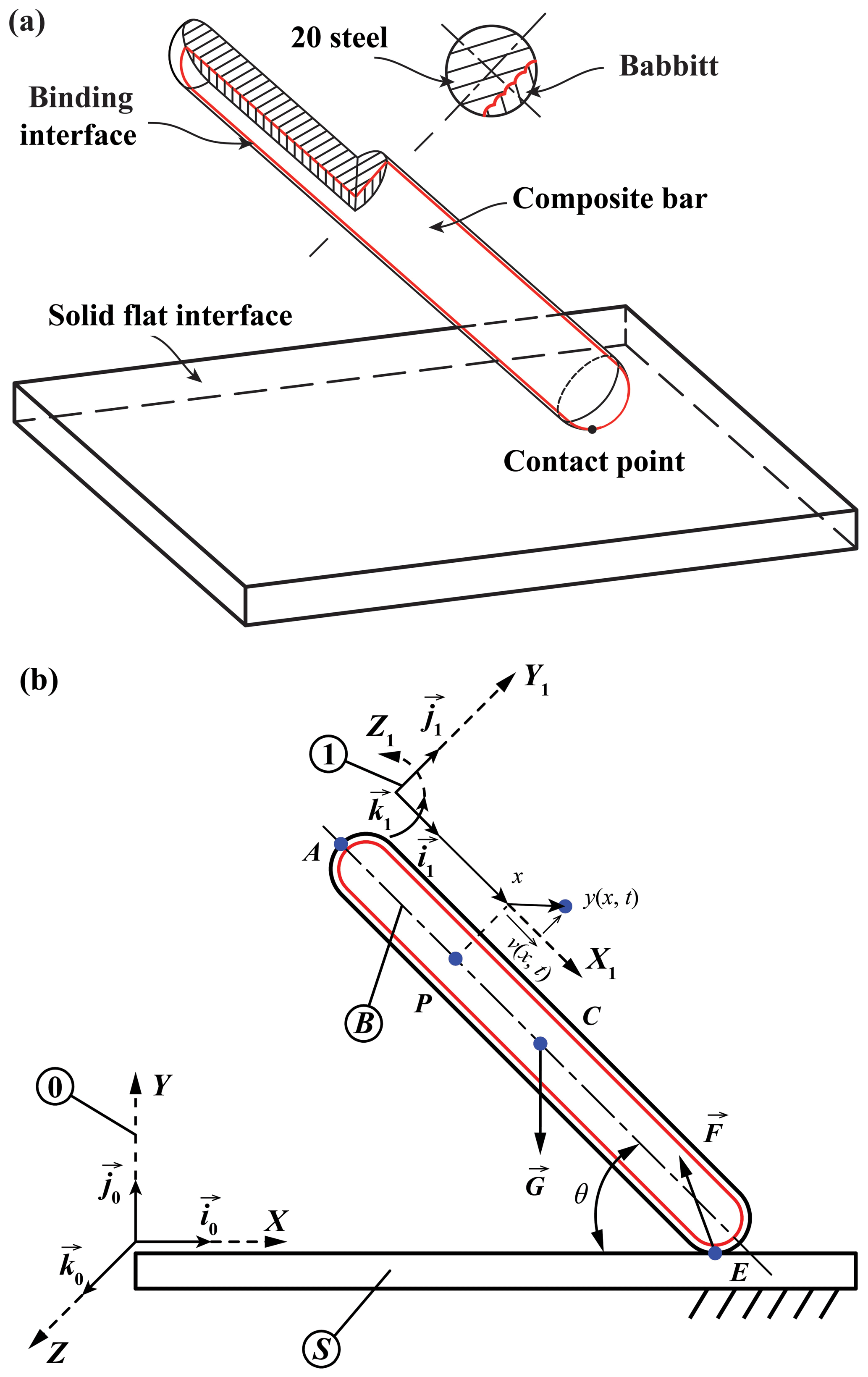
Figure 1Schematic of the composite structural bar during a contact-impact event: (a) the 3-D view, and (b) the kinematic chain.
2.1 Elastic modulus of the composite bar
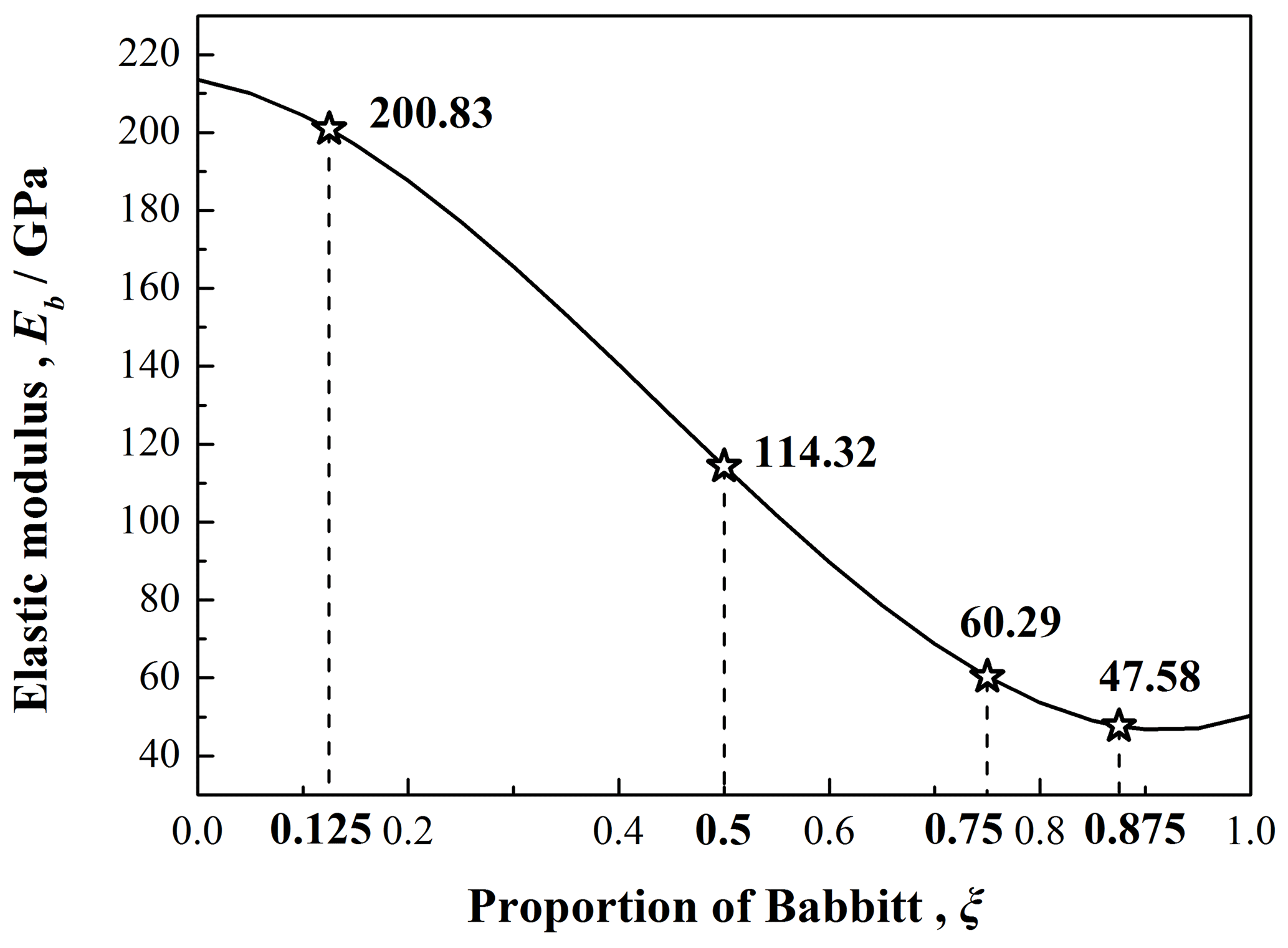
For the elastic modulus Eb of composite bars with different proportion of Babbitt ξ, the experimental results in Li et al. (2016) has been used as shown in Fig. 2. In Fig. 2, the elastic modulus (Eb) of composite bars decreases monotonically with the increasing proportion of Babbitt (ξ), and the pentagram points represent the elastic modulus of specimens used in our experiments (as seen in Sect. 3.1).
The mathematical expression for the elastic modulus (Eb) depending on proportion of Babbitt (ξ) provided in Li et al. (2016) is as below:
with
where ξ represents the proportion of Babbitt, Ab is the cross-section area (as shown in Fig. 1a) of the composite bar, and ABabbitt is the area of Babbitt.
2.2 Dynamic model with vibration response
Published amounts of research indicated that the effect of longitudinal and/or transverse vibration response during the motion and dynamic modeling can not be neglected for the elasto-plastic contact-impact events (Bazrafshan et al., 2014; Shafei et al., 2018). Authors previous works had done a quantitative analysis for mechanical vibration of the impacting object during impact events, and the longitudinal and transverse vibration responses were found to effect the normal and tangential velocities of the contact point after the impact, respectively. Besides, for the oblique contact-impact with sliding, considering the response of longitudinal and transverse vibration at the same time was more reasonable than other cases, such as only longitudinal or transverse vibration. But, increasing the number of shape functions did not effect the result significantly (Meng and Wang, 2018; Wang et al., 2019). Thus, vibration response with two shape functions is considered in the deformation of the contact point. In what follows, the equations of motion of a composite structural bar with a solid flat surface during the oblique contact-impact events were developed using the momentum theorem and assumed mode method.
The unit vectors of the reference frames can be expressed as:
where R10 represents the transformation matrix
and s3=sin q3, c3=cos q3.
The angular velocity and acceleration of the composite bar B are:
The position and the velocity vector of the point A are:
As previously mentioned above, longitudinal and/or transverse vibration of the composite bar B during the contact-impact events will be considered in the deformation of contact point. Using the assumed mode method, the longitudinal elastic displacement ν of an arbitrary point P on the composite bar in RF(1) can be expressed as:
with the longitudinal shape modes are:
where n represents the number of vibrational modes selected, Φi(x) is the mode shape of a composite bar with both ends free and qi(t) is the elastic generalized coordinate.
Similarly, the transverse elastic displacement y of an arbitrary point P on the composite bar in RF(1) can be expressed as:
with the shape modes for transverse vibration are:
and
where represents the mode shape of a composite bar with both ends free, and λi is the consecutive root of the characteristic equation.
So, for any point P of the composite bar, the vector rAP can be expressed in terms of the mobile reference frame RF(1) as:
In the global reference frame (0), the position vector rAP can be written as:
The velocity of any point P of the composite bar B has the following expression in the reference frame (0):
The kinetic energy of the composite bar, T is calculated as follows:
where ρ is mass per unit length.
Assume that the duration of the system involved in an contact-impact event is [t1, t2]. Using the momentum theorem, the generalized momentum and impulse equations for the impact of a composite bar B with a solid flat surface S are found after the integration of Kane's equations (Kane and Levinson, 1985) which yields,
where Pj is the generalized impulse, Mj is the generalized moment, and j represents the jth generalized speeds.
The kinetic energy in (0) is a function of , and t. The generalized moment Mj can be calculated as:
where k is the number of generalized speeds. The generalized impulse Pj is calculated as:
where is the partial velocity at any time.
Substituting Eqs. (16) and (17) into Eq. (15) yields the equation for the oblique contact-impact:
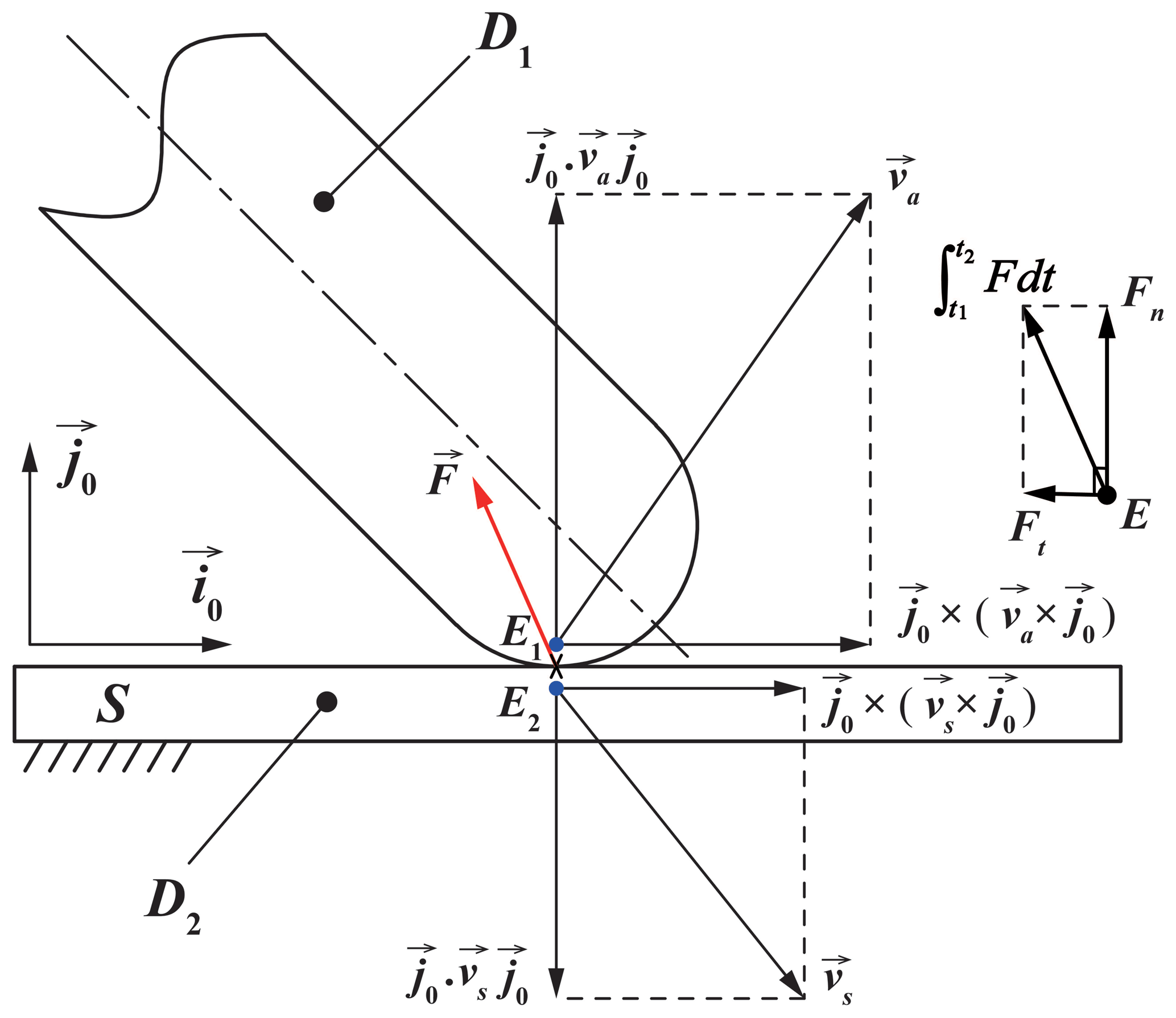
To describe the motion of the system at t2, more information must be added to Eq. (18). Figure 3 shows the graphic of the velocity vector for two bodies during the contact-impact events. The bodies D1 and D2 impact each other and their contact points are E1 and E2, respectively. The velocity of approach va is:
where and are the velocities of points E1 and E2 at time t1, respectively. The velocity of separation vs is:
where and are the velocities of points E1 and E2 at time t2, respectively.
As shown in Fig. 3, the contact force exerted on D1 by D2 at the contact point E during the contact-impact, F, is integrated with respect to t from t1 to t2 and resolved into two mutually perpendicular components, normal impulse, Fn and tangential impulse, Ft. The normal components of va and vs have opposite directions, and the relation between their magnitudes is based on the definition of the coefficient of restitution e:
A condition, Δ, is used to find the type of the friction for the contact-impact of the composite structural bar B on a solid flat surface S, which can be estimated by the formula as below:
where μs is the coefficient of static friction between a composite bar and a flat surface.
When Δ<0, the tangential component of vs must be zero which means:
Thus, no sliding occurs for this condition. Adding Eqs. (21) and (23) into Eq. (18) yields the motion of the composite bar during the contact-impact with all unknowns.
When Δ>0, the composite bar slides during the impact, and the following relation must be satisfied:
where μk is the coefficient of kinetic friction between a composite bar and a flat surface.
In this case, the kinetic of the composite bar with all unknowns can be calculated by adding Eqs. (21) and (24) into Eq. (18). MATLAB has been used to find and solve the above equations of motion. Because the impulse is the cumulative effect of contact force on time and is a process quantity, the instantaneous contact force during the contact-impact can not be obtained, and further studies are needed to characterize the relation of contact force and contact deflection.
2.3 Contact force analysis
Based on flattening model, i.e., modified Jackson–Green model provided in Gheadnia et al. (2015a, 2017b), the contact-impact process of the composite bar with a solid flat surface is divided into three phases: the elastic, the elasto-plastic, and the restitution phase. In what follows, the instantaneous contact forces during different impact phases are analyzed.
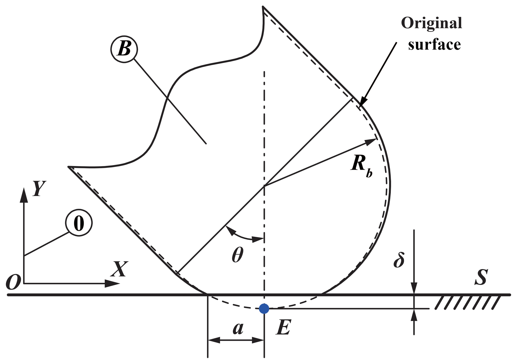
Figure 4 shows the schematic of contact deflection during impact events. The contact-impact process can be described as follows. When the rounded end of one impacting object (i.e. the composite structural bar) is brought into contact with the solid flat surface, the elastic phase starts and continues until yielding of weak material occurs; then, the elasto-plastic phase starts and continues until the contact point E of the impacting object stops (i.e. the normal velocity of the contact point is zero at this moment). That is to say, the indentation of the contact point E into the solid flat surface reaches the maximum deformation. At this point, the elasto-plastic phase comes to an end and the restitution phase starts. The restitution phase continues until the contact force reaches zero (i.e. there is no contact at this point), and at this instance the deformed region reaches the permanent deformation.
Using the methodology originated from Hertzian theory of the contact, the contact force for the elastic phase of the contact, Fe, is calculated as follows:
with
and
where R is the reduced radius (Note that R=Rb for our case since Rf=∞), E′ is the reduced modulus of elasticity, the contact deflection is δ, yE is the y coordinate of the contact point E in (0), and Eb, μ1 and Ef, μ2 are the elastic modulus and Poisson's ratio of the two materials in contact (B and S) respectively.
According to Gheadnia et al. (2015a, 2017b), the effective elasto-plastic phase starts at , which also means the elastic phase will end when the critical point of the elastic phase is , and will provide the initial conditions for the next phase, where , and Cj=1.295e0.736μ.
For the elasto-plastic phase, the expression of contact force, Fp, is shown as below:
where Fc is the critical force at the instant the yield occurs, HG is the average normal pressure, the real contact radius is a, and δc is the critical deformation, with
For the restitution phase, it has also been assumed to follow the Hertzian theory. So, the contact force for restitution phase, Fr, is calculated as follows:
where Rr is the new radius of curvature, and δr is the permanent deformation. Then,
where δm is the maximum deformation when the normal velocity of the contact point E of the composite bar is zero, and δy is indentation at which yield starts. From continuity, the new radius of the curvature Rr in this phase is changing as below:
where Fm is the maximum contact force corresponding to the maximum deformation δm.
The oblique contact-impact events were performed by dropping the composite structural bar (B) from different initial heights (i.e. initial impact velocities) with an initial impact angle θ on a solid flat surface (S). A 3-D high-speed camera was adopted to capture the kinematic data of the markers on the composite structural bar during contact-impact events. Four sets of experiments (i.e. ) for the initial angle, , and different initial velocities have been completed. Each height was tested at least three times in order to achieve stable experimental data.
Figure 5Shape and dimension of specimens for contact-impact testing, with different values of h described in Table 1.
A rounded ended composite bar B was composed of ZChSbSb11-6 Babbitt and 20 steel (i.e. Babbitt layer and steel substrate) with length L, diameter d, elastic modulus Eb, and yield strength of . The solid flat surface S is made of 45 steel with length Lf, width Wf, thickness Tf, and with elastic modulus Ef and yield strength of . The tolerance for the diameter of one of the rounded ended bar is ±0.02 mm. The surface roughness Ra of the solid flat surface is 1.6 µm. Four sets of the composite bar with different proportion of Babbitt ξ were prepared and used to do the impact experiments. Figure 5 shows the shape and dimension of specimens for contact-impact testing, with different proportion of Babbitt ξ. The specification of specimens are described in Table 1. Using CNC machine tools, specimens for processing were completed, of which the quality coincided well with the requirements; then, these specimens were cleaned thoroughly with alcohol and dried in air. The microscopic characterization of specimens for contact-impact testing is shown in Fig. 6.
4.1 Impact testing
The specimens should be pretreated before the test. The procedure of setting markers on the composite bar was as below. First, the body of composite bar was painted into black except for both ends, and both ends were covered using insulating tapes. Then, after completing the painting process, the insulating tapes on both ends were removed, and seven markers (white color) were arranged in turn on the body of each composite bar. The gap between the markers were distributed as uniform as possible, as shown in Fig. 7.
The markers were used to track the displacement and the angle of the composite bar during contact-impact events. All black environment was used to support the markers' detection so that it was easy to identify the markers in the video images. Later, the captured video images were analyzed using digital image processing technology. In this study, four sets of experiments (i.e. ) performed from different initial drop heights for the initial angle, , have been completed. The range of drop heights is 0.05–0.6 m. In order to ensure the accuracy of experimental results and reduce the influence of systematic error, impacts should be independent of each other. Each captured video image contained about 1500 frames, and each frame contained 512×252 pixels. In what follows, taking one of the experiments with (which the drop height H=0.10 m, and the composite bar with proportion of Babbitt ξ=0.5, with length L=80 mm, and diameter d=10 mm) as an example, the data were analyzed.
4.2 Experimental data processing
The kinematic data such as the impact angle of the composite bar at the instant of impact, and the before- and after-impact velocities, can be obtained using MATLAB. The MATLAB function, [B, L] = bwboundaries(BW), is first of all used to find the boundaries of each marker, and the central point of each marker can be solved by averaging all boundaries, as shown in Fig. 4.
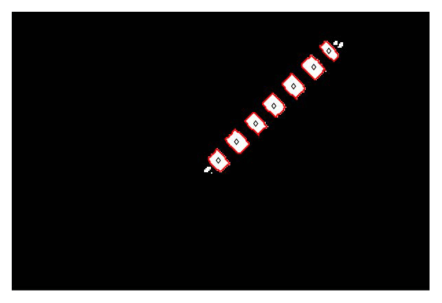
Figure 8Motion analysis of the composite bar analyzed with digital image processing method. Note that red boundaries and diamond symbols represent the profile and the central point of each marker, respectively.
Here, the motion data of the composite bar during the contact-impact event has been explained in detail. The position of the closest center point rc(1), the velocity of the closest center point vc(1), and the angular velocity of the composite bar ω are determined and shown in Figs. 9–11 respectively.
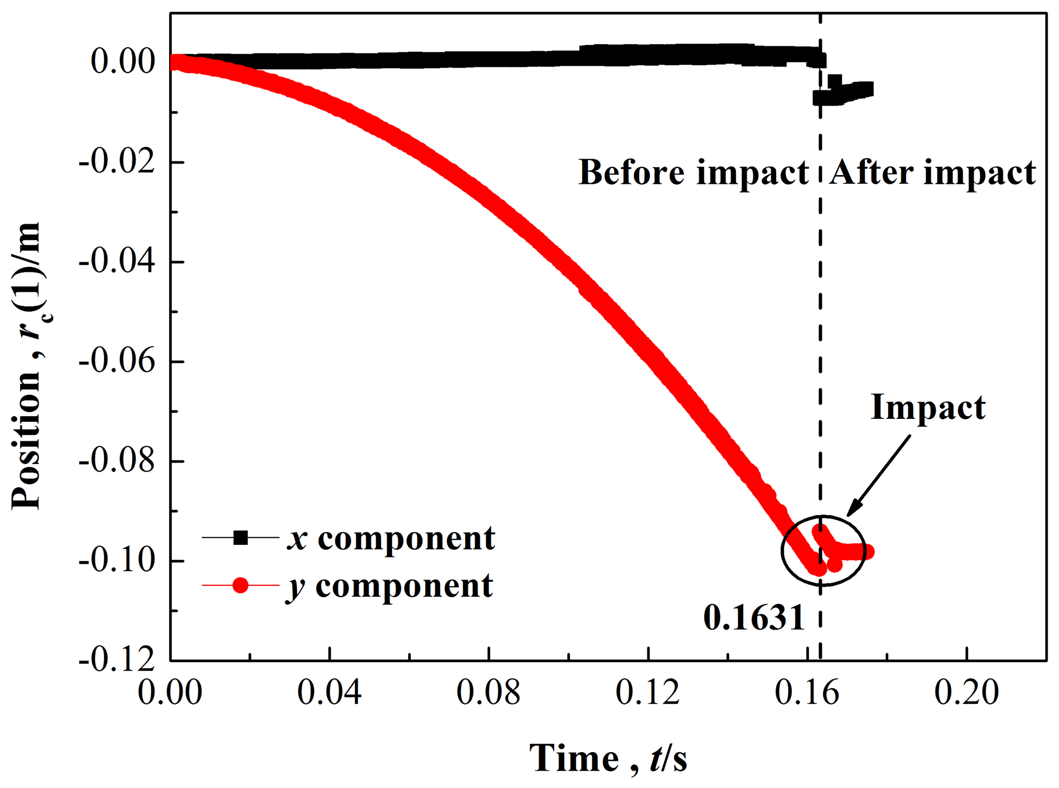
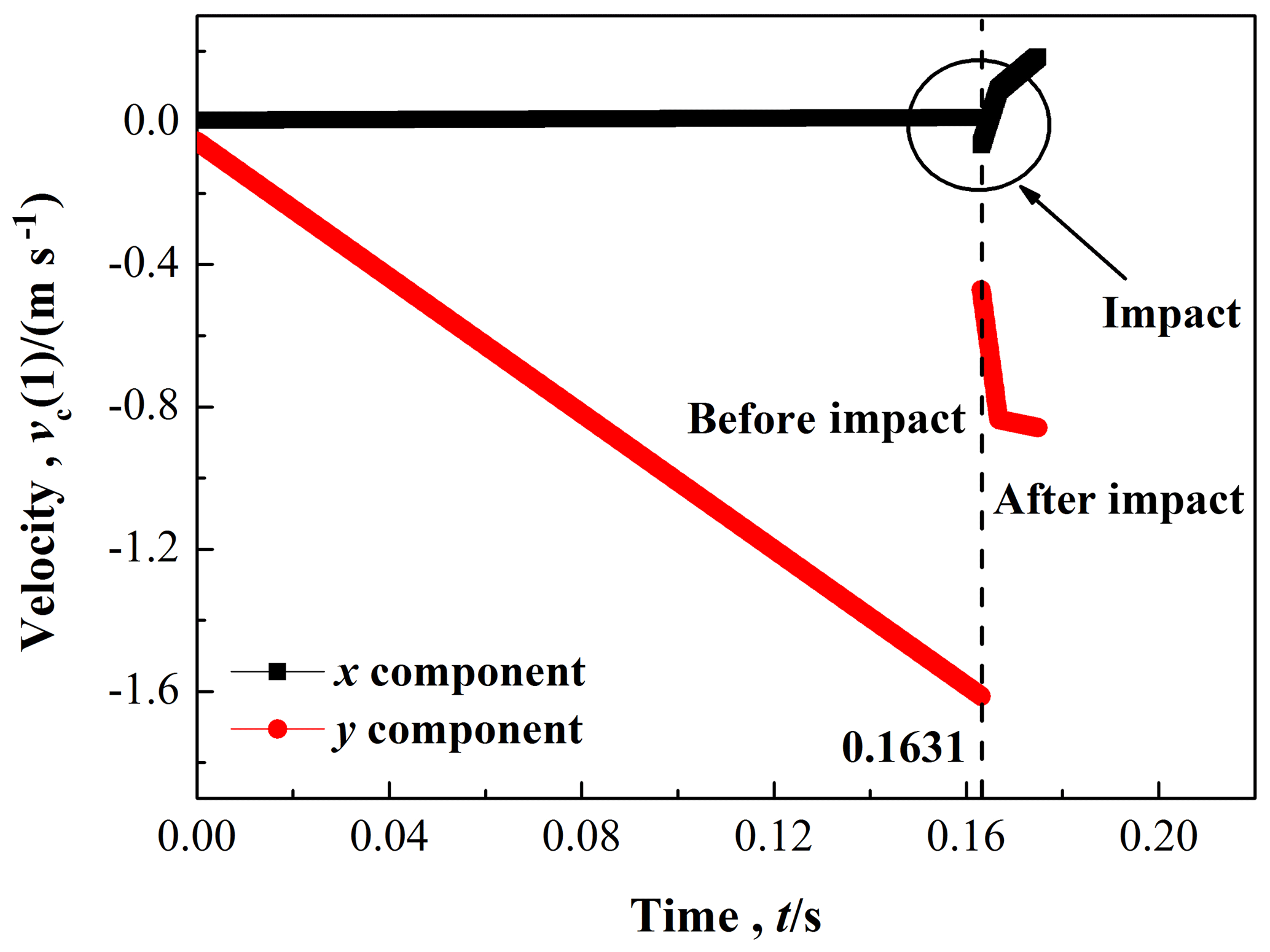
Figure 10 shows the tangential and normal components of the position and velocity of the closest center point. For this case, the impact occurs at t≈0.1631 s. The normal velocities before and after the contact-impact are −1.61353 and −0.472 m s−1 respectively. The tangential velocities before and after the contact-impact are 0.01282 and −0.0639 m s−1 respectively. Moreover, the slope of normal velocities before the contact-impact is 9.853 m s−2, which matches the standard gravitational acceleration g (g=9.80665 m s−2), so it also indirectly reveals that the experimental data are reliable.
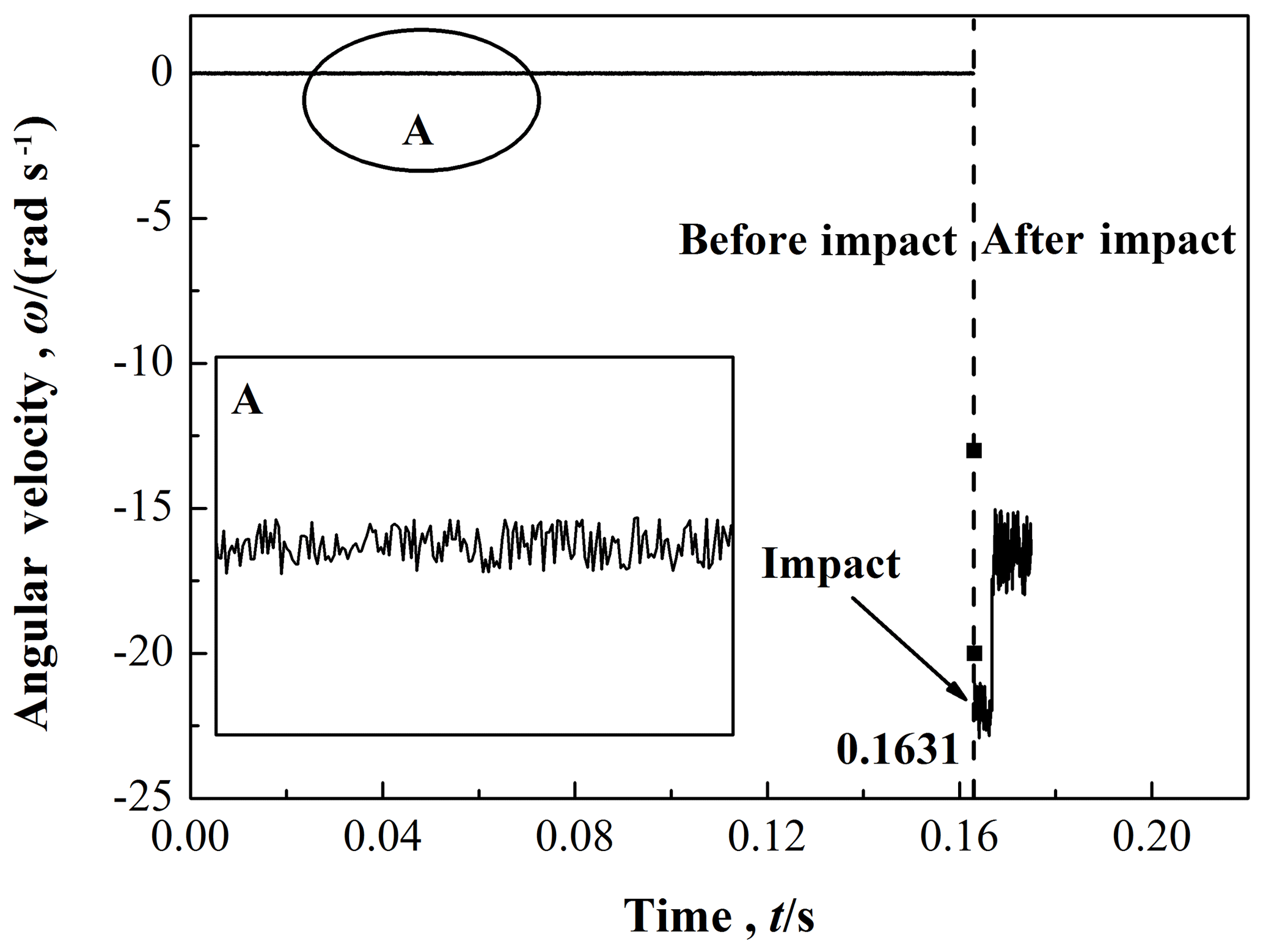
As shown in Fig. 11, the angular velocity before and after the contact-impact are ωb=0.00581 rad s−1 and rad s−1 respectively. The angular velocity presents hardly any differences before the impact occurs, but there are slight fluctuations.
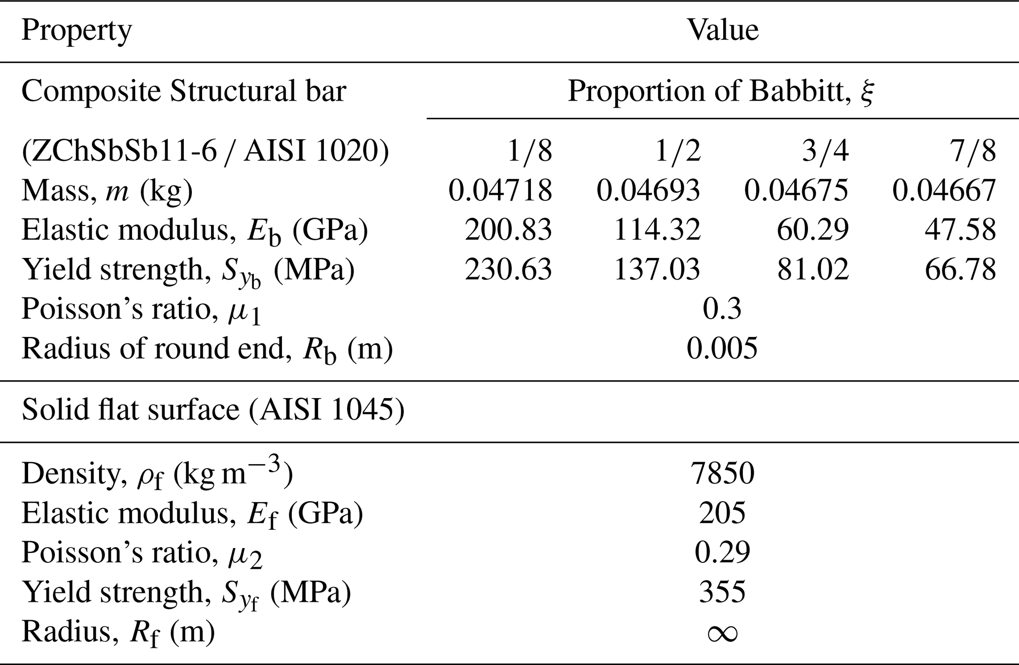
In this work, the numerical simulations of the dynamic model of the composite structural bar with a solid flat surface during the oblique contact-impact events have been compared with the experimental results in terms of the linear and the angular motion, i.e., the normal and tangential velocities of the contact point after the impact, and the rebound angular velocities of the impacting object (i.e. composite structural bar). In addition, the coefficient of restitution, the relation of contact force and contact deflection, and the permanent deformation were also compared for the composite structural bars with different proportions of Babbitt. Table 2 shows the material properties and the geometrical dimensions used for the numerical simulations.
Table 2The material properties of the composite structural bar and the solid flat surface.
5.1 Critical angles
Figure 12 depicts Δ, which shows the condition to determine whether the composite structural bar slides or not on the solid flat surface, as a function of initial impact angle. All curves with different proportion of Babbitt present the approximate W distribution in the interval (0, 90∘), and three critical initial impact angles (at Δ=0) are found. For the composite structural bar with (i.e. the legend of black square), three critical initial impact angles are 27.3, 37.4, and 66.3∘ respectively. From the variation curves shown in Fig. 12, we can also know that near the first lowest point, as the proportion of Babbitt, ξ, increases the first and second critical initial impact angle, θ, decreases. On the contrary, as the proportion of Babbitt, ξ, increases the third critical initial impact angle, θ, increases. That is to say, the critical angles are prominently different for the composite structural bar with different ξ during contact-impact events.
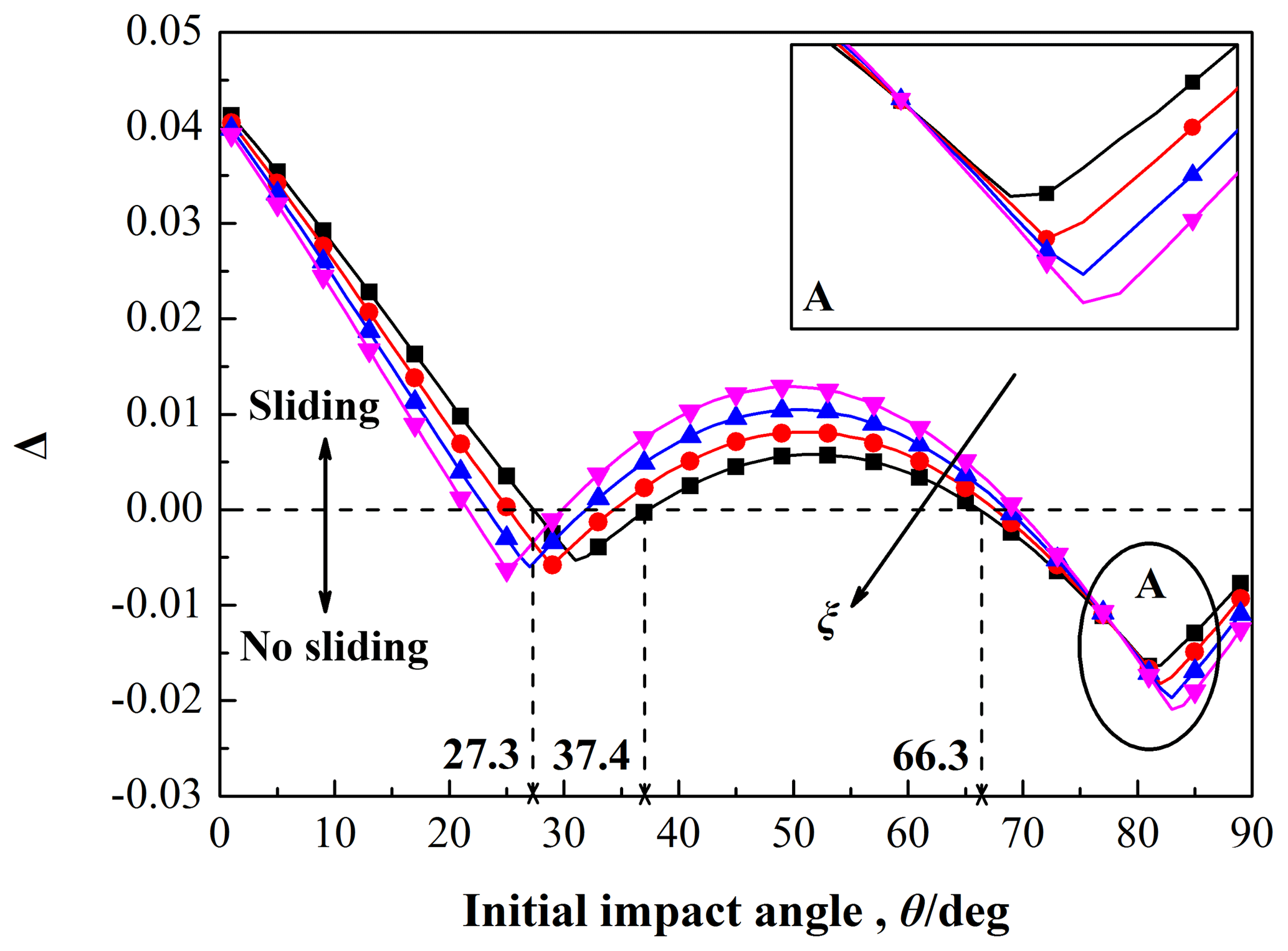
Figure 12The condition for sliding or no sliding as a function of initial impact angle, with the properties described in Table 2, and with ξ varied from 1∕8 to 7∕8.
5.2 Rebound velocity
The tangential and normal velocities of the contact point after the impact with for different proportions of Babbitt are compared with the experimental results, and the results are shown in Figs. 13–14. For each specimen with different proportion of Babbitt, the maximum and average relative errors of the rebound normal and tangential velocity are also calculated by comparing the numerical value with the experimental results. All simulation results almost depict the same trend with the experimental data.
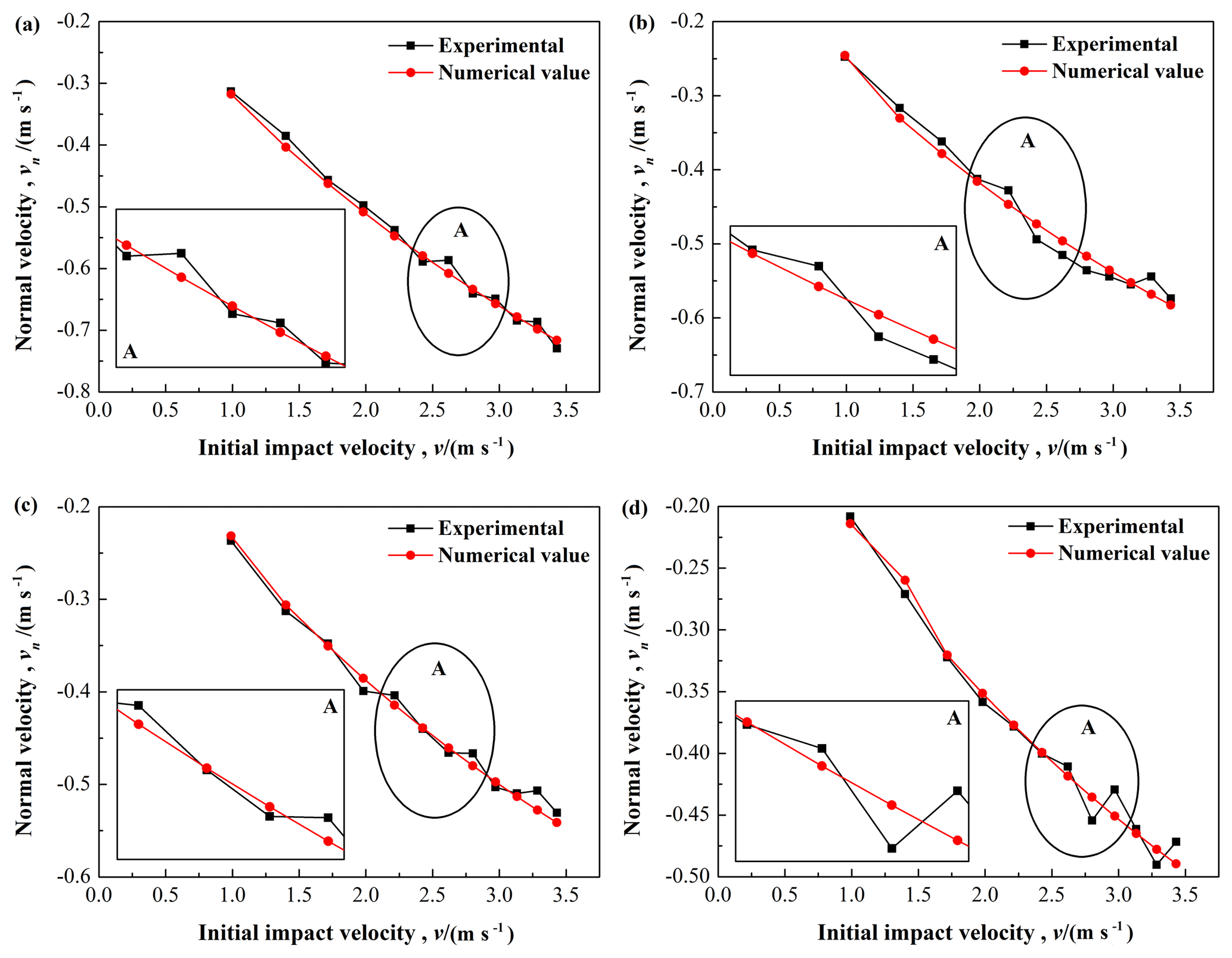
Figure 13Comparison between the simulations and the experimental results for the rebound normal velocity: (a) , (b) , (c) , and (d) .
Figure 13 presents the rebound normal velocity increases as the initial impact velocity increases. All of the specimens show same trend, while numerical values are slightly different from the experimental results. For shown in Fig. 13a, the maximum and average relative errors of the rebound normal velocity are 4.69 % and 2.14 % respectively. For , 3∕4, and 7∕8 shown in Fig. 13b–d, the maximum and average relative errors of the rebound normal velocity in turn are 4.49 % and 2.98 %, 4.16 % and 2.12 %, 5.05 % and 2.56 %, respectively.
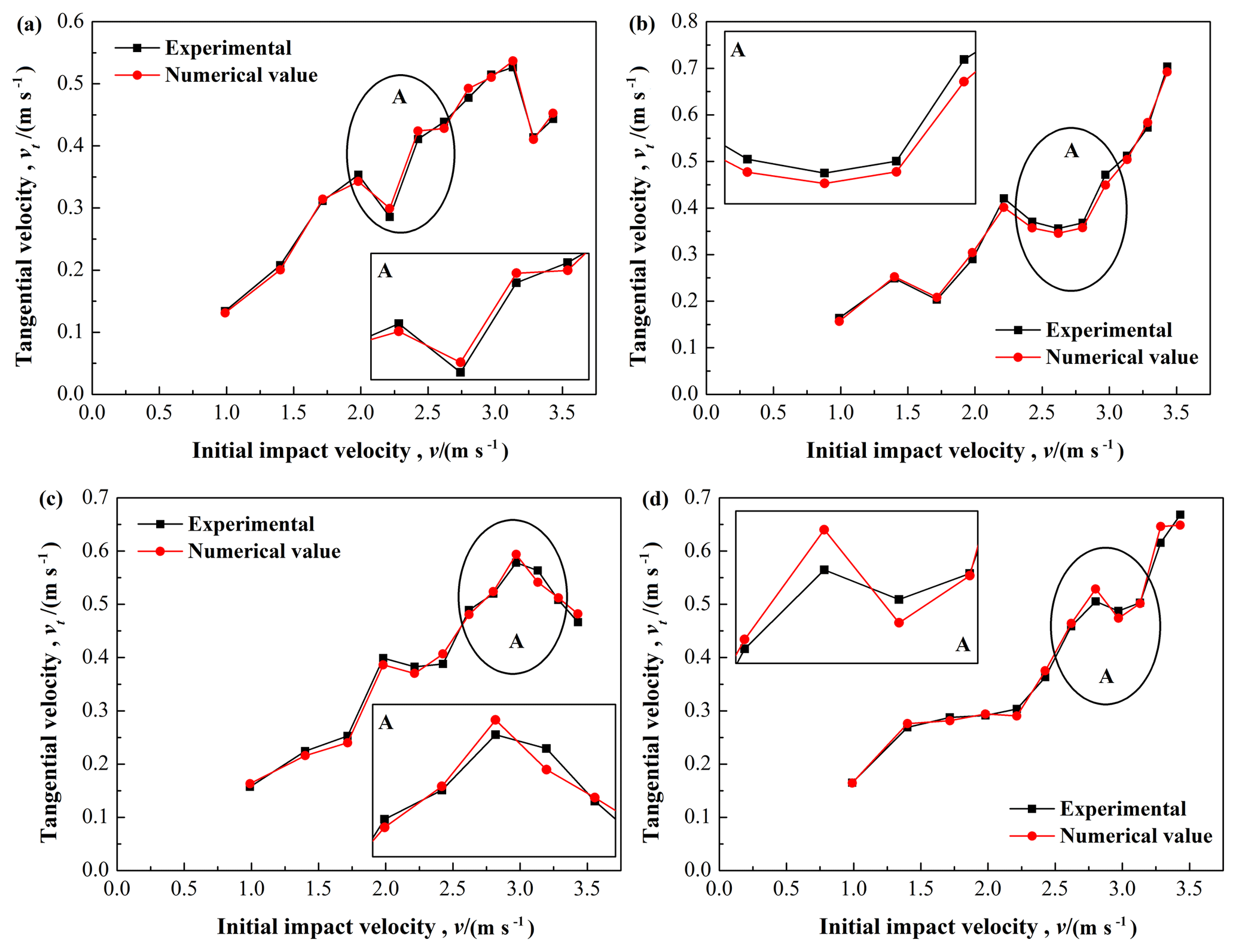
Figure 14Comparison between the simulations and the experimental results for the rebound tangential velocity: (a) , (b) , (c) , and (d) .
Figure 14 shows the rebound tangential velocity of the composite bar for different initial impact velocities and with the different proportion of Babbitt. Similar to the rebound normal velocity results, the rebound tangential velocity increases as the initial impact velocity increases with the same trend for each specimen. However, all curves exist obvious fluctuations, which indirectly indicates that the effect of friction and what role of it in contact-impact events are needed to be further explored. For , 1∕2, 3∕4, and 7∕8 shown in Fig. 14a–d, the maximum and average relative errors of the rebound tangential velocity in turn are 4.84 % and 2.58 %, 4.92 % and 3.21 %, 4.97 % and 3.22 %, 4.96 % and 2.72 %, respectively.
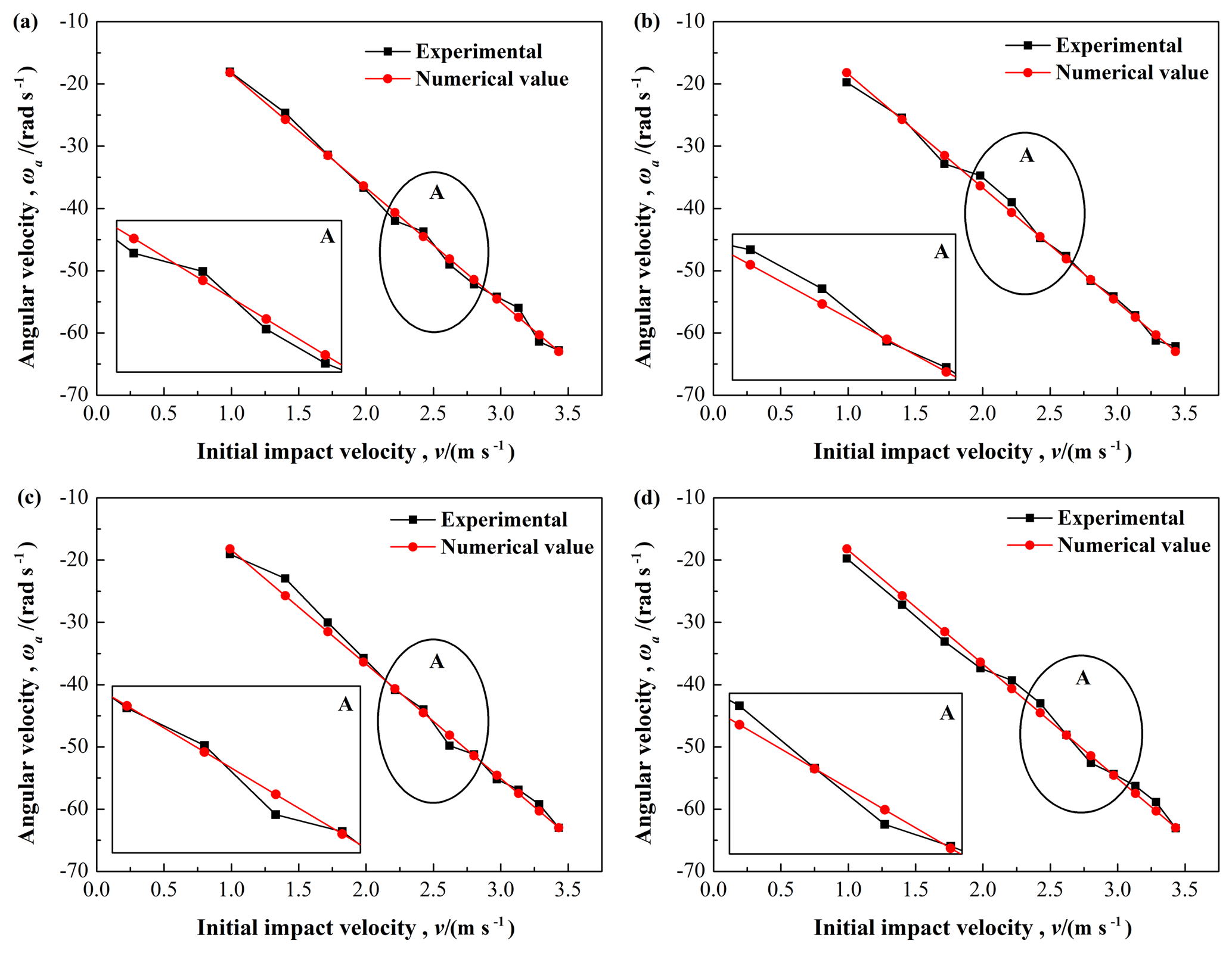
Figure 15Comparison between the simulations and the experimental results for the rebound angular velocity: (a) , (b) , (c) , and (d) .
Furthermore, the angular velocity of the composite structural bar after impact has been analyzed and compared with the experiments, as shown in Fig. 15. The rebound angular velocity also increases with the increase of initial impact velocity for each specimen. No significant difference is seen between the simulations and the experiments. All the average relative errors are less than 5 %, and the maximum error for different proportion of Babbitt does not exceed 15 %, indicating that the established model is effective. From the above analysis, it can be seen that all relative errors of the established dynamic model are small, which reveals that the simulations are in good agreement with the experimental results.
5.3 Coefficient of restitution
As is well known, the coefficient of restitution is a key parameter, which reflects the displacement restoring capacity of colliding bodies during the contact-impact. Based on its definition, the coefficient of restitution, e, can be calculated and averaged for all of the experiments using the following equation:
where and are the normal velocity of the contact point E of the composite bar before and after the contact-impact, respectively. The velocity of the solid flat surface before and after the contact-impact is considered equal to zero.
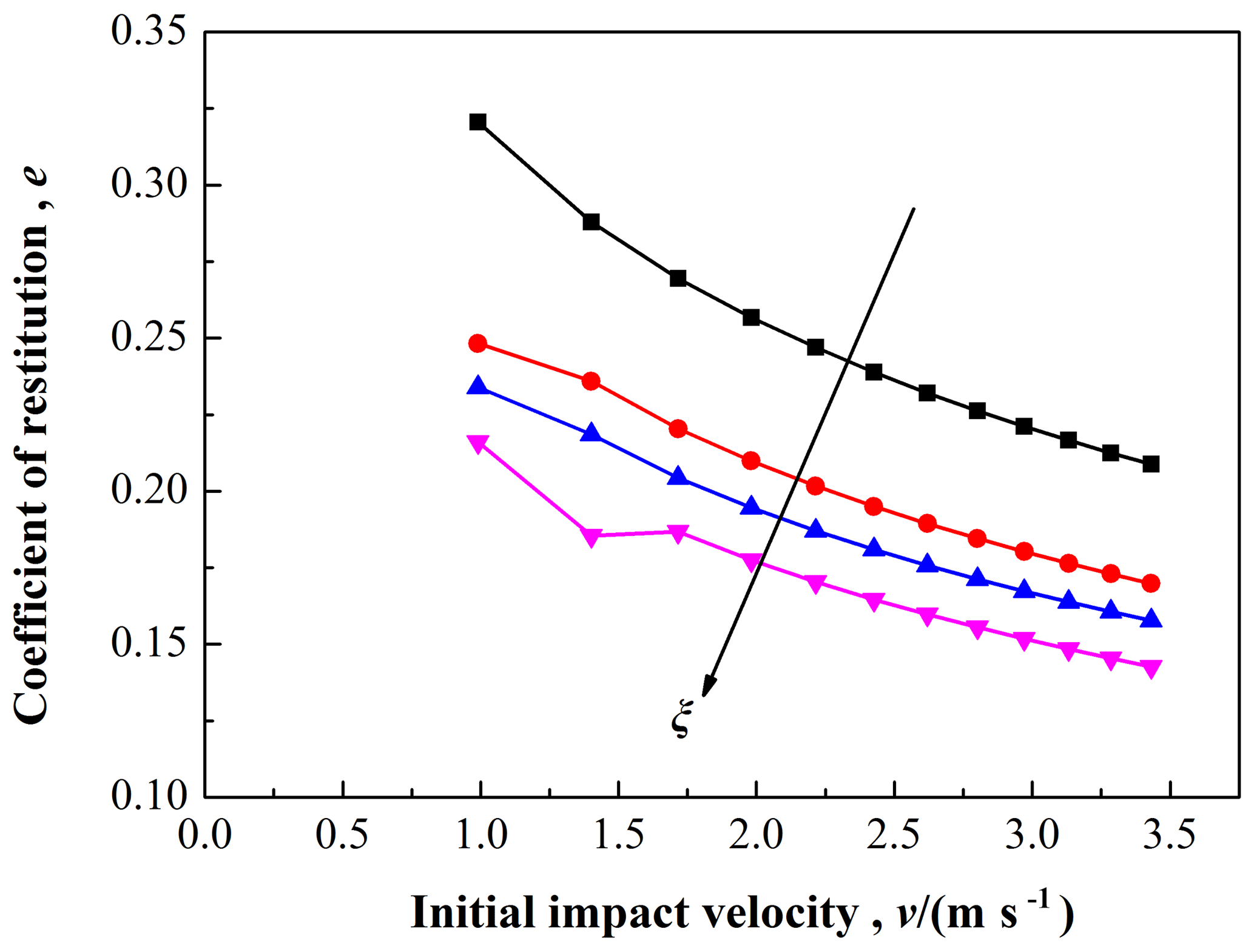
Figure 16The coefficient of restitution as a function of initial impact velocity, and with ξ varied from 1∕8 to 7∕8.
Figure 16 shows the coefficient of restitution, e, for different initial impact velocities, v, from experiments with different proportion of Babbitt, ξ. Experimental results indicate that all curves with ξ varied from 1∕8 to 7∕8 show the same trend, and the coefficient of restitution decreases as the initial velocities increases. In addition, the coefficient of restitution e, decreases with the increase of the proportion of Babbitt, ξ. This also reveals that as the proportion of Babbitt, ξ, increases the composite structural bar presents a characteristic of ease of deflection. Obviously, the behavior of structural entity is mostly governed by the weak or soft material of composite structures.
5.4 Contact force
Figure 17 shows the relationship of contact force and contact deflection for each specimen with different proportion of Babbitt in the case of maximum drop height H=0.60 m. In comparing with each specimen, the variation curves show similar trends in the whole contact-impact. For all of the curves the contact force starts at zero and increases with an increasing rate until the maximum deformation (δm) happens; and then decreases with a decreasing rate until the end of the contact-impact, i.e., at this instance the contact deflection (δ) of the contact point E reaches the permanent deformation (δr). Take the curve of as an example, the relative error for the maximum deformation (δm=66.05 µm) and the permanent deformation (δr=61.12 µm) is 7.46 %; and, it is also the maximum relative error within 10 % for all curves shown in Fig. 17. In addition, as the proportion of Babbitt (ξ) increases the maximum contact force (Fm) decreases, but the permanent deformation (δr) increases. This indicates that the contact-impact behavior of structural entity is closely related to the inherent properties of the elasto-plastic material, especially for the weak material of composite structures.
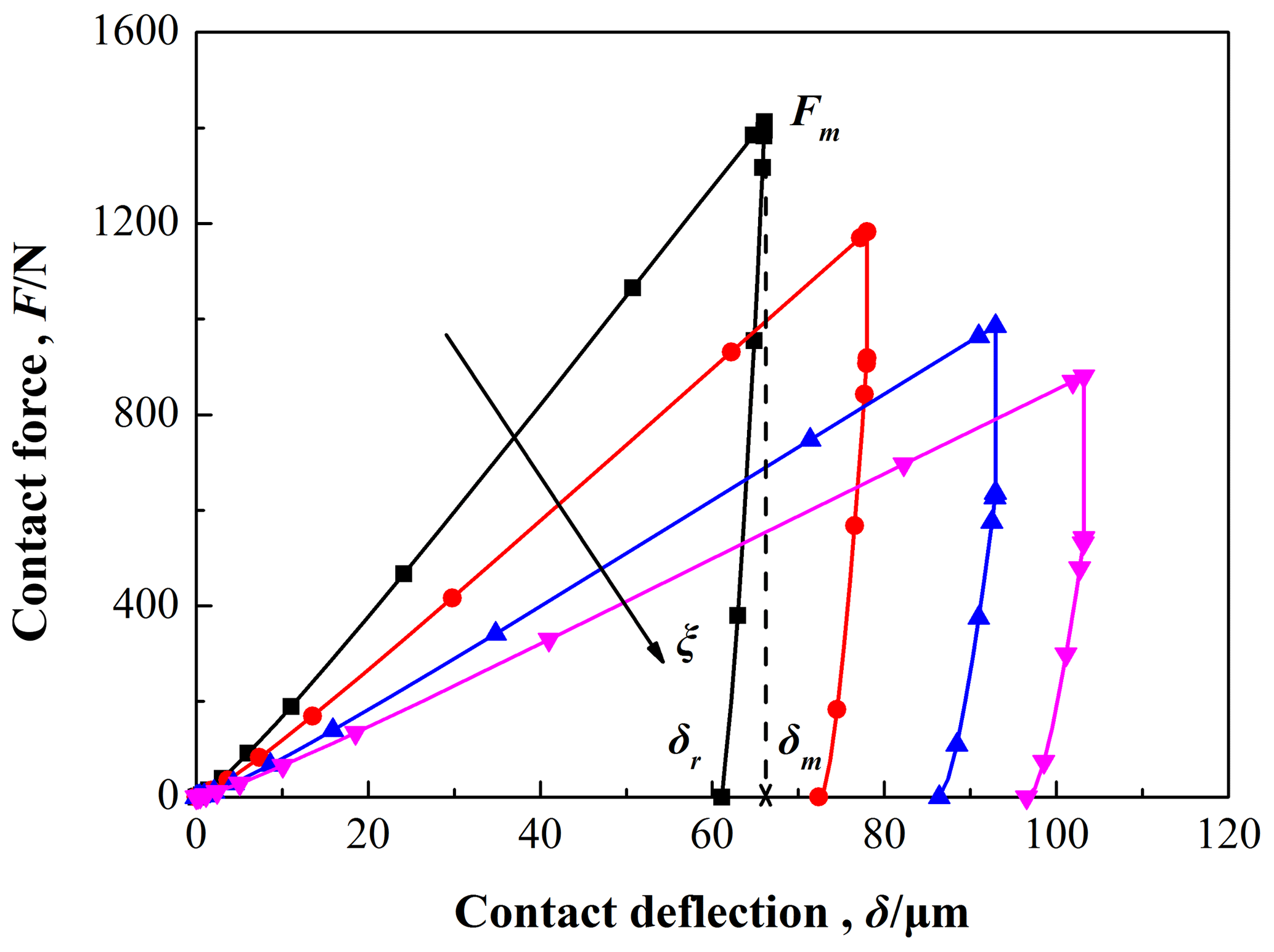
Figure 17The contact force as a function of contact deflection for H=20 cm, and with ξ varied from 1∕8 to 7∕8.
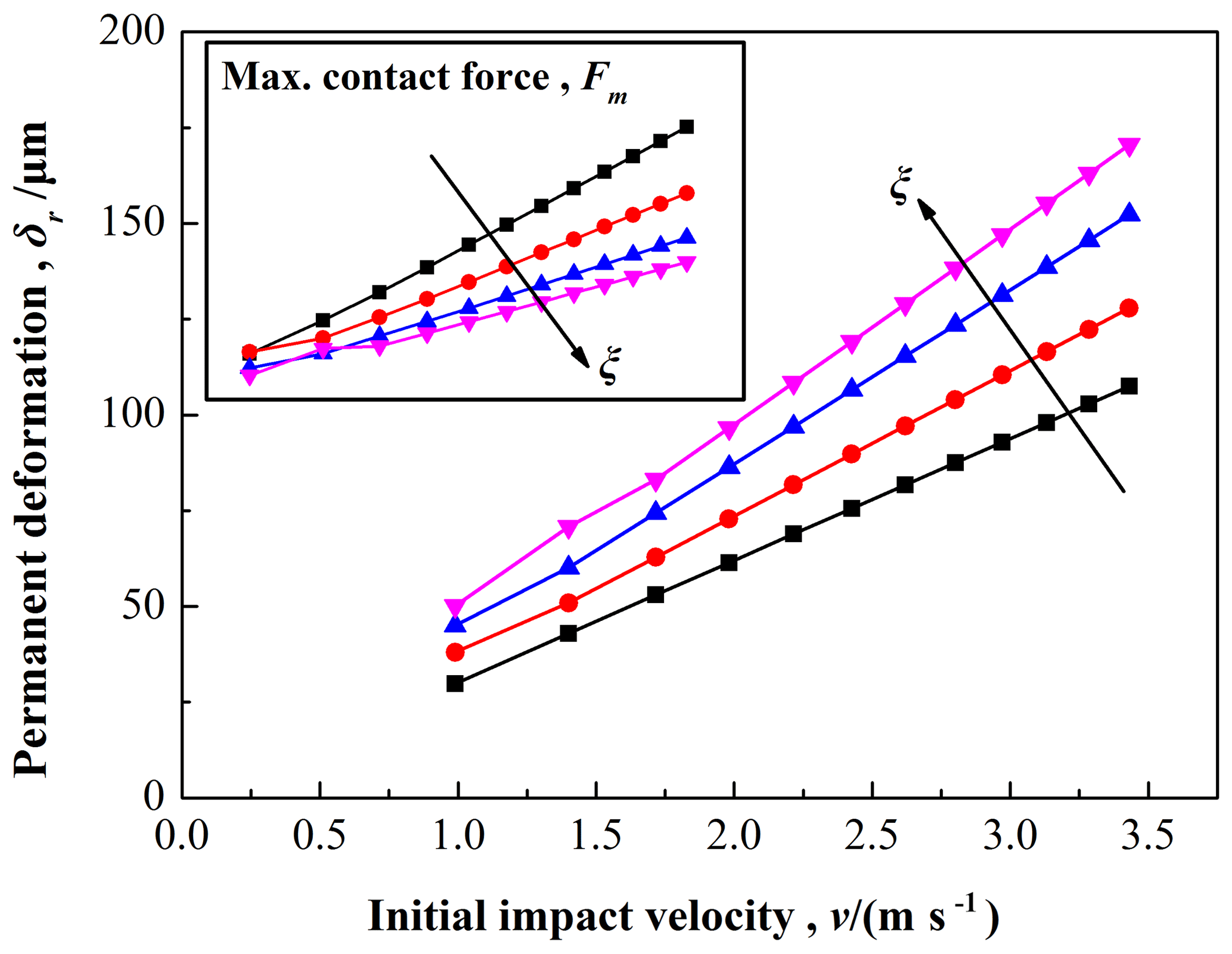
Figure 18The permanent deformation as a function of initial impact velocity, and with ξ varied from 1∕8 to 7∕8.
Figure 18 shows the permanent deformation, δr, for different initial impact velocities, v, from experiments with different proportion of Babbitt, ξ. As the initial impact velocity (v) increases, the permanent deformation (δr) increases; and while with the increase of proportion of Babbitt (ξ), the permanent deformation (δr) also increases. For the maximum contact force during contact-impact events, as the initial impact velocity (v) increases, Fm increases; however, as proportion of Babbitt (ξ) increases, Fm decreases. Thus it can be seen that the more easily the impacting object is deformed, the small the contact force during the contact-impact, which also indicates the yield strength of weak material is a very significant parameter in the event of collision.
Experimental studies have shown that the solid flat surface has no deformed region and only the contact deflection happens on the composite bar, which is well matching the flattening models. These phenomena can indirectly illustrate the accuracy of established model based on the flattening model. For the indentation models, we can use a profilometer or a CLSM (confocal laser scanning microscope) to measure the profile of the deformed region (i.e. permanent deformation) on the solid flat surface after each impact. But so far, there is still no effective way to measure the contact deflection on the composite structural bar. So, additional experimental studies of permanent deformation during contact-impact are needed to perform in order to get a wider range of established model such as to predict the contact force and contact deflection.
In this study, the oblique contact-impact of the composite structural bar composed of Babbitt layer and steel substrate with a solid flat surface has been analyzed theoretically and numerically. The dynamic motion of the composite structural bar with vibration response during the contact-impact has been established using the momentum theorem and assumed mode method. The instantaneous contact forces during different impact phases were also analyzed based on modified Jackson–Green model. Four sets of experiments (i.e. different proportion of Babbitt, ) for the initial angle, , and different initial velocities have been completed. Then, the rebound linear and angular velocity of the contact point of composite bar after contact-impact has been calculated and compared with experimental results. In addition, the coefficient of restitution, the relation of contact force and contact deflection, and the permanent deformation were also compared for the composite structural bars with different ξ.
It has been shown that three critical angles are found to determine whether the composite bar slides or not, but are prominently different for the composite structural bar with different ξ. The comparison for rebound linear and angular velocity between the simulations and the experimental results had yield encourage results, which revealed that the simulations are in good agreement with the experimental results. Moreover, the oblique contact-impact behavior involving the coefficient of restitution, the relation of contact force and contact deflection, and the permanent deformation was explained in detail. First, for the coefficient of restitution, as the proportion of Babbitt, ξ, increases the composite structural bar presents a characteristic of ease of deflection. Obviously, the behavior of structural entity is mostly governed by the weak or soft material of composite structures. Then, for the relation of contact force and contact deflection, the contact-impact behavior of structural entity is closely related to the inherent properties of the elasto-plastic material, especially for the weak material of composite structures. Lastly, for the permanent deformation, the more easily the impacting object is deformed, the small the contact force during the impact, which also indicates the yield strength of weak material is a very significant parameter in the event of collision. Further, due to the limit of measuring the contact deflection on the composite bar, more studies are needed to perform in order to get a wider range of established model.
The data can be made available upon request. Please contact Yao Wang (sjtuyao@sjtu.edu.cn) or Zhuang Fu (zhfu@sjtu.edu.cn).
| [i0, j0, k0] | Cartesian unit vectors in RF(0) |
| [i1, j1, k1] | Cartesian unit vectors in RF(1) |
| B | composite structural bar |
| L | length of composite bar |
| d | diameter of composite bar |
| S | solid flat surface |
| C | center of mass of B |
| A | top point |
| E | contact point |
| P | arbitrary or any point of B |
| G | gravitational force (N) |
| F | contact force during contact-impact (N) |
| θ | initial impact angle (rad or deg) |
| q, q(t) | generalized coordinates |
| generalized speeds | |
| t | time (s) |
| Eb | elastic modulus of composite bars (GPa) |
| ξ | proportion of Babbitt |
| ABabbitt | area of Babbitt (m2) |
| Ab | cross-section area of composite bar (m2) |
| R10 | transformation matrix |
| ω | angular velocity of B (rad s−1) |
| α | angular acceleration of B (rad s−2) |
| rA | position vector of the point A (m) |
| vA | velocity vector of the point A (m s−1) |
| ν, ν(x,t) | longitudinal elastic displacement (m) |
| y, y(x,t) | transverse elastic displacement (m) |
| Φi(x), | mode shape |
| n | number of vibrational modes selected |
| λi | consecutive root of the |
| characteristic equation | |
| rAP | position vector from point A to point P (m) |
| vP | velocity of any point P (m s−1) |
| va | velocity of approach (m s−1) |
| vs | velocity of separation (m s−1) |
| T | kinetic energy of impacting object (J) |
| ρ | mass per unit length (kg m−1) |
| Pj | generalized impulse (N s) |
| Mj | generalized moment (kg m s−1) |
| vE | velocity of contact point E (m s−1) |
| [t1, t2] | impact duration (s) |
| D1, D2 | two bodies during the contact-impact |
| E1, E2 | contact points on the surface of each body |
| e | coefficient of restitution |
| Fn, Ft | impulse components (N s) |
| Δ | a condition used to find |
| the type of the friction | |
| μs | coefficient of static friction |
| μk | coefficient of kinetic friction |
| Fe | contact force for the elastic phase (N) |
| Ef | elastic modulus of the solid flat surface (GPa) |
| μ1, μ2 | Poisson's ratios of two objects in contact-impact |
| Rb, Rf | radii of the bar and the solid flat (m) |
| R | reduced radius (m) |
| E′ | reduced modulus of elasticity (GPa) |
| δ | contact deflection (m) |
| yE | y coordinate of the contact point E in (0) (m) |
| Sy | yield strength (MPa) |
| Fc | critical force at the instant the yield occurs (N) |
| Fp | contact force for the elasto-plastic phase (N) |
| HG | average normal pressure (kgf m−2) |
| δc | critical deformation (m) |
| Fr | contact force for the restitution phase (N) |
| δr | permanent deformation (m) |
| Fm | maximum contact force (N) |
| δm | maximum deformation (m) |
| Rr | radius of the curvature in restitution phase (m) |
| H, v | drop height (m) or initial impact velocity (m s−1) |
| h | arch height of cross-section of B (mm) |
| normal approach velocity of B (m s−1) | |
| normal separation velocity of B (m s−1) | |
| Superscripts/Subscripts | |
| (0) | global reference frame, RF(0) |
| (1) | mobile reference frame, RF(1) |
| i,j, k, r | number |
YW conceived the overall idea of this paper, and performed the specimen fabrication and experiments, and analyzed the data. ZF verified the established model and supervised the whole work. YW and ZF wrote the paper and agreed on the final form of the manuscript.
The authors declare that they have no conflict of interest.
I would like to thank my PhD supervisor Wenjun Meng for his support and feedback provided on this work and gratefully acknowledge to the Oil-film Bearing Branch of Taiyuan Heavy Machinery Group Co., Ltd,. In particular, I also want to gratefully acknowledge Dan B. Marghitu and his research team at Auburn University for the helpful guide on the field of contact mechanics.
This research has been supported by the National Natural Science Foundation of China (grant no. 51875333) and the Project of STCSM (grant no. 17441901000).
This paper was edited by Guimin Chen and reviewed by two anonymous referees.
Appleby-Thomas, G. J., Wood, D. C., Hameed, A., and Leighs, J. A.: On the ballistic response of an aerospace-grade composite panel to non- spheroidised fragment simulants, Compos. Struc., 119, 90–98, https://doi.org/10.1016/j.compstruct.2014.08.016, 2015.
Babu, M. V. S., Krishna, A. R., and Suman, K. N. S.: Review of journal bearing materials and current trends, Am. J. Mater. Sci. Technol., 4, 72–83, https://doi.org/10.7726/ajmst. 2015.1006, 2015.
Banerjee, A., Chanda, A., and Das, R.: Historical origin and recent development on normal directional impact models for rigid body contact simulation: a critical review, Arch. Comput. Methods Eng., 24, 397–422, https://doi.org/10.1007/s11831-016-9164-5, 2017.
Bartier, O., Hernot, X., and Mauvoisin, G.: Theoretical and experimental analysis of contact radius for spherical indentation, Mech. Mater., 42, 640–656, https://doi.org/10.1016/j.mechmat.2010.03.003, 2010.
Bazrafshan, M., Ahmadian, H., and Jalali, H.: Modeling the interaction between contact mechanisms in normal and tangential directions, Int. J. Non. Linear Mech., 58, 111–119, https://doi.org/10.1016/j.ijnonlinmec.2013.09.002, 2014.
Boroujerdy, M. S. and Kiani, Y.: Low velocity impact analysis of composite laminated beams subjected to multiple impacts in thermal field, ZAMM J. Appl. Math. Mech., 96, 843–856, https://doi.org/10.1002/zamm.201500132, 2016.
Brake, M. R.: An analytical elastic-perfectly plastic contact model, Int. J. Solids Struct., 49, 3129–3141, https://doi.org/10.1016/j.ijsolstr.2012.06.013, 2012.
Brake, M. R. W.: An analytical elastic plastic contact model with strain hardening and frictional effects for normal and oblique impacts, Int. J. Solids Struct., 62, 104–123, https://doi.org/10.1016/j.ijsolstr.2015.02.018, 2015.
Christoforou, A. P. and Yigit, A. S.: Inelastic impact and the coefficient of restitution, J. Eng. Res., 4, 194–213, 2017.
Dong, X. Y., Yin, X. C., Deng, Q. M., Yu, B., Wang, H., Weng, P. P., Chen, C. Q., and Yuan, H.: Local contact behavior between elastic and elastic-plastic bodies, Int. J. Solids Struct., 150, 22–39, https://doi.org/10.1016/j.ijsolstr.2018.05.020, 2018.
Flores-Abad, A., Ma, O., Pham, K., and Ulrich, S.: A review of space robotics technologies for on-orbit servicing, Prog. Aerosp. Sci., 68, 1–26, https://doi.org/10.1016/j.paerosci.2014.03.002, 2014.
Jackson, R. L. and Green, I.: A statistical model of elasto-plastic asperity contact between rough surfaces, Tribol. Int., 39, 906–914, https://doi.org/10.1016/j.triboint.2005.09.001, 2006.
Gheadnia, H., Cermik, O., and Marghitu, D. B.: Experimental and theoretical analysis of the elasto-plastic oblique impact of a rod with a flat, Int. J. Impact Eng., 86, 307–317, https://doi.org/10.1016/j.ijimpeng.2015.08.007, 2015a.
Ghaednia, H., Marghitu, D. B., and Jackson, R. L.: Predicting the permanent deformation after the impact of a rod with a flat surface, J. Tribol., 137, 011403, https://doi.org/10.1115/1.4028709, 2015b.
Ghaednia, H., Pope, S. A., Jackson, R. L., and Marghitu, D. B.: A comprehensive study of the elasto-plastic contact of a sphere and a flat, Tribol. Int., 93, 78–90, https://doi.org/10.1016/j.triboint.2015.09.005, 2016.
Ghaednia, H., Cermik, O., Marghitu, D. B., and Kardel, K.: Collision measurements using digital image correlation techniques, Int. J. Mech. Sci., 131, 836–846, https://doi.org/10.1016/ j.ijmecsci.2017.07.025, 2017a.
Ghaednia, H., Wang, X. Z., Saha, S., Xu, Y., Sharma, A., and Jackson, R. L.: A review of elastic-plastic contact mechanics, Appl. Mech. Rev., 69, 060804, https://doi.org/10.1115/1.4038187, 2017b.
Hunt, K. H. and Crossley, F. R. E.: Coefficient of restitution interpreted as damping in vibroimpact, J. Appl. Mech., 42, 440–445, https://doi.org/10.1115/1.3423596, 1975.
Kane, T. R. and Levinson, D. A.: Dynamics, theory and applications, McGraw Hill, Ithaca, NY, USA, 1985.
Khulief, Y. A.: Modeling of impact in multibody systems: an overview, J. Comput. Nonlinear Dyn., 8, 021012, https://doi.org/10.1115/1.4006202, 2013.
Kogut, L. and Etsion, I.: Elastic-plastic contact analysis of a sphere and a rigid flat, J. Appl. Mech., 69, 657–662, https://doi.org/10.1115/1.1490373, 2002.
Kogut, L. and Komvopoulos, K.: Analysis of the spherical indentation cycle for elastic-perfectly plastic solids, J. Mater. Res., 19, 3641–3653, https://doi.org/10.1557/ JMR.2004.0468, 2004.
Li, S. J., Wang, Y., Xiang, D., and Meng, W. J.: Impact factor of binding interface on ZChSbSb11-6/20 steel composites, Rare Met. Mater. Eng., 45, 2555–2560, 2016.
Ma, D. L. and Liu, C. S.: Contact law and coefficient of restitution in elasto-plastic spheres, J. Appl. Mech., 82, 121006, https://doi.org/10.1115/1.4031483, 2015.
Mao, Y. Q., Hong, L., Ai, S. G., Fu, H. L., and Chen, C. P.: Dynamic response and damage analysis of fiber-reinforced composite laminated plates under low-velocity oblique impact, Nonlinear Dyn., 87, 1511–1530, https://doi.org/10.1007/s11071-016-3130-5, 2017.
Meng, W. J. and Wang, Y.: Comprehensive analyses of the elasto-plastic oblique contact-impact with vibration response, Proceedings of the Institution of Mechanical Engineers, Part K: Journal of Multi-Body Dynamics, 233, 441–454, https://doi.org/10.1177/1464419318801732, 2019.
Park, H.: Investigation on low velocity impact behavior between graphite/epoxy composite and steel plate, Compos. Struct., 171, 126–130, https://doi.org/10.1016/j.compstruct.2017.03.032, 2017.
Shafei, A. M. and Shafei, H. R.: Oblique impact of multi-flexible-link systems, J. Vib. Control, 24, 904–923, https://doi.org/10.1177/1077546316654854, 2018.
Vu-Quoc, L., Zhang, X., and Lesburg, L.: A normal force-displacement model for contacting spheres accounting for plastic deformation: force-driven formulation, J. Appl. Mech., 67, 363–371, https://doi.org/10.1115/1.1305334, 2000.
Wang, H., Yin, X. C., Qi, X. L., and Deng, Q. M., Yu, B., and Hao, Q. M.: Experimental and theoretical analysis of the elastic-plastic normal repeated impacts of a sphere on a beam, Int. J Solids Struct., 109, 131–142, https://doi.org/10.1016/j.ijsolstr.2017.01.014, 2017a.
Wang, H., Yin, X. C., Deng, Q. M., Yu, B., Hao, Q. M., and Dong, X. Y.: Experimental and theoretical analyses of elastic-plastic repeated impacts by considering wave effects, Eur. J. Mech. A-Solid., 65, 212–222, https://doi.org/10.1016/j.euromechsol.2017.04.006, 2017b.
Wang, J. M., Meng, F. N., Zhang, X. T., Liang, Y. N., and Li, Z. X.: Mathematical model and algorithm of interface singular stress field of oil-film bearing, Tribol. Int., 116, 351–361, https://doi.org/10.1016/j.triboint.2017.07.026, 2017.
Wang, Y., Wang, J. M., Huang, Y. Q., and Xiang, D.: Experiment and simulation research on optimum thickness of Tin interfacial layer, J. Mech. Eng., 51, 106–113, https://doi.org/10.3901/JME.2015.20.106, 2015.
Wang, Y., Li, S. J., Xiang, D., and Meng, W. J.: Experimental and theoretical analyses of the contact-impact behavior of Babbitt ZChSnSb11-6, Proceedings of the Institution of Mechanical Engineers, Part L: Journal of Materials: Design and Applications, https://doi.org/10.1177/1464420717739334, 2017a.
Wang, Y., Xiang, D., and Meng, W. J.: Simulation and experiments of binding strength of different binding interfaces on ZChSbSb11-6/20 steel composites, China Mech. Eng., 28, 101–106, 112, https://doi.org/10.3969/j.issn.1004-132X.2017.01.017, 2017b.
Wang, Y., Meng, W. J., Xiang, D., and Li, S. J.: Experimental and numerical analysis of the elasto-plastic oblique contact-impact dynamics using digital image processing method, J. Mech. Eng., 55, 81–90, https://doi.org/10.3901/JME.2019.01.081, 2019.
Xie, W. B., Zhang, W., Kuang, N. H., Li, D. C., Huang, W., Gao, Y. B., Ye, N., Guo, L. C., and Ren, P.: Experimental investigation of normal and oblique impacts on CFRPs by high velocity steel sphere, Compos. Part B-Eng., 99, 483–493, https://doi.org/10.1016/j.compositesb.2016.06.020, 2016.
Ye, N. and Komvopoulos, K.: Indentation analysis of elastic-plastic homogeneous and layered media: Criteria for determining the real material hardness, J. Tribol., 125, 685–691, https://doi.org/10.1115/1.1572515, 2003.
Yuan, W., Li, L., Zhang, D. G., and Hong, J. Z.: New method for oblique impact dynamics research of a flexible beam with large overall motion considering impact friction force, Acta Mech. Sin., 32, 720–730, https://doi.org/10.1007/s10409-016-0576-0, 2016.
Zhang, D. Y., Ho, J. K. L., Dong, G. N., Zhang, H., and Hua, M.: Tribological properties of Tin-based Babbitt bearing alloy with poly urethane coating under dry and starved lubrication conditions, Tribol. Int., 90, 22–31, https://doi.org/10.1016/j.triboint.2015.03.032, 2015.
Zhikharev, M. V. and Sapozhnikov, S. B.: Two-scale modeling of high-velocity fragment GFRP penetration for assessment of ballistic limit, Int. J. Impact Eng., 101, 42–48, https://doi.org/10.1016/j.ijimpeng.2016.08.005, 2017.