the Creative Commons Attribution 4.0 License.
the Creative Commons Attribution 4.0 License.
 | 04 Apr 2019
Quasi-static axial crushing of hexagonal origami crash boxes as energy absorption devices
Jiayao Ma
Huaping Dai
Mengyan Shi
Yan Chen
Zhong You
Thin-walled tubes are widely used as energy absorption devices for their low cost and high manufacturability. Introduction of the origami technique enables the tube to follow a pre-determined failure mode and to improve its energy absorption efficiency. This paper examines the energy absorption characteristics of the origami crash box under quasi-static axial crushing. Both experimental and numerical results show that the origami pattern develops a diamond-shaped mode, bringing a reduction in initial peak force and a significant increase in energy absorption compared to the conventional hexagonal tube. The sensitivity of its energy absorption performance to various parameters is studied, and it is shown to achieve 68.29 % increase in the specific energy absorption and 13.91 % reduction in the initial peak force in the optimal case. Furthermore, an analytical solution is presented for the energy absorption, which achieves reasonable agreement with the numerical results.
- Article
(4474 KB) - Full-text XML
- BibTeX
- EndNote


Thin-walled tubes have been widely employed as energy absorption devices because of their excellent mechanical properties, high manufacturability and low cost (Lu and Yu, 2003). The applications range from automobile crash cans (Martinez et al., 2004) and primary energy absorbers on trains (Tyrell et al., 2006) to helicopter landing gears (Airoldi and Janszen, 2005).
Significant efforts have been taken to study the thin-walled tubes under axial crushing. The crushing of circular tubes was found to develop a diamond mode or a concertina mode or a mixture of the two, which depends on its material and geometry (Alexander, 1960; Wierzbicki et al., 1992; Guillow et al., 2001). Similarly, the crushing of square tubes features three types of failure modes, i.e., the symmetric mode, asymmetric mode A and asymmetric mode B (Wierzbicki and Abramowicz, 1983; Abramowicz and Jones, 1984; Abramowicz and Jones, 1986). To estimate the energy absorption of square tubes, Wierzbicki and Abramowicz (1983) proposed a super folding element theory. Later, this theory was further improved by taking the effective crushing distance into account (Abramowicz, 1983). Besides that, the study of polygonal tubes, which are widely used in practical applications, also received much attention. For instance, Mamalis et al. (1991) have observed four failure modes during the axial crushing of octagonal tubes. The effects of cross-sectional shape and geometric parameters were examined through both numerical simulations (Mamalis et al., 2003; Rossi et al., 2005; Fan et al., 2013) and experiments (Zhang and Zhang, 2012). In general, circular tubes can absorb more energy than polygonal and square tubes, but they have a high peak force, which is not suitable for an energy absorption device.
Many efforts have been thus taken to reduce the initial peak force while keeping or increasing the absorbed energy, ranging from introducing dents and grooves (Mamalis et al., 1986; Yang et al., 2017), corrugations (Singace and El-Sobky, 1997; Y. Yang et al., 2016; Wu et al., 2016) into square and circular tubes. Lately, researchers have found that the introduction of origami patterns into thin-wall structures can trigger specific failure modes, which in turn change the structural responses and characteristics. In light of this, Ma and You (2014) designed a type of crash box pattern and had successfully applied it in the square tubes: the origami pattern triggered a complete diamond mode and led to an increase in the absorbed energy and a reduction in the initial peak force. After that, a variety of patterns were designed and applied to tubes of different shapes. For instance, devices constructed by Kite-shape pattern (Ma et al., 2016) and Tachi-Miura polyhedron bellows (Y. Yang et al., 2016) were also developed which achieved an improvement in their energy absorption performance. Besides that, the full-diamond pattern and diamond pattern (K. Yang et al., 2016) were also applied in circular tubes. Additionally, similar efforts were also conducted regarding square, hexagonal, and octagonal tubes. Recently, Song et al. (2012) used an equilateral trapezoid pattern and succeeded in minimizing the initial peak force and the subsequent fluctuations. Collectively these works have contributed to the current understanding of the advantages of employing origami patterns. However, the effectiveness of different origami patterns, as well as various tube shapes varies even though the initial peak force were seen to lower to some extent. Also, less developed are the study of graded origami pattern and the corresponding theoretical effort and analysis.
In this paper, we use a pre-folded crash box pattern to design a hexagonal energy absorption device (Ma and You, 2014, see also recent results in Shi et al., 2018). This device (referred to as the origami crash box hereafter) is studied through a combination of experimental, numerical and theoretical analyses. The present effort starts with the geometry design of origami crash box in Sect. 2 and the fabrication method as well as the experimental setup in Sect. 3. Subsequently, the numerical simulation scheme is briefly covered. After that, in Sect. 5, comparisons between experimental and numerical results are conducted, followed by systematic parametric studies of the layer height and the pre-folding angle. Furthermore, in Sect. 6, an analytical solution is proposed for the energy absorption based on a suitably chosen basic folding element.
The crash box pattern (Ma and You, 2014) is shown in Fig. 1a with solid and dash lines representing mountain and valley creases respectively. In this study, we considered the setup of six diamond lobes per layer, and Fig. 1b shows a typical single-layer hexagonal origami crash box. The geometry of the crash box can be defined by three independent parameters, i.e., side length b, pre-folding angle θ, and layer height h. Corner width c, layer length l, and sector angle φ can be calculated from Eqs. (1), (2) and (3), respectively.
Besides, geometric constraints require that,
Otherwise the adjacent lobes at the corners would interfere with each other. Substituting Eq. (1) into Eq. (4), we obtain
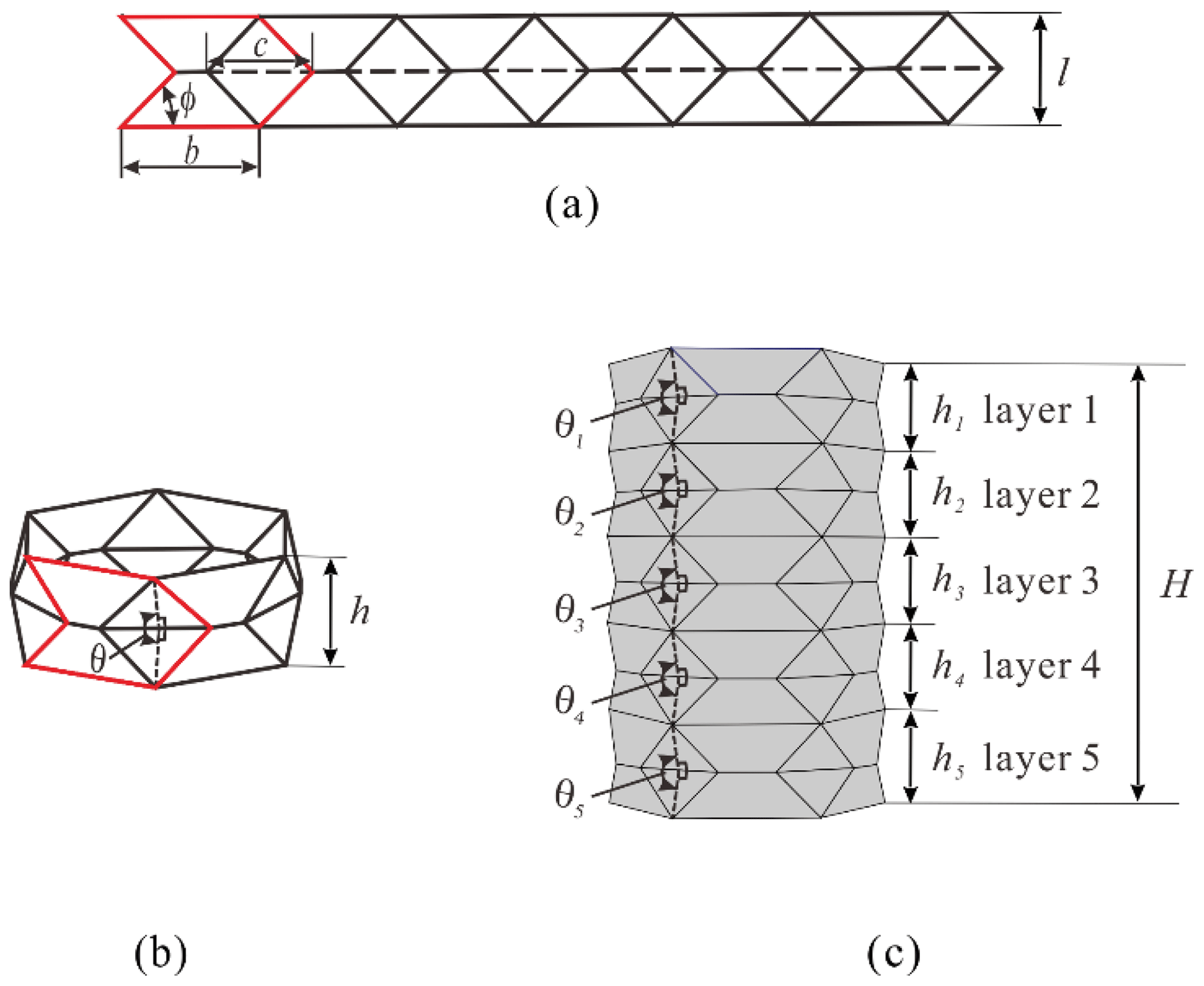
Figure 1Geometry of the origami crash box: (a) the crease pattern; (b) a single-layer crash box; (c) a five-layer crash box.
Table 1Geometrical parameters and numerical results of uniform origami crash boxes.
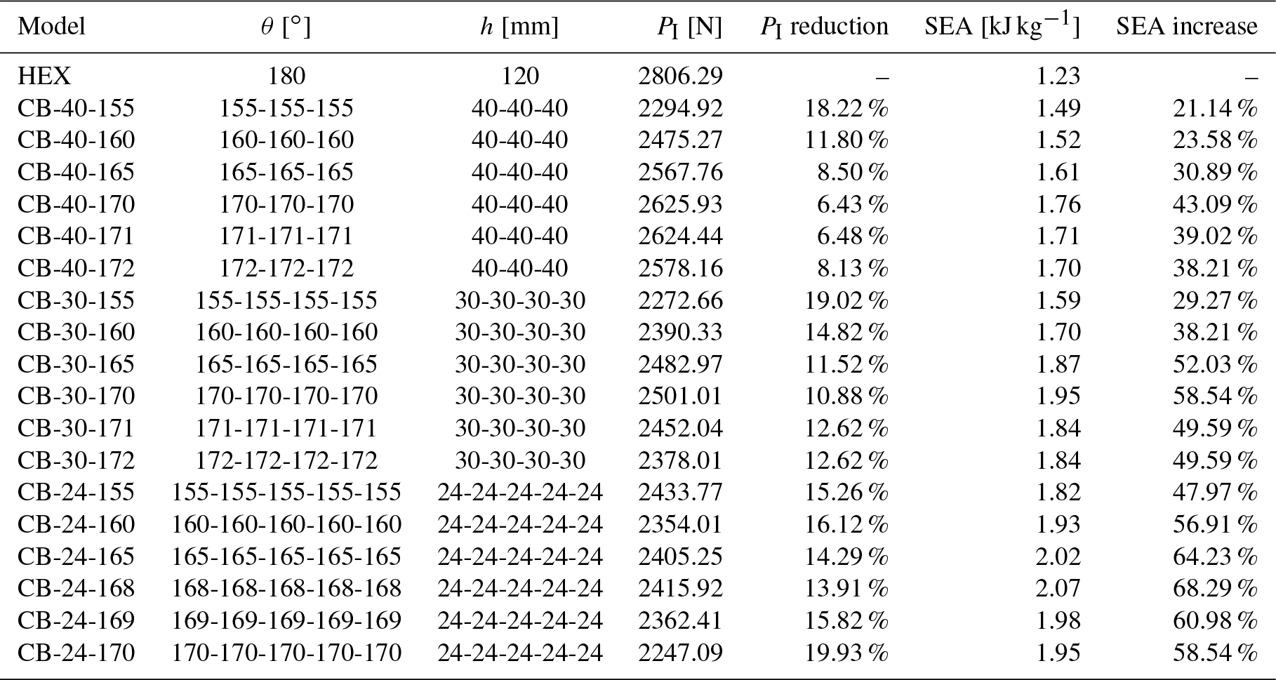
A multi-layer crash box can be built by stacking several layers axially as long as the side length is constant. On the other hand, the layer height and pre-folding angle, can be different from layer to layer, which creates a tube with graded geometric properties. For instance, a five-layer crash box with varying layer height is shown in Fig. 1c. To evaluate the effect of these geometric parameters on the deformation mode and the energy absorption performance, a total of 18 uniform and 8 graded models were designed and analyzed. The pre-folding angle θ and layer height h were varied while keeping tube height H=120 mm, side length b=40 mm and wall thickness t=0.3 mm constant. Furthermore, we built a benchmark conventional hexagonal tube with identical H, b and t. The geometric details are summarized in Tables 1 and 2. It is worth noting that CB-h-θ is for uniform origami crash boxes and CB-g is for geometrically graded boxes. The initial peak force, PI, defined as the first peak force, and the Specific Energy Absorption (SEA), defined as the energy absorption per unit mass (Lu and Yu, 2003) are also presented in the tables, which will be discussed later in the paper. The following equation is used to calculate SEA
where m is the mass of the model and δ is the crushing displacement.
3.1 Specimen fabrication
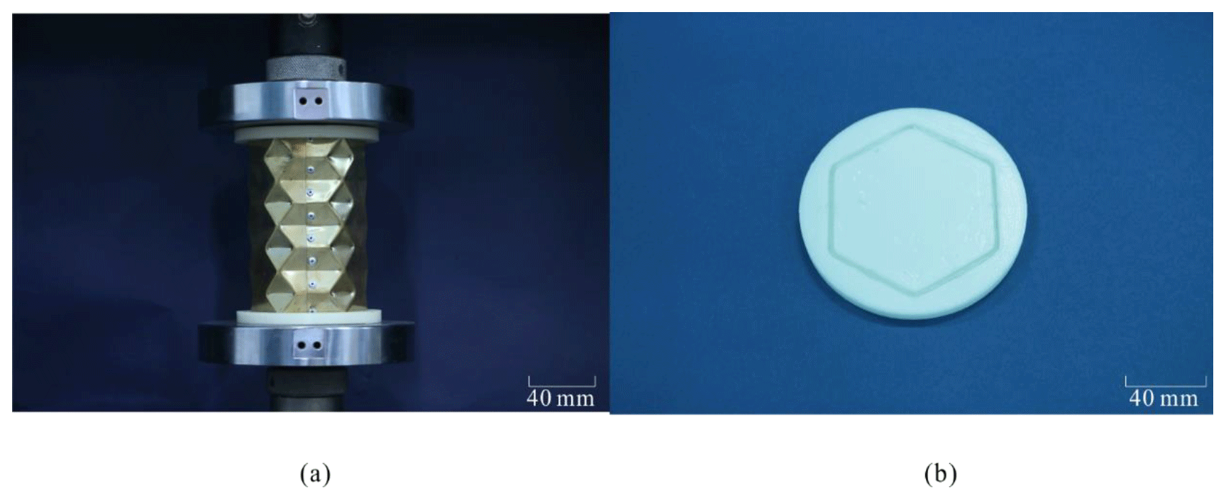
Brass (CuZn40) origami crash box CB-30-155 with a thickness of 0.3 mm was fabricated through a four-step process. As illustrated in Fig. 2, the fabrication procedures are as follows: (1) The brass sheet was first stamped using a pair of male and female molds (as shown in panels a, b). The molds are printed by “Three Dimension Elite” machine using ABS (Acrylonitrile Butadiene Styrene) plastic. Protruded steel bars and rubber strips were used to generate crease patterns by placing them on the molds, which included two types of grooves: that was, 5 mm wide by 3 mm deep (for rubber strips), and 2 mm wide by 1 mm deep (for steel bars). The width and thickness of the rubber stripes were 5 and 3 mm, respectively, and the radius of the steel bars was 1 mm. At the end of this step, we can get a series of well-shaped mountain and valley creases as shown in panel (c). (2) Then, the sheet was folded along the creases to form a half-tube using the forming mold. This mold is also 3-D-printed, which is shown in panel (d). (3) Thirdly, two half-tubes were connected by eight riveting spots with an overlapped width of 5 mm. The finished origami crash box can be found in panel (e). (4) As a final point, in order to release the residual stress created during folding (Ding et al., 1992), the specimen was then heat treated for 8 min at a temperature of 500 ∘C. Similarly, conventional hexagonal tube (referred as HEX hereafter), shown in panel (f), was also assembled and heat treated following the same procedure above.

Figure 2Fabrication of origami crash box samples: (a) male mold; (b) female mold; (c) a patterned sheet after stamping; (d) a half-tube mold by 3-D printing; (e) a completed origami crash tube; (f) a conventional hexagonal tube.
3.2 Experimental setup
A quasi-static axial crushing test was thus performed with the experimental setup shown in Fig. 3. The tube was inserted between two plates with 8 mm thickness, which included hexagonal grooves of 3 mm wide and 2 mm deep. The specimen was constrained by the grooves at both ends and compressed under displacement control with the loading rate of 5 mm min−1. Three specimens were tested for each design case with the prescribed displacement of 80 mm. In addition, the complete sequence of the crushing and folding was monitored and recorded.
The FE model developed by Abaqus/Explicit was used to simulate the axial crushing of origami crash box (Abaqus Manual, 6.14-1, 2014). The tube was placed between two rigid plates. The top and bottom edges of the tube were pinned to the plates. The bottom plate was fixed in space while the top one was displaced downward incrementally. The tube was meshed with linear shell element S4R, with five integration points through the thickness. Self-contact, as well as surface-to-surface contact, were defined with hard contact conditions. The friction coefficient was set to be 0.3.
The material strength was measured by conducting tensile tests of test coupon (ISO 6892-1, 2016). The main mechanical properties were: density ρ=8.33 g cm−3, Young's modulus E=109.14 GPa, yield stress σy=103.99 MPa, tensile strength σu=454.08 MPa, and elongation εu=35.9 %.
Convergence tests concerning mesh density and analysis time were conducted respectively. To get rid of the hour-glassing effect, the ratio of artificial energy to internal energy was controlled to be less than 5 %. In addition, we also make sure the ratio of kinetic energy to internal energy was below 5 %. It was found that a global mesh size of 1 mm and an analysis time of 0.2 s yielded reasonable results.
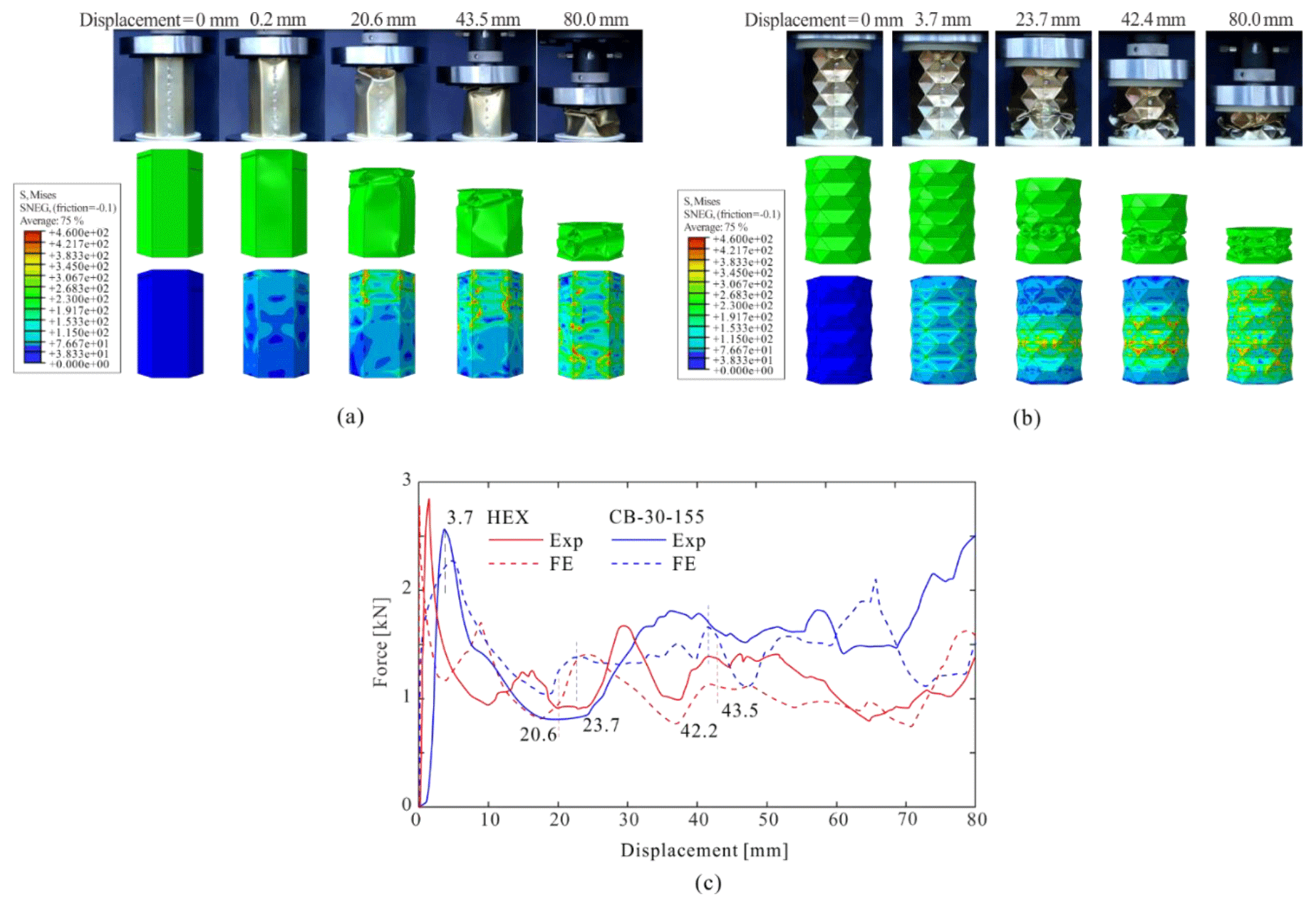
Figure 4The crushing process of HEX and CB-30-155: (a) the deformation process of HEX; (b) the deformation process of CB-30-155; (c) experimental and numerical force versus displacement curves of HEX and CB-30-155.
5.1 Crushing progression of representative tubes
The crushing progress, as well as the recorded axial force-displacement responses, are provided in Fig. 4. Qualitatively good agreement can be found between the experiments and the numerical simulation for both HEX and CB-30-155. The minor discrepancy mainly stems from the inconsistency of the specimens' dimension with that of the FE model, as well as the existence of geometric imperfections. Since the present study focuses on the overall energy absorption performance, these factors are not examined in detail at this moment. Overall, the difference in the SEA of the conventional hexagonal tube is 8.11 %, and CB-30-155 is 6.81 %. The sequences of deformed configurations are shown in the top row (the green images), and for better observations of high-stress regions, the undeformed shapes with von Mises stress color contours are also included at the bottom. The evolution of crushing and folding shown in Fig. 4b proves the consistency between the experiments and numerical simulation as well. Upon compression, the tube first deforms following the built-in crease pattern, and then localization starts to take place at the weakest part of the structure. With increasing compression, the localized deformation develops into a band which flattens and exhausts the whole layer. At some higher strain, the crushed zone progressively moves to adjacent layers, which eventually collapses the entire structure.
Regarding the axial force-displacement response, as shown in Fig. 4c, there exhibits a high peak at the beginning of the loading, and then it is followed by several periodic fluctuations at higher strain levels, which corresponds to the gradual spread of crushing zones. Comparing with the results of HEX, the origami crash box clearly reduces the initial peak force while raising the following fluctuation level. The elevated overall force level, in turn, increases the total energy absorbed. These unique advantages brought along with origami patterns are highly desirable traits for energy absorption devices. The PI of CB-30-155 is found to decrease by 19.02 %, and the SEA to increase by 29.27 %. Table 1 lists the detailed results of the initial peak force PI and the specific energy absorption (SEA).
In summary, the results clearly show that the introduction of origami crease pattern can effectively help improve the energy absorption performance.
5.2 Effect of pre-folding angle
5.2.1 Uniform pre-folding angle
The pre-folding angle θ determines the extent to which a tube is pre-folded. As reported in earlier research (Song et al., 2012), there is a critical θ: when the pre-folding angle passes the critical value, the failure mode will not follow the crease pattern. Thus, we analyzed a group of uniform models with three different h and θ to better understand this phenomenon.
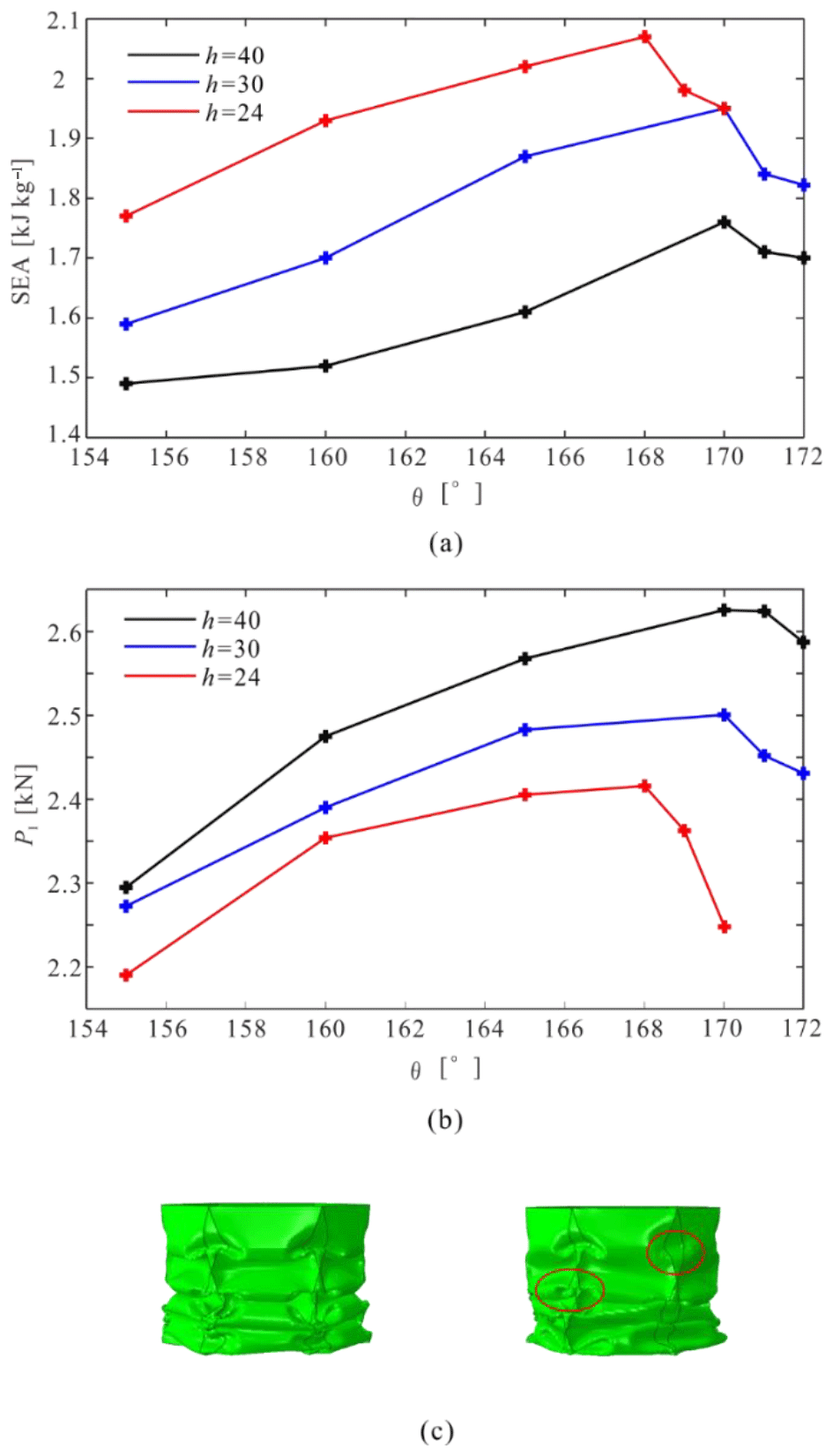
Figure 5Effect of uniform pre-folding angles. (a) SEA versus θ curves; (b) PI versus θ curves; (c) deformed configurations of models CB-30-170 and CB-30-171.
The geometric parameters and the corresponding results are listed in Table 1, and the SEA and PI are plotted against θ in Fig. 5. It can be found that the absorbed energy and the peak force initially increase linearly with θ, and then develop a maximum after reaching a critical value. For h=30 mm cases, the critical θ is 170∘. This can be attributed to the fact that once θ surpasses the critical value the deformation evolution will no longer follow the designed creases, which in turn will undermine its energy absorbing performance. Shown in Fig. 5c are the crushed configurations of CB-30-170 and CB-30-171, with θ right in the neighborhood of this critical value. Similarly, the same trend also exhibits for h=40 mm and h=24 mm cases – the critical θ is 170∘ for the former case and 168∘ for the latter one. Model CB-24-168, which is found to be an optimal case for the uniform angle design, achieves an improvement of 68.29 % increase in the SEA and 13.91 % reduction in the initial peak force.
5.2.2 Graded pre-folding angle
Graded pre-folding angle design changes the structural uniformity in the stacking direction and we thus further study the effect of pre-folding angle variation among the layers. CB-24-155 crease pattern was selected as the base case to create CB-g1 to CB-g3 models. The detailed θ layout is listed in Table 2. It is worthwhile to point out that the θ in all the models are below the critical value of 168∘.
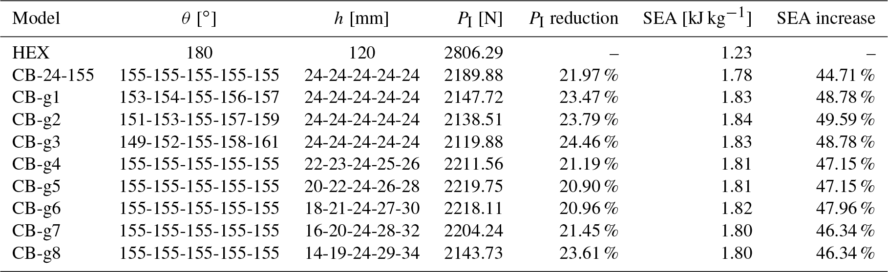
Table 2Geometrical parameters and numerical results of graded origami crash boxes.
The deformed and the undeformed configurations with von Mises stress color contour of CB-g2 are presented in Fig. 6a as a representative example. Like the base case, the sequence of crushing and folding followed the designed creases progressively. The axial force-displacement responses in Fig. 6b show that the initial peak force is reduced slightly although the following periodic local peaks are altered due to the change of crushing path. On the other hand, the SEA remains nearly identical despite the graded θ. The detailed results are summarized in Table 2. Overall, the origami crash box with graded pre-folding angle design possesses satisfactory energy absorption performance, similar to the uniform model. Its performance is found to be not very sensitive to the variation of θ, at least in the range of parameter change conducted in this study. However, the graded pre-folding angle design can readily be used to control the crushing zone and the crushing path for the origami crash box.

Figure 6Effect of graded pre-folding angles. (a) The deformation process of CB-g2; (b) force versus displacement curves of HEX, CB-24-155, and CB-g2.
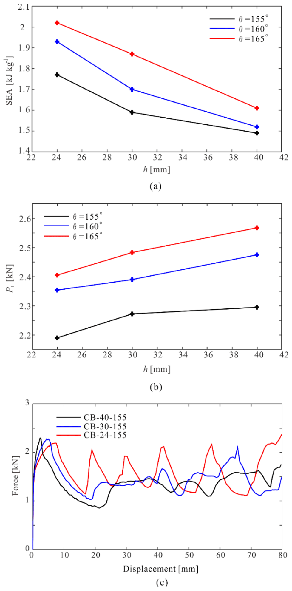
Figure 7Effect of layer heights in uniform models. (a) SEA versus layer height curves; (b) PI versus layer height curves; (c) force versus displacement curves of model CB-40-155, CB-30-155 and CB-24-155.
5.3 Effect of layer height
5.3.1 Uniform layer height
The height of each stacking layer is expected to affect the energy absorption performance, and thus a group of uniform models with varying unit heights were built. Nine cases with 155, 160 and 165∘ pre-folding angle were analyzed. The SEA and PI results are plotted against h in Fig. 7a and b and provided in Table 2. Apparently, as the unit height increases, the absorbed energy drops, while the peak force is seen to increase. In other words, smaller h, which leads to more layers for a fixed length, results in higher energy absorption and lower and more uniform local peaks (Fig. 7c), and therefore more suitable for energy absorption devices.
5.3.2 Graded layer height
We now further study the effect of the graded height of stacking layers alike. Model CB-24-155 was designated as the base case to create CB-g4 to CB-g8 models. The height of the unit layer varies from 14 to 34 mm while maintaining θ=155∘ constant. The geometric details and the summary of results are listed in Table 2. Additionally, the sequence of deformed configurations of CB-g6 is presented in Fig. 8a with the color contour representing von Mises stresses. Similarly, the crushing and folding of the tube follow the designed crease pattern. Figure 8b shows the axial force-displacement responses of the base case and CB-g6, which indicates that the variation of unit layer height only results in some shift of periodic local peaks, but not the initial peak force. Likewise, the change of the SEA is also found to be not very significant. In other words, the graded layer height design is as good as the uniform height design regarding the energy absorption performance, even though its performance is not very sensitive to the variation of unit layer height.
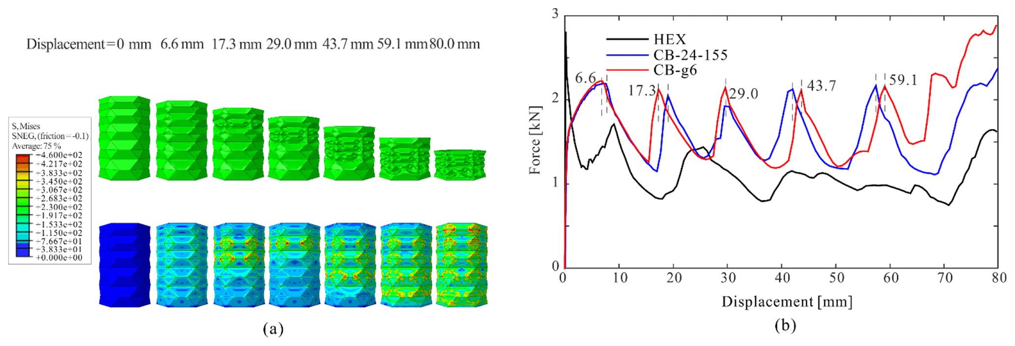
Figure 8Effect of graded layer height. (a) The deformation process of CB-g6; (b) force versus displacement curves of HEX, CB-24-155, and CB-g6.
The preceding sections have demonstrated that the energy absorption performance of origami crash boxes outweighs that of conventional hexagonal tubes. Also, the initial peak force and absorbed energy can be optimized through the control of critical geometric parameters. Thus, to better facilitate engineering applications, we derive a theoretical solution to calculate its energy absorption.
Consider a basic folding element which consists of one corner of a crash box layer with side length b, layer length l and corner width c. The crushing process can be approximately divided into two stages for the basic folding element. At stage I, CA1, CB1, EA1, EB1, highlighted by thick red lines in Fig. 9a, become traveling plastic hinge lines and move away from the corner as the element is being crushed until they reach CA, CB, EA, EB, respectively. The value of α can be measured from the numerical models, and it is around 45∘. In the meantime, a circumferential stationary plastic hinge line, which is also highlighted by the thick line, takes place in the middle section and is continuously bent during the propagation of traveling plastic hinge lines. The configuration of the element at the end of stage I is shown in Fig. 9b. At stage II, more plastic hinge lines show up: four inclined stationary plastic hinge lines, FA, FB, GA, and GB; two vertical ones, FC, GE; and two circumferential ones passing points F and G. These plastic hinge lines are highlighted by thick lines in Fig. 9c. With the increasing bending, the basic folding element is crushed entirely at the end. Similarly, the angle β found to be around 15∘. The final folded configuration is shown in Fig. 9d. By summing up the energies absorbed at stages I and II, the total energy absorption can be calculated.
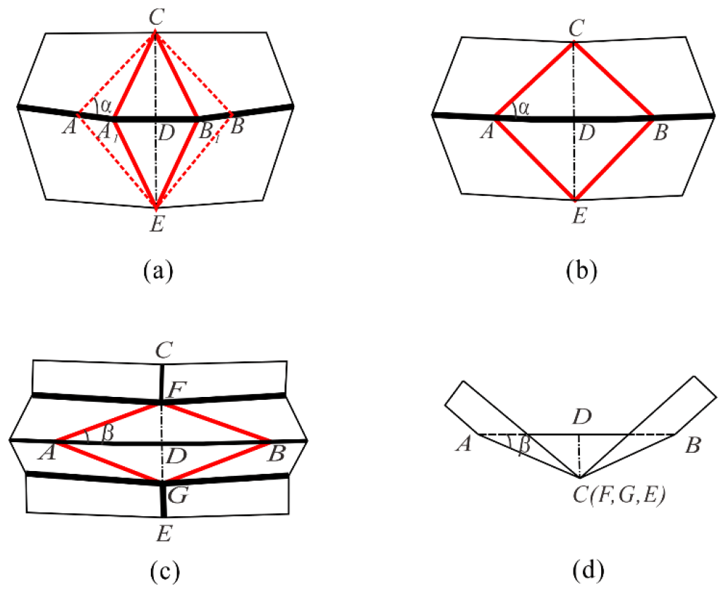
Figure 9Crushing process of the basic folding element. (a) Perspective view of the initial configuration; (b) perspective view of the configuration at the end of stage I; (c) perspective view of a partially crushed configuration at stage II; (d) top view of the entirely crushed configuration.
As indicated by Meng's previous study (Meng et al., 1983), when a traveling plastic hinge line swept an area, the material was bent to a radius r and then flattened back. Additionally, around the intersecting point of two traveling plastic hinge lines, there existed the in-plane deformation in the localized zone (Wierzbicki and Abramowicz, 1983), like A1 and B1 in Fig. 9a. In light of this theory, the energy of the first stage can be thus divided into three parts: (1) the circumferential stationary plastic hinge line; (2) the inclined traveling plastic hinge lines; and (3) the in-plane deformation. The stationary plastic hinge line will be included at stage II considering the continuous bending during the entire crushing process.
To obtain the energy absorption of the traveling plastic hinge line, we first consider hinge line CA1 only. Here CA1 travels from its original position until it reaches CA, sweeping the area of triangle ACA1. For simplicity, it is assumed that the bending and unbending radius r is constant and r≪b. Therefore, the energy absorbed by CA1 is
where Mp is the full plastic bending moment per unit length (Abramowicz and Wierzbicki, 1989) and σ0 is the effective plastic flow stress (Santosa et al., 2000), which can be calculated as
Consider that there are four traveling plastic hinge lines in one element, the energy absorbed by this part is
For the energy absorption of the in-plane deformation, the energy dissipated at one intersecting point is
Where I1 is a numerical integral.
Since there are two intersecting points in the element, the energy absorbed by this part is
The energy absorption at stage II can be obtained by summing up the energies absorbed by the three circumferential stationary plastic hinge lines, four inclined ones and two vertical ones. These three circumferential hinge lines have identical length b, and their angles of rotation from top to bottom are , respectively. Therefore, the energy absorbed by this part is
Besides that, the total length of the four inclined hinge lines is
And their angle of rotation is π, so the energy absorbed by this part is
The total length of the two vertical hinge lines is
And their angle of rotation is , so the energy absorbed by this part is
Subsequently, the mean crushing force can be calculated by applying the balance between external work and internal plastic dissipation. Considering that there are six basic folding elements in a module, the following equation could be obtained.
Substituting Eqs. (10), (13), (14), (16), (18) into Eq. (19) yields
Parameter r should be chosen to make a minimum. Taking the derivative of Eq. (20) with respect to r,
which yields
Solving r, which is
Substituting Eqs. (8) and (23) into Eq. (20), we obtain
For a multi-layer crash box, the energy absorption of each layer can be calculated from Eq. (25), and the mean crushing force can be obtained from the following equation.
in which and lj are respectively the mean crushing force and length of layer j, and k is the number of layers in a crash box.
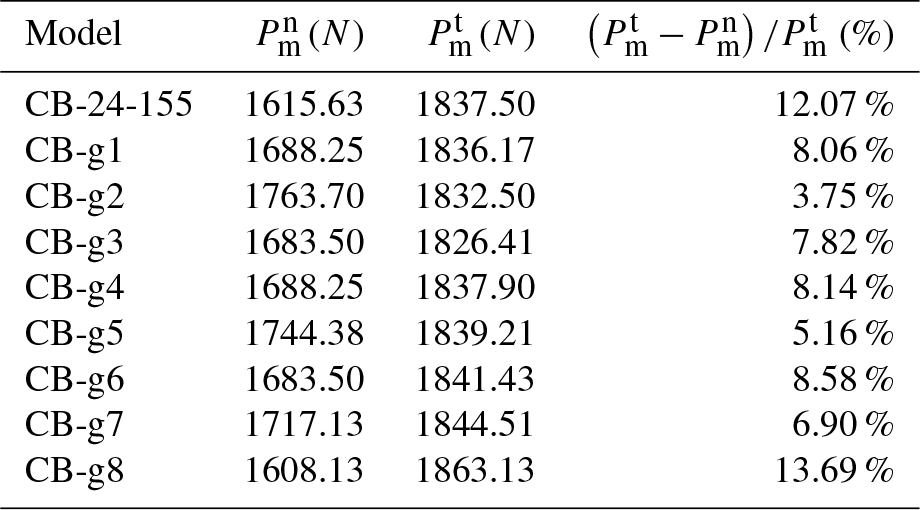
It's worth pointing out that the crushing distance is only nearly 30 % of its overall height based on the basic folding element. However, this value can reach around 70 % for an average thin-walled tube. Therefore, we adjusted the final crushing distance in the equation for the mean crushing force calculation. Consequently, we calculated the mean crushing force of CB-24-155 and all the graded models and listed in Table 3. The numerical value of the mean crushing force, , of all the model are also obtained through the following equation and listed in Table 3.
Overall, a good match between theoretical and numerical results are obtained. With the theoretical equation, it is possible to select the geometry and material of the crash box based on the specific requirement of energy absorption. Both uniform and graded structures can be designed based on the theoretical equation.
In this paper, the quasi-static axial crushing behavior of a hexagonal energy absorption device named the origami crash box is studied through experiments, numerical simulation, as well as theoretical analysis. The proposed origami pattern is found to be able to trigger a diamond-shaped mode. More importantly, this design successfully achieved two objectives: lower initial peak force and higher energy absorption. Sensitivity study of the pre-folding angle θ and layer height h are conducted. It is found that when the crash box has a uniform geometry, increasing θ and reducing h could both lead to an improvement in energy absorption, provided that θ is below a critical value to ensure that the crease pattern is well followed. In the case of graded structures, which possess varying geometric parameters among layers, the local peaks of the reaction force can be shifted, but the overall energy absorption performance is not significantly changed. Subsequently, we propose a theoretical solution for the axial crushing energy absorption based on the introduction of a basic folding element. The accuracy of this solution is further validated by good agreements between its prediction and the numerical simulation. Therefore, it can be used to assist design optimization when various geometric parameters and materials are involved.
The dynamic behavior of the origami crash box is also of great practical significance and will be examined as the next effort. Moreover, the current theoretical solution tends to overestimate the energy absorption of the origami crash box, which also needs further investigation.
The data can be made available upon request. Please contact Lin Yuan via lin_yuan@tju.edu.cn.
HD and MS conducted the specimen fabrication and experiment. JM and LY suggested the overall concept of this paper and built the FEM model as well as the theoretical solution. YC and ZY verified the proposed theoretical model with the experiments and supervised the whole project.
The authors declare that they have no conflict of interest.
Yan Chen acknowledges the support of the National Natural Science Foundation of China (Projects 51825503, 51721003), Jiayao Ma acknowledges the support of the National Natural Science Foundation of China (Project 51575377), and Zhong You acknowledges the support of the Air Force Office of Scientific Research (FA9550-16-1-0339). During this research, Zhong You was appointed as a visiting professor at Tianjin University. Some of the preliminary results were presented at ASME 2018 IDETC/CIE conference in Quebec, Canada, and appeared in the conference proceeding Ref. (Shi et al., 2018).
This paper was edited by Guimin Chen and reviewed by two anonymous referees.
Abaqus Manual: Dassault Systems SIMULA Corp. Abaqus Analysis User's Manual, Abaqus documentation Version 6.14-1, Providence, RI, USA, 2014.
Abramowicz, W.: The effective crushing distance in axially compressed thin-walled metal columns, Int. J. Impact Eng., 1, 309–317, https://doi.org/10.1016/0734-743X(83)90025-8, 1983.
Abramowicz, W. and Jones, N.: Dynamic axial crushing of square tubes, Int. J. Impact Eng., 2, 179–208, https://doi.org/10.1016/0734-743X(84)90005-8, 1984.
Abramowicz, W. and Jones, N.: Dynamic progressive buckling of circular and square tubes, Int. J. Impact Eng., 4, 243–270, https://doi.org/10.1016/0734-743X(86)90017-5, 1986.
Abramowicz, W. and Wierzbicki, T.: Axial crushing of multicorner sheet metal columns, J. Appl. Mech., 56, 113–120, https://doi.org/10.1115/1.3176030, 1989.
Airoldi, A. and Janszen, G.: A design solution for a crashworthy landing gear with a new triggering mechanism for the plastic collapse of metallic tubes, Aerosp. Sci. Technol., 9, 445–455, https://doi.org/10.1016/j.ast.2005.04.001, 2005.
Alexander, J. M.: An approximate analysis of the collapse of thin cylindrical shells under axial loading, Q. J. Mech. Appl. Math., 13, 10–15, https://doi.org/10.1093/qjmam/13.1.10, 1960.
Ding, H., Wu, Q., and Ma, L.: Deformation behaviour in α∕β two-phase super-plastic brass, J. Mater. Sci., 27, 607–610, 1992.
Fan, Z., Lu, G., and Liu, K.: Quasi-static axial compression of thin-walled tubes with different cross-sectional shapes, Eng. Struct., 55, 80–89, https://doi.org/10.1016/j.engstruct.2011.09.020, 2013.
Guillow, S. R., Lu, G., and Grzebieta, R. H.: Quasi-static axial compression of thin-walled circular aluminum tubes, Int. J. Mech. Sci., 43, 2103–2123, https://doi.org/10.1016/S0020-7403(01)00031-5, 2001.
ISO 6892-1 (International Organization for Standardization): Metallic materials-tensile testing-part 1: method of test at room temerature, ISO 6892-1:2016, International Organization for Standardization, Geneva, 2016.
Lu, G. and Yu, T.: Energy Absorption of Structures and Materials, CRC, Boca Raton, FL, USA, 2003.
Ma, J. and You, Z.: Energy absorption of thin-walled square tubes with a pre-folded origami pattern – Part I: geometry and numerical simulation, J. Appl. Mech., 81, 011003, https://doi.org/10.1115/1.4024405, 2014.
Ma, J., Hou, D., Chen, Y., and You, Z.: Quasi-static axial crushing of thin-walled tubes with a kite-shape rigid origami pattern: Numerical simulation, Thin Wall. Struct., 100, 38–47, https://doi.org/10.1016/j.tws.2015.11.023, 2016.
Mamalis, A. G., Viegelahn, G. L., Manolakos, D. E., and Johnson, W.: Experimental investigation into the axial plastic collapse of steel thin-walled grooved tubes, Int. J. Impact Eng., 4, 117–126, https://doi.org/10.1016/0734-743X(86)90012-6, 1986.
Mamalis, A. G., Manolakos, D. E., Baldoukas, A. K., and Viegelahn, G. L.: Energy dissipation and associated failure modes when axially loading polygonal thin-walled cylinders, Thin Wall. Struct., 12, 17–34, https://doi.org/10.1016/0263-8231(91)90024-D, 1991.
Mamalis, A. G., Manolakos, D. E., Ioannidis, M. B., Kostazos, P. K., and Dimitriou, C.: Finite element simulation of the axial collapse of metallic thin-walled tubes with octagonal cross-section, Thin Wall. Struct., 41, 891–900, https://doi.org/10.1016/S0263-8231(03)00046-6, 2003.
Martinez, E., Tyrell, D., and Perlman, A. B.: Development of crash energy management designs for existing passenger rail vehicles, 2004 ASME International Mechanical Engineering Congress and Exposition, 13–19 November 2004, Anaheim, CA, USA, https://doi.org/10.1115/IMECE2004-61601, 2004.
Meng, Q., Al-Hassani, S. T. S., and Soden, P. D.: Axial crushing of square tubes, Int. J. Mech. Sci., 25, 747–773, https://doi.org/10.1016/0020-7403(83)90080-2, 1983.
Rossi, A., Fawaz, Z., and Behdinan, K.: Numerical simulation of the axial collapse of thin-walled polygonal section tubes, Thin Wall. Struct., 43, 1646–1661, https://doi.org/10.1016/j.tws.2005.03.001, 2005.
Santosa, S. P., Wierzbicki, T., Hanssen, A. G., and Langseth, M.: Experimental and numerical studies of foam-filled sections, Int. J. Impact Eng., 24, 509–534, https://doi.org/10.1016/S0734-743X(99)00036-6, 2000.
Shi, M., Ma, J., Chen, Y., and You, Z.: Energy Absorption of Origami Crash Box: Numerical Simulation and Theoretical Analysis, in: Proceedings of 42nd Mechanisms and Robotics Conference, 26–28 August 2018, Quebec, Canada, https://doi.org/10.1115/DETC2018-86261, 2018.
Singace, A. A. and El-Sobky, H.: Behaviour of axially crushed corrugated tubes, Int. J. Mech. Sci., 39, 249–268, https://doi.org/10.1016/S0020-7403(96)00022-7, 1997.
Song, J., Chen, Y., and Lu, G.: Axial crushing of thin-walled structures with origami patterns, Thin Wall. Struct., 54, 65–71, https://doi.org/10.1016/j.tws.2012.02.007, 2012.
Tyrell, D., Jacobsen, K., Martinez, E., and Perlman, A. B.: A train to train impact test of crash energy management passenger rail equipment: structural results, 2006 ASME International Mechanical Engineering Congress and Exposition, 5–10 November 2006, Chicago, Illinois, USA, 2006.
Wierzbicki, T. and Abramowicz, W.: On the crushing mechanics of thin-walled structures, J. Appl. Mech., 50, 727–734, https://doi.org/10.1115/1.3167137, 1983.
Wierzbicki, T., Bhat, S. U., Abramowicz, W., and Brodkin, D.: Alexander revisited – a two folding elements model of progressive crushing of tubes, Int. J. Solids Struct., 29, 3269–3288, https://doi.org/10.1016/0020-7683(92)90040-Z, 1992.
Wu, S., Li, G., Sun, G., Wu, X., and Li, Q.: Crashworthiness analysis and optimization of sinusoidal corrugation tube, Thin Wall. Struct., 105, 121–34, https://doi.org/10.1016/j.tws.2016.03.029, 2016.
Yang, K., Xu, S., Shen, J., Zhou, S., and Xie, Y. M.: Energy absorption of thin-walled tubes with pre-folded origami patterns: Numerical simulation and experimental verification, Thin Wall. Struct., 103, 33–44, https://doi.org/10.1016/j.tws.2016.02.007, 2016.
Yang, Y., Nara, C., and Hagiwara, I.: Energy absorption characteristics of pairing origami structure, in: Proceedings of the Dynamics and Design Conference, 23–26 August 2016, Yamaguchi-ken, Japan, https://doi.org/10.1299/jsmedmc.2016.526, 2016.
Yang, Z., Yu, T., Wei, Y., and Huang, C.: Crushing behavior of a thin-walled circular tube with internal gradient grooves fabricated by SLM 3D printing, Thin Wall. Struct., 111, 1–8, https://doi.org/10.1016/j.tws.2016.11.004, 2017.
Zhang, X. and Zhang, H.: Experimental and numerical investigation on crush resistance of polygonal columns and angle elements, Thin Wall. Struct., 57, 25–36, https://doi.org/10.1016/j.tws.2012.04.006, 2012.