the Creative Commons Attribution 4.0 License.
the Creative Commons Attribution 4.0 License.
 | 04 Feb 2026
Research on the mechanism of metro wheel high-order polygons affecting sound pressure level
Jianhui Tian
This paper analyses the effects of several typical polygon amplitudes and orders on wheel sound radiation in metro lines using the finite-element method (FEM) and the boundary element method (BEM). A vehicle–rail coupled rolling contact model incorporating wheel polygons is established, and the wheel–rail forces under different polygon amplitudes and orders are obtained. The corresponding wheel sound radiation results are also obtained. The results demonstrate that the model accurately reflects the impact of polygons on wheel–rail forces. Polygons increase inter-wheel–rail forces, and higher polygon orders result in greater wheel–rail forces for both standard and resilient wheels. However, the wheel–rail forces do not exhibit a linear relationship with polygon amplitude. Furthermore, the noise reduction mechanism of resilient wheels is thoroughly explained in terms of damping, energy dissipation, vibration isolation, decoupling, and acoustic impedance characteristics. By changing the polygon amplitude, order, and track line, it was found that, within the 400–5000 Hz frequency range, the higher the polygon orders, the higher the sound pressure level (SPL) for two types of wheels. Polygon amplitudes differ, with the resilient wheels radiating SPL 2–13 dB(A) lower than the standard wheels in the 2500–5000 Hz frequency range. No significant linear relationships were found between the polygon amplitude and the SPL of the two types of wheels in most frequency bands. Additionally, the SPL of the resilient wheels is 3–10 dB(A) lower than that of the standard wheels in the 2500–5000 Hz band under curve conditions. Moreover, under curve conditions the rubber layer of the resilient wheels reduces the SPL at a high speed and frequency.
- Article
(1037 KB) - Full-text XML
- BibTeX
- EndNote


As train operation speeds and mileage increase, wheel polygons (the shape of uniform wear superposed around the circumference surface) are becoming a more serious issue. Higher-order polygons cause high-frequency vibrations in the wheel–rail system, generating strong wheel–rail noise (Wang et al., 2020a). In-vehicle noise is caused by wheel out of roundness, and investigations have found that most wheels exhibit severe polygonal wear (uniform wear superposed around the circumference surface). To improve ride comfort and control in-vehicle noise interference, it is essential to study the formation mechanism of wheel scuffing. Wheel polygonal wear is a common phenomenon in the railway industry that exacerbates wheel–rail interactions (Yang et al., 2022) and causes premature failure of or damage to components of the vehicle–rail system (Wang et al., 2020b; Wu et al., 2019, 2016). Tao et al. (2020) reviewed current research on wheel wear and identified future research priorities.
In recent years, scholars have conducted extensive research on wheel–rail high-frequency vibration and noise. Nielsen (2009) investigated different types of wheel out of roundness and simulated the effects of wheel–rail contact force and vehicle–rail response under wheel out-of-roundness conditions. Wu et al. (2018) analysed the relationship between wheel polygonal wear and wheel–rail force. They used time-domain wheel–rail force as an external excitation to analyse the effect of wheel polygonal wear on the vibration response of the bogie axlebox and frame. Song et al. (2017, 2022) used ANSYS and SIMPACK software to create a model of the dynamics of a rigid–flexible vehicle coupling system, studied the factors influencing the development of wheel polygons in high-speed trains, and proposed a limit value for wheel polygons. Research into wheel–rail noise was primarily based on the models of Remington (1976a, b) and Thompson (1993, 2008) in the early years. The European Railway Research Institute developed the TWINS noise prediction model (Thompson et al., 1996a, b), which remains the most accurate model for calculating wheel–rail rolling noise to date. Zhou et al. (2024) and Cheng et al. (2021) researched the impact of the new wheel design on noise level. He et al. (2022, 2023) researched the effect of resilient wheels on vibration and noise. Wei et al. (2022) researched carriage interior noise. However, the above results have only investigated the effect of wheel out of roundness on abnormal vehicles and rail vibration, while the effect on noise has not been analysed in detail. Although scholars have conducted extensive research on wheel polygons, little research has been conducted on their relationship with noise. As testing technology and theoretical simulation continue to progress, it will be possible to conduct an in-depth study of the mechanism of noise generated by wheel polygons. Sound pressure level (SPL) is a unit used to describe sound intensity. It represents the logarithmic ratio of sound pressure (the pressure variation of sound waves) relative to a reference pressure. It reflects the loudness of sound and is used to evaluate noise environments. Wu and Thompson (2003) proposed a hybrid calculation method for wheel–rail contact nonlinearity. This method calculates the wheel–rail impact force in the time domain and then converts it into a frequency-domain force, which is used as input for frequency-domain sound radiation calculations. However, although this method considers nonlinear contact, it is only suitable for lower-frequency analysis and cannot be used for high-frequency analysis.
Owing to the severe effects of wheel high-order polygons on wheel–rail interactions and noises, it is important to establish a thorough understanding of these effects. With the continuous growth in demand for research on high-frequency conditions, gaining a deeper understanding of the influence mechanisms of curved and straight conditions on wheel–rail forces and noises is also crucial. This paper established a rolling noise calculation model for wheels and rails, using finite-element and boundary element methods. The nonlinearity of wheel–rail contact is taken into account in the rolling contact model based on the finite-element method through the introduction of the vehicle–rail coupled rolling contact model. The high-frequency interaction force between the wheel and rail and the corresponding acoustic radiation within 5000 Hz of the wheel polygon are computed under conditions of different polygon amplitudes and orders, as well as under curved and straight conditions. This provides a reference for the study of metro SPL.
This section establishes a vehicle–rail coupled rolling contact model and a model of predicting vibration and sound radiation from wheels and rails. Through numerical calculations, the effects of wheel polygon amplitudes and orders on wheel–rail forces and noise are investigated.
2.1 Dynamic modelling of wheel–rail rolling contact
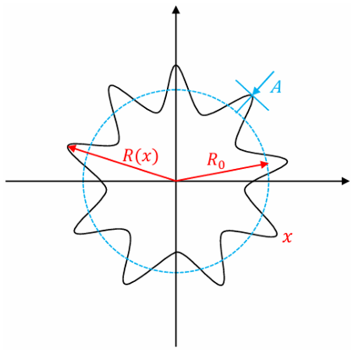
Based on the frequently occurring wheel polygon situation, this paper considers the following orders: the third order, fifth order, seventh order, and ninth order, as well as wheel polygon amplitude A (0.01, 0.03, 0.05, and 0.07 mm), shown in Fig. 1. The design of the wheel, the condition of the rail, the operating environment, and the wear mechanisms result in the frequent occurrence of these four distinct orders of polygons. Furthermore, the higher the order of the polygon, the greater the number of contact points between the wheel and the rail. Wheel polygon orders are divided according to the development speed of the wheel–rail vertical force. Orders 1–5 are in the region of less influence, while orders 6–9 are in the region of smooth growth. The ninth-order wheel polygon is very common in field measurements and is used as an example here. Figure 1 is a schematic diagram of the ninth-order wheel polygon.
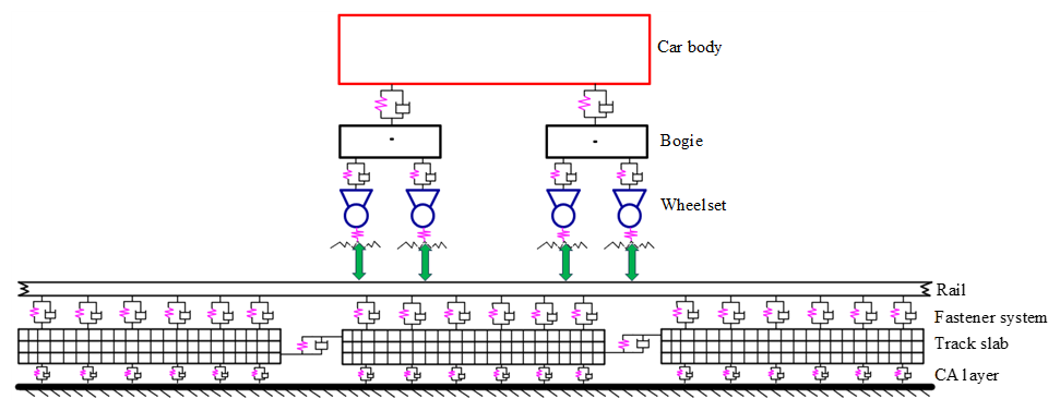
To study wheel–rail vibration and the vertical force caused by wheel polygons, the out-of-roundness and radial deviation of the wheel tread are transformed into inhomogeneous wheel–rail contact surface displacement, then input into the vehicle–rail coupled rolling contact model. The vehicle–rail coupled rolling contact model is shown in Fig. 2 and can accurately predict the noise that occurs under wheel polygon conditions when combined with the conventional unballasted track.
The radial deviation of the wheel is expressed as follows (Song et al., 2023):
In Eq. (1), x represents the circumference of the wheel, R(x) represents the actual radius of the wheel, and R0 represents the nominal radius of the rolling circle. The following is in polar coordinate form:
In Eq. (2), θ is the angle on the wheel's circumference. Δr(θ) is the radial deviation of the wheel and can be expanded into a Fourier series with multiple harmonics:
In Eq. (3), Ai is the amplitude of the ith harmonic, and φi is the corresponding phase.
The wheel radial deviation Δr(θ) is unfolded periodically and transformed into the time course of wheel–rail upset, denoted as follows:
Assuming that the train operates at speed v (m s−1), that the nominal wheel a has a radius R, and that the wheel has Nth-order polygonal wear, the excitation frequency of the vehicle is given by the following formula:
Na is the polygon order of wheel a, while Ra is the radius of wheel a. The relationship between Na, Ra, and the vehicle excitation frequency f can then be written as follows:
2.2 Model of predicting vibration and sound radiation from wheel and rail
The steady-state sound pressure at any point in the spatial sound field is determined by the second-order Helmholtz equation:
where k is the wave number, c is the speed of sound, ω is the angular frequency, and f is the frequency.
Once the boundary conditions are specified, the solution of the Helmholtz equation (Eq. 7) is unique. The boundary conditions of the external acoustic field consist of two parts: the closed boundary and the boundary at infinity. On the closed boundary, there are three types of boundary conditions: the acoustic pressure condition Ωp, the velocity condition Ωv, and the acoustic impedance condition Ωz (Han, 2012; Wang, 2012; Desmet et al., 1998).
The sound pressure boundary condition is satisfied:
where p is the known sound pressure value at Ωp.
The condition is satisfied at the velocity boundary Ωv:
where n is the vector normal to the boundary, ρ0 is the fluid's mass density, and is the normal velocity at Ωv.
The acoustic impedance boundary condition Ωz satisfies the following condition:
where is the known acoustic impedance value at Ωz.
In order for the sound wave to propagate freely to infinity without reflection, the condition at the boundary Ω∞ at infinity must be satisfied:
To investigate the influence mechanism of the wheel polygon amplitude and order on the wheel–rail force and wheel sound radiation in metro lines, this section establishes FEM (wheelset) and BEM (wheel). It calculates the corresponding wheel–rail force under different polygon amplitudes and orders, as well as under curved and straight conditions. A comparative analysis is conducted on the effect of polygon amplitude and order, along with curved and straight conditions, on wheel sound radiation.
3.1 Model for calculating wheel vibration and sound radiation
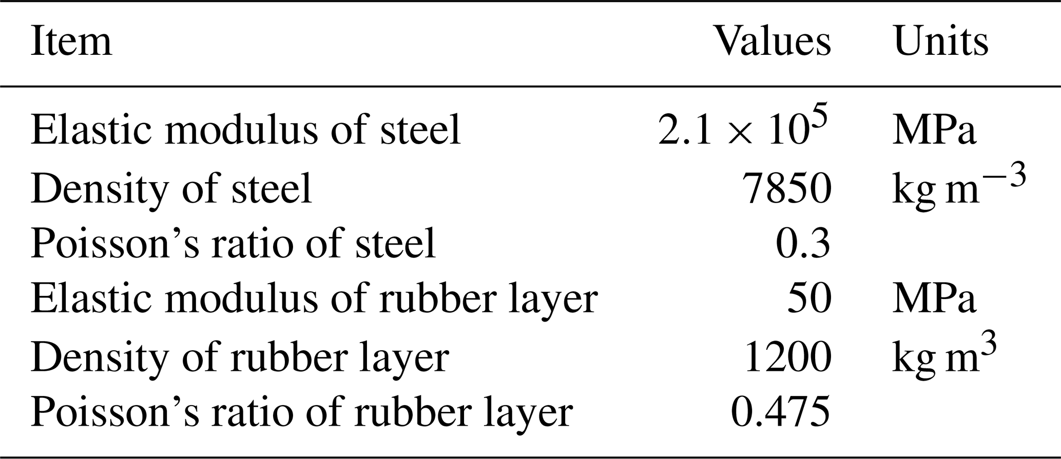
There is a rubber layer in resilient wheels, but standard wheels have no rubber layer. Figure 3 shows the resilient wheelset finite-element model and resilient wheel boundary element model. The finite-element model of the resilient wheelset is shown in Fig. 3a, where the resilient wheelset has a mass of 1310 kg and the standard wheelset has a mass of 1098 kg. The FEM is generated using ABAQUS. The FEM is imported into the multibody dynamics software SIMPACK at a speed of 75 km h−1 to calculate the wheel–rail force in the frequency domain under polygon conditions. The wheel–rail force is then applied to the acoustic model of the wheel shown in Fig. 3b (resilient wheel boundary element model) as a boundary condition. Following this, the SPL of the wheel is calculated in the frequency domain using the acoustic software LMS.VIRTUAL.LAB. The BEM (Liu, 2009; Yang et al., 2025) used to calculate the SPL of the wheel is meshed with tetrahedral cells. The resilient wheel has a mass of 431 kg, and the standard wheel has a mass of 325 kg. The two types of wheels have a diameter of 840 mm. The wheel material parameters used for the simulation in the finite-element and acoustic software are given in Table 1.
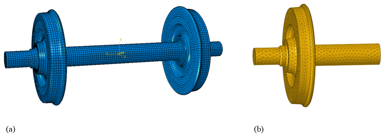
Figure 3Resilient wheelset finite-element model and resilient wheel boundary element model. (a) Finite-element model of the resilient wheelset. (b) Resilient wheel boundary element model.
3.2 Analysis of vertical wheel–rail force
The spectrum of wheel–rail force for the two types of wheels with different polygon orders (0.07 mm polygon amplitude) is shown in Fig. 4. Figure 4a shows the spectrum of wheel–rail force for the standard wheel with different polygon orders, and Fig. 4b shows the spectrum of wheel–rail force for the resilient wheel with different polygon orders. As can be seen, the frequency domain of the wheel–rail vertical force for the two types of wheels is mainly distributed within the 0–80 Hz range. Furthermore, the peak value of the wheel–rail vertical force shifts and is mainly distributed at around 50 Hz. When the polygon order is nine, the vertical wheel–rail force is the largest for both types of wheels, with a peak value of 6.86 kN for the ninth-order polygon of the standard wheel and a peak value of 2.05 kN for the third-order polygon of the standard wheel. The third-order polygon wheel–rail force is 29.88 % of the ninth-order polygon for the standard wheel. The peak vertical wheel–rail force of the resilient wheel is 8.17 kN when the polygon order is nine, whereas the maximum vertical wheel–rail force is only 2.10 kN when the polygon order is three, which is about 25.70 % of the resilient wheel's wheel–rail force at the ninth order. It can be seen that, under the premise of a constant polygon amplitude, the higher the polygon order, the larger the magnitude of the wheel–rail force and the larger the peak frequency of the two types of wheels. This is because the higher the polygon order of the simulated wheel, the more obvious the geometrical change is “sensed” by the contact patch, resulting in stronger interaction. Additionally, the resilient wheel's wheel–rail vertical force is larger than that of the standard wheel because its larger mass corresponds to a greater wheel–rail vertical force.
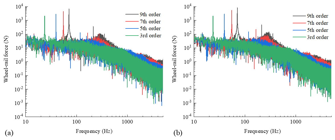
Figure 4Spectrum of wheel–rail force for two types of wheels with different polygon orders (0.07 mm polygon amplitude). (a) Spectrum of wheel–rail force for the standard wheel with different polygon orders. (b) Spectrum of wheel–rail force for the resilient wheel with different polygon orders.
Figure 5 shows the spectrum of wheel–rail force for two types of wheels with different amplitudes of the ninth-order polygon. Figure 5a shows the spectrum of wheel–rail force for the standard wheel with different amplitudes of the ninth-order polygon, and Fig. 5b shows the spectrum of wheel–rail force for the resilient wheel with different amplitudes of the ninth-order polygon. Under the premise of a constant wheel polygon order, it can be seen that the larger the polygon amplitude within the analysed range, the larger the wheel–rail force, with a peak frequency of 71 Hz. When the polygon amplitude is 0.07 mm, the peak vertical wheel–rail force of the standard wheel is 6.86 kN. By comparison, the maximum vertical wheel–rail force for 0.01 mm polygon amplitude is only 2.19 kN, which is approximately 31.7 % of the maximum force for 0.07 mm polygon amplitude. When the resilient wheel has a polygon amplitude of 0.07 mm, the peak vertical wheel–rail force is 8.17 kN; however, when the polygon amplitude is 0.01 mm, the peak vertical wheel–rail force is only 2.31 kN, which is approximately 28.27 % of the 0.07 mm polygon amplitude. This phenomenon can be explained as follows: the larger the simulated polygon amplitude, the more obvious the geometric changes that can be “sensed” by the contact patch. This leads to stronger interactions. For the 0.01 mm polygon amplitude case, the geometric changes are already very smooth for the contact patch, so the corresponding wheel–rail force is smaller.
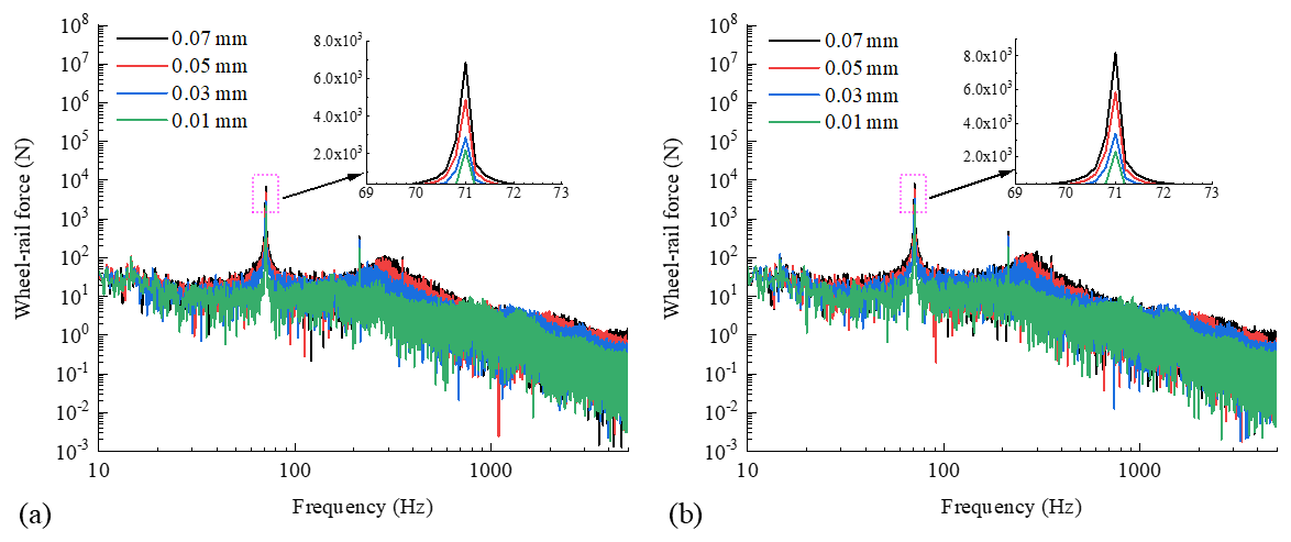
Figure 5Spectrum of wheel–rail force for two types of wheels with different amplitudes of the ninth-order polygon. (a) Spectrum of wheel–rail force for the standard wheel with different amplitudes of the ninth-order polygon. (b) Spectrum of wheel–rail force for the resilient wheel with different amplitudes of the ninth-order polygon.
The spectrum of wheel–rail force for the two types of wheels under curved and straight conditions of the ninth-order polygon with 0.07 mm polygon amplitude is shown in Fig. 6. Figure 6a shows the spectrum of wheel–rail force for the standard wheel under curved and straight conditions of the ninth-order polygon with 0.07 mm polygon amplitude, and Fig. 6b shows the spectrum of wheel–rail force for the resilient wheel under curved and straight conditions of the ninth-order polygon with 0.07 mm polygon amplitude. As can be seen, in most frequency bands, the wheel–rail forces for the two types of wheels under curved conditions are 1 to 1.5 orders of magnitude larger than under straight conditions. The peak frequency for the two types of wheels is 71 Hz. The peak vertical wheel–rail force for the standard wheel under curved conditions is 8.56 kN, and under straight conditions it is 6.86 kN. The straight-condition wheel–rail force is about 80.14 % of that under curved conditions. The peak value of the resilient wheel's vertical wheel–rail force is 9.88 kN under curved conditions, while the peak value of the vertical wheel–rail force is 8.17 kN under straight conditions. Under straight conditions, the wheel–rail force is about 82.69 % of that under curved conditions. The peak wheel–rail force of the resilient wheel is larger than that of the standard wheel under curved and straight conditions due to the resilient wheel's greater mass and stronger interaction with the rail, resulting in larger vertical wheel–rail force.
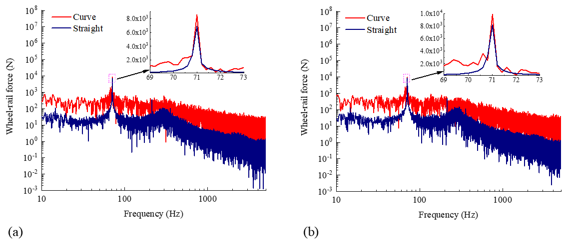
Figure 6Spectrum of wheel–rail force for two types of wheels under curved and straight conditions of the ninth-order polygon with 0.07 mm polygon amplitude. (a) Spectrum of wheel–rail force for the standard wheel under curved and straight conditions of the ninth-order polygon with 0.07 mm polygon amplitude. (b) Spectrum of wheel–rail force for the resilient wheel under curved and straight conditions of the ninth-order polygon with 0.07 mm polygon amplitude.
3.3 Sound radiation characteristics of wheel–rail
The wheel–rail force results in the frequency domain (0.07 mm polygon amplitude) for the two types of wheels with different polygon orders, as shown in Fig. 4, are introduced into the acoustic BEM (shown in Fig. 3b and c) as a force boundary condition. This allows the -octave spectral sound pressure level (0.07 mm polygon amplitude) for the two types of wheels with different polygon orders to be obtained, as shown in Fig. 7. The -octave spectral sound pressure levels for the standard and resilient wheels with different polygon orders are shown in Fig. 7a and b, respectively. In the frequency range of 400–5000 Hz, it is clear that the effect of polygon order on the spectral characteristics of the radiated SPL of the two types of wheels is limited in value. The larger the order, the higher the SPL of the two types of wheels; however, the frequency of the peaks does not change significantly, remaining at 3150 Hz. Additionally, the radiated SPL of the resilient wheel is lower than that of the standard wheel in the 2500–5000 Hz frequency range. The reason for this is that the rubber layer absorbs energy, increasing wheel energy dissipation and reducing wheel vibration, thus reducing the high-frequency SPL.
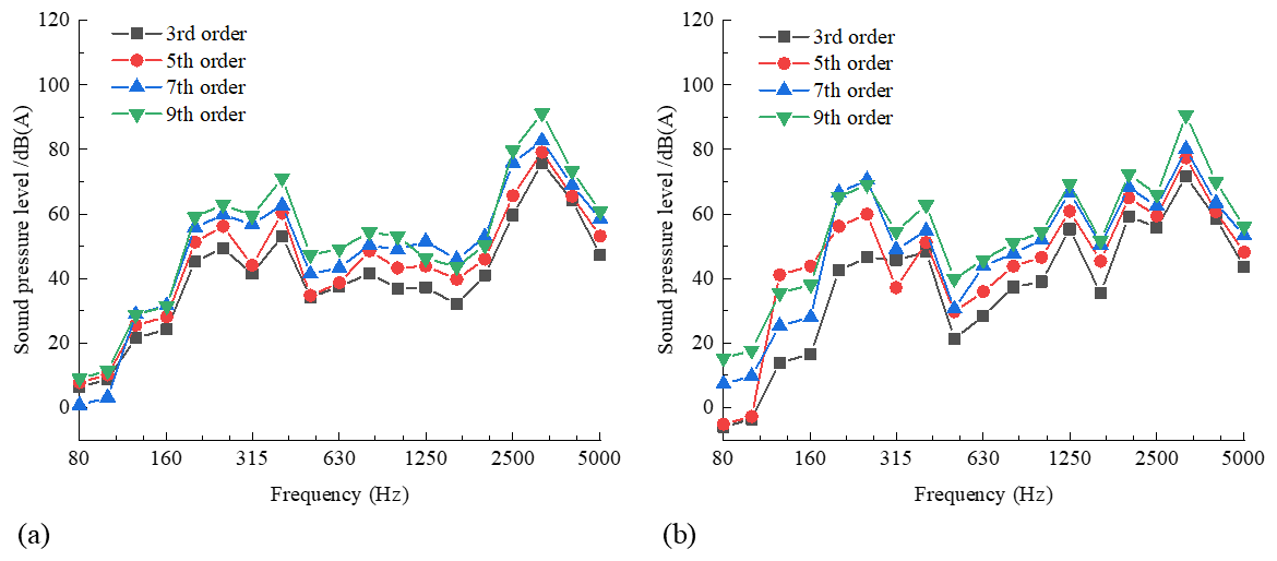
Figure 71/3-Octave spectral sound pressure level (0.07 mm polygon amplitude) for two types of wheels with different polygon orders. (a) -Octave spectral sound pressure level for the standard wheel with different polygon orders. (b) -Octave spectral sound pressure level for the resilient wheel with different polygon orders.
Figure 8 shows the -octave spectral sound pressure level for the two types of wheels with different polygon amplitudes of the ninth-order polygon. Figure 8a shows the -octave spectral sound pressure level for the standard wheel with different polygon amplitudes of the ninth-order polygon, and Fig. 8b shows the -octave spectral sound pressure level for the resilient wheel with different polygon amplitudes of the ninth-order polygon. The standard wheel radiated a low-frequency SPL, with a local peak at 400 Hz frequency, while the resilient wheel showed a peak at 250 Hz. Additionally, there is no significant linear relationship between polygon amplitude and SPL for either wheel in most frequency bands. In the 2500–5000 Hz frequency range, under the same working condition, the SPL radiated by the resilient wheel is generally lower than that of the standard wheel, indicating that the resilient wheel can reduce high-frequency SPL. This is because the rubber layer reduces the wheel's vibration, thus reducing the high-frequency SPL.
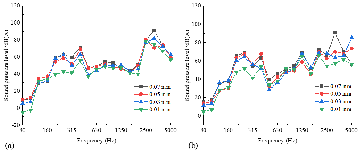
Figure 8-Octave spectral sound pressure level for two types of wheels with different polygon amplitudes of the ninth-order polygon. (a) -Octave spectral sound pressure level for the standard wheel with different polygon amplitudes of the ninth-order polygon. (b) -Octave spectral sound pressure level for the resilient wheel with different polygon amplitudes of the ninth-order polygon.
The -octave spectral sound pressure levels (0.07 mm polygon amplitude) for the two types of wheels under curved and straight conditions with the ninth-order polygon are shown in Fig. 9. The -octave spectral sound pressure levels for the standard and resilient wheels are shown in Fig. 9a and b. Clearly, the curved condition only affects the value of the spectral characteristics of the radiated SPL. In most frequency bands, this value is larger than that under straight conditions. At 5000 Hz, the SPL for the two types of wheels in the value condition is about 38 dB(A) higher than in the straight condition. However, the peak frequencies (3150 Hz) of the two types of wheels do not change significantly. Under the curved and straight conditions, the radiated SPL of the resilient wheel is 2–13 dB(A) lower than that of the standard wheel in the frequency band from 2500–5000 Hz. Additionally, under the curved condition, the radiated SPL of the resilient wheel is 3–10 dB(A) lower than that of the standard wheel in the 2500–5000 Hz frequency band, indicating that the resilient wheel can reduce the SPL under curved conditions at high frequencies. This is because the rubber layer reduces wheel vibration in high-speed and high-frequency conditions, which in turn reduces the SPL.
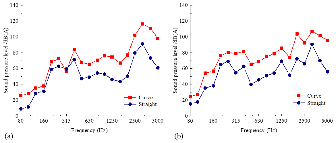
Figure 9-Octave spectral sound pressure level (0.07 mm polygon amplitude) for two types of wheels under curved and straight conditions with the ninth-order polygon. (a) -Octave spectral sound pressure level for the standard wheel under curved and straight conditions with the ninth-order polygon. (b) -Octave spectral sound pressure level for the resilient wheel under curved and straight conditions with the ninth-order polygon.
Analysis of the sound radiation characteristics of the resilient wheel reveals that the viscoelastic properties of the rubber layer produce hysteresis effects in periodic vibration, converting mechanical vibration energy into thermal energy dissipation. This effect is particularly noticeable in high-frequency working conditions (2500–5000 Hz), where there is a significant reduction in vibration and noise. Furthermore, the rubber layer acts as an elastic isolator between the rim and the wheel centre, preventing vibration transmission through impedance mismatch. When the frequency exceeds the critical value, mechanical decoupling occurs in the system, reducing web vibration and sound radiation. The rubber element enhances this vibration isolation effect through pre-compression stresses, making it particularly suitable for high-frequency working conditions (2500–5000 Hz) in metro lines. Additionally, the acoustic impedance of the rubber layer between the metal hub and the air forms a gradient impedance matching layer. This reduces the reflection of sound waves at the interface, increasing the transmittance of sound energy across most frequency bands and reducing SPL by 3–10 dB(A), particularly under curved conditions. At the same time, the porous structure inside the rubber induces sound wave scattering, further depleting high-frequency sound energy. However, the larger wheel–rail force exerted by the resilient wheel induces a transient impact load on the rim, accelerating tread damage. The intensified thermal energy dissipation of the rubber layer accelerates rubber aging, ultimately reducing the wheel's service life.
The vibration damping and noise reduction characteristics of the existing resilient wheel structure have been verified and analysed through numerical calculations. However, the vibration damping and noise reduction characteristics in actual operational lines require further validation, and work in this area remains to be advanced in subsequent phases.
This paper analyses the influence of a typical wheel polygon amplitude and order on wheel–rail force and wheel sound radiation in metro lines. It obtains the wheel–rail contact force corresponding to different polygon amplitudes and orders, as well as curved and straight conditions. It also carries out comparative analysis of the influence of polygon amplitude and order, as well as curved and straight conditions, on wheel sound radiation. The study concludes the following:
-
Increasing the polygon amplitude and order increases the wheel–rail force; the larger the amplitude and the higher the order, the greater the wheel–rail force of both the standard wheel and the resilient wheel. The peak wheel–rail force of the resilient wheel is larger than that of the standard wheel under curved and straight conditions because the resilient wheel's greater mass enhances the wheel–rail interaction at the frequency of 71 Hz, increasing the vertical wheel–rail force.
-
Through comparative analysis of wheel sound radiation with different polygon amplitudes and orders, it was found that, within the 400–5000 Hz frequency range, the higher the polygon order, the greater the SPL of the two types of wheels. In the 2500–5000 Hz frequency domain, the resilient wheel SPL is lower than that of the standard wheel by 2–13 dB(A). Due to damping, energy dissipation, vibration isolation and decoupling effects, and acoustic impedance characteristics, the resilient wheel significantly suppresses noise. Additionally, there is no significant linear relationship between polygon amplitude and the SPL of the two types of wheels in most frequency bands.
-
Under curved conditions, the radiated SPL of the resilient wheel is 3–10 dB(A) lower than that of the standard wheel in the 2500–5000 Hz frequency band. The rubber layer in the resilient wheel increases energy dissipation, reducing the vibration of the web and sound radiation. The porous structure of the rubber also scatters sound wave, further consuming high-frequency acoustic energy. This ultimately reduces the SPL at high speeds and frequencies.
The code and data generated and supporting the findings of this article are obtainable from the corresponding author upon reasonable request.
Conceptualisation, Y.C.; methodology, Y.C. and J.T.; formal analysis, Y.C. and J.T. All authors read and agreed to the published version of the paper.
The contact author has declared that none of the authors has any competing interests.
Publisher's note: Copernicus Publications remains neutral with regard to jurisdictional claims made in the text, published maps, institutional affiliations, or any other geographical representation in this paper. The authors bear the ultimate responsibility for providing appropriate place names. Views expressed in the text are those of the authors and do not necessarily reflect the views of the publisher.
This work was supported by Natural Science Basic Research Program of Shaanxi Province (grant no. 2025JC-YBMS-085), and President's Fund of Xi'an Technological University (grant no. XGPY200213), and education and teaching reform project of Xi'an Technological University (grant no. 23JGY002).
This paper was edited by Liangliang Cheng and reviewed by Nicolò Gori and two anonymous referees.
Cheng, G., He, Y. P., Han, J., Sheng, X. Z., and Thompson, D.: An investigation into the effects of modelling assumptions on sound power radiated from a high-speed train wheelset, Journal of Sound and Vibration, 495, 115910, https://doi.org/10.1016/j.jsv.2020.115910, 2021.
Desmet, W., Sas, P., and Vandepitte, D.: Numerical acoustics-theoretical manual, LMS International, 1998.
Han, J.: Research on vibration sound radiation and directivity of train wheels, Master thesis, Southwest Jiaotong University, China, 76 pp., 2012.
He, Y. P., Wang, X. H., Han, J., Xiao, X. B., and Sheng, X. Z.: Study on the influence of resilient wheels on vibration and acoustic radiation characteristics of suburban railway concrete box girder bridges, Applied Acoustics, 187, 108529, https://doi.org/10.1016/j.apacoust.2021.108529, 2022.
He, Y. P., Zhou, Q., Xu, F., Sheng, X. Z., He, Y. L., and Han, J.: An investigation into the effect of rubber design parameters of a resilient wheel on wheel-rail noise, Applied Acoustics, 205, 109259, https://doi.org/10.1016/j.apacoust.2023.109259, 2023.
Liu, Y. J.: Fast Multipole Boundary Element Method-Theory and Applications in Engineering, Cambridge University Press, 2009.
Nielsen, J.: Out-of-round railway wheels, in: Wheel-rail interface handbook, Cambridge: Woodhead Publishing, pp. 245–279, https://doi.org/10.1533/9781845696788.1.245, 2009.
Remington, P. J.: Wheel/rail noise–Part I: Characterization of the wheel/rail dynamic system, Journal of Sound and Vibration, 46, 359–379, https://doi.org/10.1016/0022-460X(76)90861-0, 1976a.
Remington, P. J.: Wheel/rail noise, Part IV: Rolling noise, J. Sound Vib, 46, 419–436, https://doi.org/10.1016/0022-460X(76)90864-6, 1976b.
Song, Z. K., Yue, R., and Hu, X.: The influence of wheel polygon on vehicle vibration and wheel-rail force, J. Beijing Jiaotong Univ, 41, 88–93, https://doi.org/10.11860/j.issn.1673-0291.2017.06.014, 2017.
Song, Z. K., Ren, H. X., Liu, W., Li, Q., and Hu, X. Y.: Study on the influencing factors in the development process of high-speed train wheel polygon, Adv Mech Eng, 14.8, https://doi.org/10.1177/16878132221115015, 2022.
Song, Z. K., Wang, F., Hu, X. Y., Cheng, D., and Li, Q.: Influences of wheel polygon amplitude on wheel-rail vibration and sound radiation, Journal of Low Frequency Noise, Vibration and Active Control, 42.2, 477–495, https://doi.org/10.1177/14613484231152850, 2023.
Tao, G., Wen, Z., Jin, X., and Yang, X.: Polygonisation of railway wheels: a critical review, Railw. Eng. Sci, 28, 317–345, https://doi.org/10.1007/s40534-020-00222-x , 2020.
Thompson, D. J.: Wheel-rail noise generation, Part I: Introduction and interaction model, J. Sound Vib, 161, 387–400, https://doi.org/10.1006/jsvi.1993.1082, 1993.
Thompson, D. J.: Railway noise and vibration: mechanism, modeling and means of control, Amsterdam: Elsevier, 2008.
Thompson, D. J., Hemsworth, B., and Vincent, N.: Experimental validation of the TWINS prediction program for rolling noise, Part I: Description of the model and method, J. Sound Vib, 193, 123–135, https://doi.org/10.1006/jsvi.1996.0252, 1996a.
Thompson, D. J., Fodiman, P., and Mahé, H.: Experimental validation of the TWINS prediction program for rolling noise, Part II: Results, J. Sound Vib, 193, 137–147, https://doi.org/10.1006/jsvi.1996.0253, 1996b.
Wang, C.: Train wheel vibration sound radiation prediction and development of wheel vibration and noise reduction device, Master thesis, Southwest Jiaotong University, China, 82 pp., 2012.
Wang, H. B., Li, G. F., Wang, Z. G., and Ding, W. C.: Analysis of the Influence of Wheel Polygons on Vehicle Dynamic Performance, Railway Standard Design, 64, 165–171, https://doi.org/10.13238/j.issn.1004-2954.201906030011, 2020a.
Wang, B., Xie, S., Jiang, C., Song, Q., Sun, S., and Wang, X.: An investigation into the fatigue failure of metro vehicle bogie frame, Engineering Failure Analysis, 118, 104922, https://doi.org/10.1016/j.engfailanal.2020.104922, 2020b.
Wei, Z., Sun, X., Yang, F., Ke, Z., Lu, T., Zhang, P., and Shen, C.: Carriage interior noise-based inspection for rail corrugation on high-speed railway track, Applied Acoustics, 196, 108881, https://doi.org/10.1016/j.apacoust.2022.108881, 2022.
Wu, H., Wu, P., Li, F., Shi, H., and Xu, K.: Fatigue analysis of the gearbox housing in high-speed trains under wheel polygonization using a multibody dynamics algorithm, Eng. Fail. Anal, 100, 351–364, https://doi.org/10.1016/j.engfailanal.2019.02.058, 2019.
Wu, X., Chi, M., and Gao, H.: Damage tolerances of a railway axle in the presence of wheel polygonalizations. Eng. Fail. Anal, 66, 44–59, https://doi.org/10.1016/j.engfailanal.2016.04.009, 2016.
Wu, Y., Han, J., and Jia, L.: The influence of high-speed train wheel polygon wear on wheel-rail force and bogie vibration behavior, Chin J Mech Eng, 54, 37–46, https://doi.org/10.3901/jme.2018.04.037, 2018.
Wu, T. X. and Thompson, D. J.: On the impact noise generation due to a wheel passing over rail joints, Journal of Sound and Vibration, 267, 485–496, https://doi.org/10.1016/S0022-460X(03)00709-0, 2003.
Yang, Y., Ling, L., Wang, C., Liu, Z., Wang, K., and Zhai, W.: Wheel/rail dynamic interaction induced by polygonal wear of locomotive wheels, Vehicle system dynamics, 60, 211–235, https://doi.org/10.1080/00423114.2020.1807572, 2022.
Yang, Y., Wei, X., and Liu, Y. J.: A novel multiscale crack propagation modeling approach based on adaptive coupling of peridynamics and boundary element method, Engineering Fracture Mechanics, 325, 111291, https://doi.org/10.1016/j.engfracmech.2025.111291, 2025.
Zhou, X., Liu, Z., Zhong, S., An, T., Sheng, X., and Thompson, D.: In-situ assessment of the sound and vibration reduction performance of a new type of resilient wheel installed on a metro train, Vehicle System Dynamics, 62, 2936–295, https://doi.org/10.1080/00423114.2024.2305299, 2024.