the Creative Commons Attribution 4.0 License.
the Creative Commons Attribution 4.0 License.
 | 13 Apr 2026
Improved adaptive fuzzy sliding-mode control for seat suspension based on magnetorheological fluid (MRF) damper
Yabing Jing
Yongqin Liang
Xiuxiu Sun
This paper introduces an improved adaptive fuzzy sliding-mode control approach for semi-active seat suspension utilizing magnetorheological fluid (MRF) dampers. Firstly, the damping characteristic of the MRF damper was tested, and the dynamics model of MRF damper was established. Secondly, the 5-degree-of-freedom “human-seat” suspension system model was built and adaptively simplified, and a suitable adaptive control law was designed to estimate the perturbations generated during the simplification process of the human-seat model online. Based on the simplified model, a fuzzy algorithm was adopted to optimize the approach rate parameters in the sliding-mode control so as to improve the robustness of the system while guaranteeing the approach rate, and hyperbolic tangent function was employed to replace the sign function in the switching term to make the system more continuous during the switching process, which effectively reduces the “chatter” problem in the sliding-mode control. Thirdly, the dynamics model of the MRF damper is added into the sliding-mode control model to ensure the effectiveness of the MRF damper output control force. Finally, the effectiveness of the improved adaptive fuzzy sliding-mode control method was confirmed through simulation, demonstrating its capability to significantly reduce seat acceleration and suspension dynamic deflection under different working conditions compared with passive damping, skyhook control, and sliding-mode control.
- Article
(5740 KB) - Full-text XML
- BibTeX
- EndNote


Heavy commercial vehicles, tractors, and construction machinery have high inherent suspension frequencies due to their own performance needs. When the vehicle is driven in a harsh working environment, the unevenness of the road surface, potholes, and other factors will cause frequent low-frequency vibration problems in the cab. If the driver is exposed to this working environment for a long time, it will seriously affect their work efficiency or, worse, cause serious harm to their body (Maciejewski, 2012). To attenuate the vibration transmitted from the vehicle to the driver's body and to improve the vehicle driver's comfort, research on seat damping is necessary, and so conducting seat damping research for commercial vehicles and off-road vehicles is of great scientific significance and application value (Yin et al., 2021). The main research elements of vehicle seat damping include seat structure optimization, improved seat cushion design, and increased seat damping suspension. Among them, the optimized seat structure and cushion design cannot effectively attenuate the low-frequency and large-amplitude vibration excitation that is most harmful to drivers. Therefore, the design of seat suspension damping has become a hot topic of current research (Zhao et al., 2021).
The current seat suspension mainly has three types: passive, active, and semi-active (Wang et al., 2022). The passive seat suspension has a simple structure and high reliability, but, due to its stiffness and damping coefficient, the vibration attenuation ability is limited and cannot effectively attenuate low-frequency vibration; the active suspension has a good damping effect and can effectively attenuate low-frequency vibration, but its use is also affected by its high cost and low reliability (Rosli et al., 2021). Semi-active suspension has good application prospects in the field of seat damping because it has the advantages of simple structure, high reliability, and a similar damping effect in relation to active suspension (Sun et al., 2018). Shen et al. (2026) proposed a semi-active inerter–spring–damper (ISD) system, with a solenoid-valve-regulated fluid inerter as its core component. This design leverages the frequency-dependent negative stiffness characteristic of the inerter to improve the dynamic performance of the suspension system.
Semi-active seat suspensions can be divided into three types: damping adjustable, stiffness adjustable, and stiffness–damping adjustable at the same time. Variable damping dampers are mainly electrical, magnetorheological fluid (MRF) dampers, mechanically adjustable damping-adjustable dampers, motor-controlled damping-adjustable dampers, and other types, of which magnetorheological liquid dampers have been widely used in construction, bridges, and automotive suspensions due to their low energy consumption, simple structure, large adjustable damping-force range, and rapid response (Sun et al., 2015).
Bai et al. (2016) developed a semi-active seat suspension system based on a rotating MRF damper, and the torque of the MRF damper can be increased linearly from 1.02 to 13.53 N m within a certain current range, and this seat system can achieve a better damping effect when vibrating at high speed or under impact. Sun et al. (2016) proposed a seat suspension with a rotary MRF damper for heavy-duty vehicles and achieved a good vibration reduction effect. Hu et al. (2020) applied magnetorheological liquid dampers to the seat suspension of an armored vehicle and designed an optimal semi-active control algorithm, which also achieved good control results. Deng conducted an investigation on a seat suspension featuring compact variable stiffness and damping rotary magnetorheological dampers (Deng et al., 2022). Yu et al. (2020) developed an enhanced magnetorheological rotary damper for seat suspension, which demonstrated significant efficiency in reducing vibrations.
In semi-active suspension, the study of control algorithms as a key issue of semi-active control can effectively enhance the vibration-damping capability of semi-active suspension. The control algorithms mainly include PID (proportional integral derivative) control (Yang et al., 2023a), adaptive control (Song et al., 2005), fuzzy control (Hu et al., 2017), sliding-mode control (Yang et al., 2023b), H control (Du et al., 2019), LCPP (low-complexity prescribed performance) control (Wang et al., 2026), etc. Sliding-mode control stands out for its robustness among these control methods, but, due to the influence of measurement errors, time lags, and other factors, this method can cause chattering problems in the control process, which seriously affects the effect of sliding-mode control. In this paper, the hyperbolic tangent function replaces the sign function in the switching term of the convergence rate so that the boundary layer of the system can shrink continuously with the state trajectory, thus effectively suppressing the chatter problem of sliding-mode control.
In addition, since the MRF damper is used in this study to realize the sliding-mode control, the mechanical properties of the MRF damper need to be considered in the study of the control algorithm. Meanwhile, the human body attitude is involved in the vehicle seat vibration control. Existing studies usually simplify the human-seat system model directly into a single-degree-of-freedom vibration model for control, but this treatment ignores the influence of the human body's attitude changes on the controller during vehicle driving.
In light of the above analysis, this paper presents an improved adaptive fuzzy sliding-mode control method for semi-active seat suspension. The initial step involves establishing the dynamics model of the MRF damper and subsequently confirming the model's accuracy. Then, a 5-degree-of-freedom human seat model has been developed and simplified for seat vibration control, and a suitable adaptive control law is designed to estimate the perturbations and external disturbances generated during the simplification process of the human seat model in real time online. Then, a sliding-mode control method based on an exponential convergence rate is designed to calculate the desired damping force of the semi-active seat suspension. In order to solve the problem of chatter in the sliding-mode control, fuzzy control is used to optimize the convergence law, and, in the design process of the convergence law, a hyperbolic tangent function is chosen to replace the sign function in the convergence law switching term so as to reduce the chatter of the system.
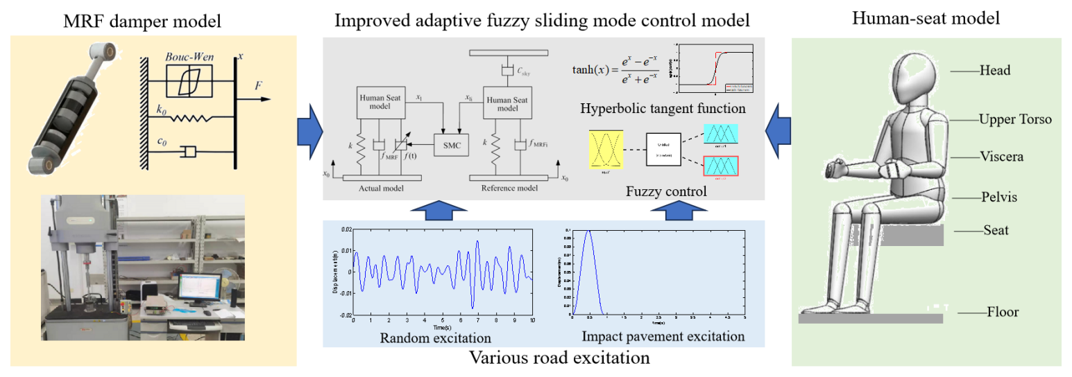
Building upon these considerations, the mechanical properties of the MRF damper are integrated into the sliding-mode control method by incorporating the damper's dynamic model. The reference model for the sliding-mode control is based on the ideal skyhook control method, which takes into account the dynamics of the MRF damper. The damping-force outputs the control force through the MRF damper inverse model. Finally, the control algorithm's performance is evaluated using simulation analysis across various road conditions. Additionally, a comparative analysis with other control methods is conducted to confirm the efficacy of the method outlined in this paper. The main research content of the paper is shown in Fig. 1.
MRF damper is a new type of damper that employs magnetorheological fluid as its working medium and achieves precise control of the damping force through current transformation. This kind of damper has the advantages of an extensive variable range of damping force, rapid response, easy-to-realize real-time control, wide operating temperature range, and high stability (Morales et al., 2018). Establishing an accurate dynamic model is necessary to achieve precise control of MRF damper.
2.1 Dynamic-characteristic test of MRF damper
When constructing the dynamic model of the MRF damper, it is imperative to conduct tests to assess its dynamic characteristics. The Instron E10000 electronic dynamic and static testing machine was used in this experiment. The MRF damper used in this study has a stroke of 35 mm, a tensile length of 230 mm, and a diameter of 40 mm. The sinusoidal signal with displacement amplitudes of 5 and 10 mm and frequencies of 1, 2, and 3 Hz were applied to the damper. The control currents of the experiment were 0, 1, 2, 3, 4 and 5 A. The experimental process is shown in Fig. 2. This paper selects the experimental results of 10 mm, 2 Hz working conditions to analyze, as shown in Fig. 3.
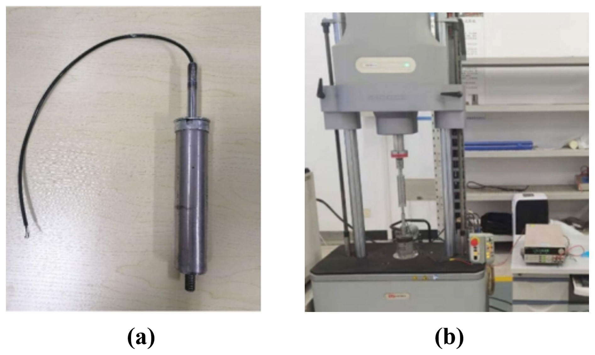
Figure 2Mechanical characteristics test of MRF damper. (a) The MRF damper used in the research, (b) Dynamic-characteristic test.
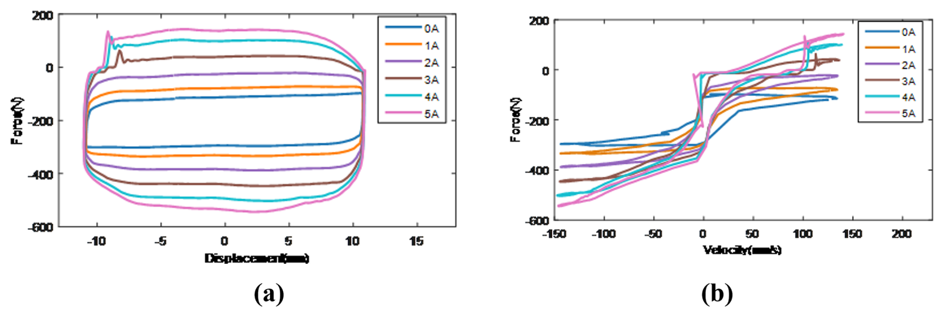
Figure 3Damping-characteristic diagram of the MRF damper. (a) The 10 mm–2 Hz displacement force characteristic and (b) the 10 mm–2 Hz speed force characteristic.
As evident from the experimental findings depicted in Fig. 3, the damping-force and displacement curves of the MRF damper are approximately elliptical and relatively full, indicating that the damper has good energy consumption and vibration attenuation performance during operation. The damping force of the MRF damper experiences a significant increase as the input current rises, indicating that the damper has good current control performance.
2.2 The forward dynamic model of the MRF Damper
Common forward dynamic models of MRF dampers include the Bingham model (Stanway et al., 1987), the polynomial model (Choi et al., 2001), the Bouc–Wen model (Bouc, 1976), and the hyperbolic tangent model (Kwok et al., 2006). Among them, the Bouc–Wen model finds widespread use due to its ability to represent the nonlinear characteristics of MRF dampers more effectively. Therefore, this paper employs the Bouc–Wen model to represent the dynamics of MRF damper. The damping-force expression of the Bouc–Wen model is as follows (Wen, 1976):
In this context, the variables are defined as follows: F represents the damping force of the MRF damper, c0 is the viscosity coefficient of the magnetorheological fluid after yielding, x signifies the relative displacement between the two ends of the damper, is the relative velocity of the two ends of the damper, x0 is the relative equilibrium position offset displacement, z is the hysteresis variable, n is the curve-rounding coefficient, γ is the adjustment coefficient of the hysteresis loop width, β is the adjustment coefficient of the hysteresis loop height, α is the adjustment coefficient of the proportion of the total damping force, and A is the scaling factor related to the maximum damping force.
In this research, the parameter identification of the Bouc–Wen model is conducted using the Simulink parameter estimation module in MATLAB. The initial step involves constructing the Bouc–Wen model in Simulink. After completing the modeling, the test data are imported.
After completing the modeling, we then import the test data. The input value was the displacement of the damper piston, and the output was damping force. Then we selected the parameters to be identified. Firstly, the damping-characteristic curves for the 10 mm, 2 Hz working condition were integrated into the Simulink model. Subsequently, the Bouc–Wen model's eight parameters were derived through the initial identification process. Various parameters exert distinct influences on the model. Further comparison shows that the fluctuations of the two parameters α and c0 are significant under different currents, and so the remaining parameters are held constant during the subsequent parameter identification process. The values of the two parameters α and c0 under different currents are identified separately, and, finally, the relationship curves between these two parameters and the current are fitted. The parameter identification results are shown in Table 1 (I is the current in Table 1), and a comparison of the model fitting results with the experimental results is shown in Fig. 4.
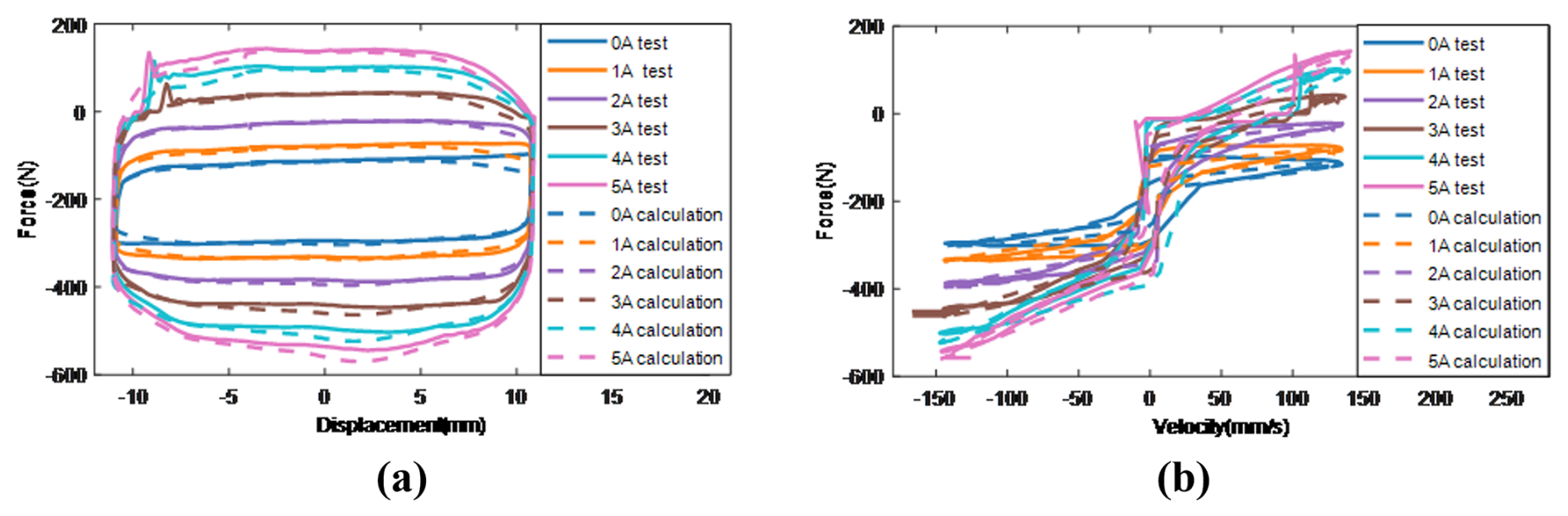
Figure 4Comparison of test and simulation models' (a) 10 mm, 2 Hz displacement–force characteristic and (b) 10 mm, 2 Hz speed–force characteristic.
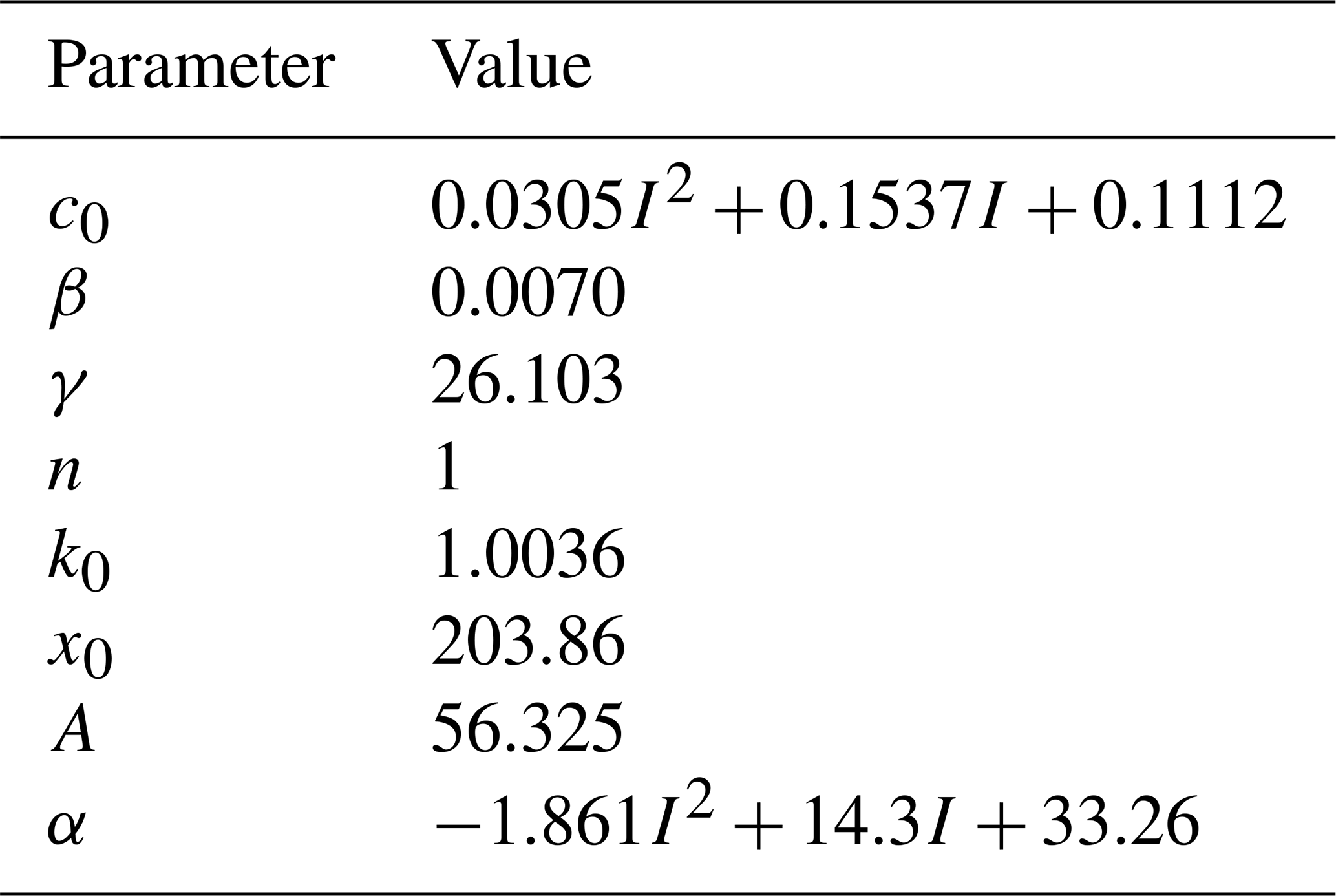
Figure 4 displays the force–displacement and force–velocity characteristic curves of the MRF damper. The solid and dashed lines indicate the experimental measurements and the calculated values of the Bouc–Wen simulation model under the currents of 0, 1, 2, 3, 4, and 5 A. The figures show that the damping force calculated by the MRF damper dynamic model established in this paper is consistent with the actual damping force obtained from the experimental tests, which can meet the requirements of semi-active control.
To further verify the universality of the identified model under different working conditions, the test data obtained under other working conditions should be input into the model for validation. The comparison results are shown in Fig. 5.
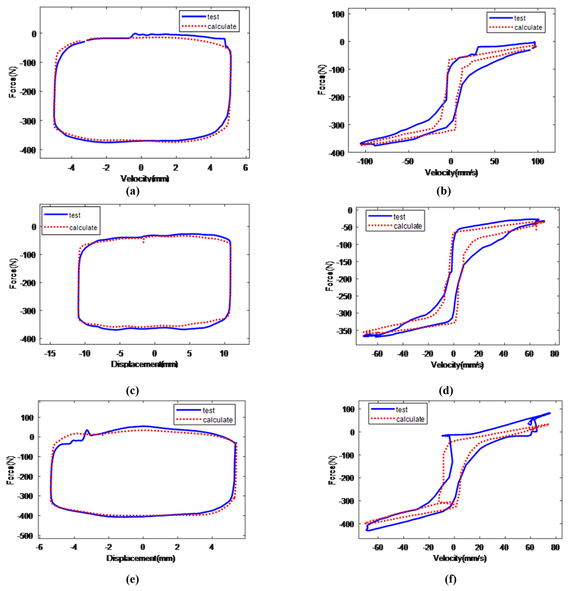
Figure 5The fitting model compared with the experimental model (a) 5 mm, 3 Hz, 2 A indicator diagram; (b) 5 mm, 3 Hz, 2 A speed characteristic diagram; (c) 10 mm, 1 Hz, 2 A indicator diagram; (d) 10 mm, 1 Hz, 2 A speed characteristic diagram; (e) 5 mm, 2 Hz, 4 A indicator diagram; and (f) 5 mm, 2 Hz, 4 A speed characteristic diagram.
As can be seen from Fig. 5, the identified Bouc–Wen model can accurately reflect the displacement–damping-force characteristics and velocity–damping-force characteristics of the magnetorheological fluid damper and exhibits good universality under different working conditions
2.3 The inverse dynamic model of the MRF Damper
In the context of semi-active seat suspension control, the control force is determined through a control method but then needs to be transmitted via the magnetorheological fluid (MRF) damper. This entails adjusting the current of the MRF damper to achieve the desired control force, which requires the establishment of an inverse dynamics model for the MRF damper. The MRF damper's forward dynamics model is complex, presenting significant nonlinearity in the relationship between output damping force, input control current, relative piston displacement, and velocity. This complexity makes it challenging to derive the control current directly from the desired control force using a direct mathematical method (Gao et al., 2023). To address this, our approach employs a BP neural network to establish the inverse model for the MRF damper.
Training data samples are generated to ensure comprehensive coverage of the MRF damper's operational range, with consideration of the structural parameters used in this study. These samples involve random excitation signals with displacements of less than 10 mm as input training data and their derivatives as velocity input training data. For control input current, random white-noise signals in the range of 0–5 A serve as training samples. These training samples are then fed into the Bouc–Wen dynamic model of the MRF damper, producing the corresponding output damping force as training data.
Once the BP neural network inverse model for the MRF damper has been successfully trained, a selected dataset is utilized to test the neural network's ability to predict the control current. Then the error between predicted current and actual current is calculated. The prediction results and error analysis are presented in Fig. 6.
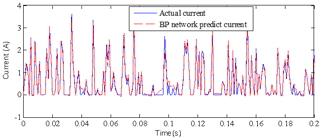
It can be seen from Fig. 6 that the current values predicted by the BP neural network model established in this paper are in good agreement with the actual current values. A further analysis of the current prediction error shows that the maximum current prediction error is 0.71 A. The root mean square (rms) value of the prediction error for the BP neural network is remarkably low, measuring at just 0.168 A. This level of accuracy fulfills the control requirements of the MRF damper. Following the establishment of both the dynamic and inverse dynamic model of the MRF damper, the calculation of the MRF damper's control current can be carried out based on the expected control force derived from the semi-active control algorithm.
3.1 The establishment of the human-seat suspension model
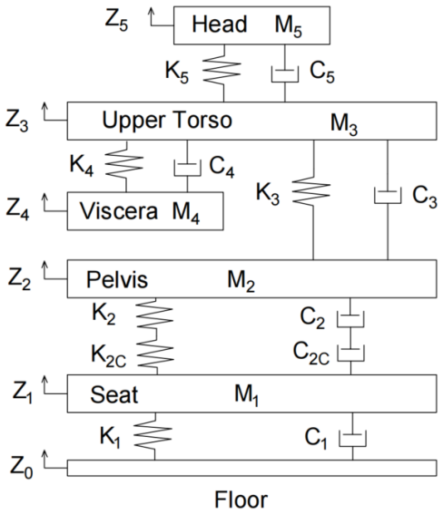
When establishing the human-seat suspension model, this paper adopts the 5-degree-of-freedom human-seat model (Wang et al., 2018) for semi-active control research, as shown in Fig. 7. In the figure, M1–M5, respectively represent the mass of the seat itself, the mass of the human pelvis, the mass of the human viscera, the mass of the upper torso, and the mass of the head. k1–k5, respectively, represent the stiffness of the seat suspension, the stiffness of the human pelvis, the stiffness of the human viscera, the stiffness of the upper torso, and the stiffness of the head; fMRF is the damping force of the MRF damper when no current is added to it; c2–c5 are the damping coefficients of the human pelvis, the damping of the upper torso, the damping of the human viscera, and the damping of the head, respectively; k2c and c2c are the stiffness and damping coefficient of the seat cushion, respectively, x0–x5 represent the displacement of the vehicle floor, seat cushion, pelvis, upper torso, viscera, and head. In addition, the MRF damper can directly generate control force after current is applied, and the generated control force is represented by f(t). The system dynamic equation is shown in Eq. (2).
3.2 Model simplification
To precisely control the multi-degree-of-freedom human-seat suspension system, it is necessary to determine each part's stiffness and damping coefficients. Due to the nonlinear structure of the human body, its stiffness and damping coefficients will constantly change with different postures during practical operation, making it difficult to measure accurately. The design of semi-active control algorithms based on multiple-degree-of-freedom systems is complex and difficult to apply in practical engineering. By simplifying the human-seat suspension system model, we can simplify the controller design and make it easier to apply in practical engineering. However, during model simplification and actual seat operation, a series of disturbances may occur, and so it is necessary to estimate these interferences to improve the accuracy of control. In this paper, the human body model was simplified for the control strategy, where the mass parameters from m1 to m5 were considered as a whole. Herein, m1 refers to the mass of the seat cushion, and the sum of m2 to m5 represents the mass of the human body supported by the seat in the sitting posture. In this paper, the values of m1 to m5 are taken from the model parameters in the reference (Wang et al., 2018), where m1 = 22 kg, m2 = 27 kg, m3 = 20 kg, m4 = 9 kg, m5 = 5.5 kg, and the sum of m2 to m5 is 61.5 kg. The seat stiffness k1 is set to 15 000 N m−1. We simplify the 5-degree-of-freedom human-seat suspension system model established in this paper as shown below.
In the above equations, f(s) represents the disturbance generated during the simplification process of the model, and Δf(t) represents the disturbance generated externally by the seat during actual operation. We select , , and then
In the above equations,
To achieve the optimal vibration reduction effect, the semi-active seat suspension system can adjust the damping coefficient in the suspension system in real time based on the vibration of the vehicle floor as measured by sensors. This adjustment is mainly realized through a semi-active control strategy, and so designing a suitable semi-active controller is crucial in the research of semi-active seat suspension. When the vehicle is driven in a harsh environment, the semi-active seat suspension control algorithm needs to be robust due to the complexity of the loads and the uncertainties and nonlinearities that are difficult in relation to model in the human-seat suspension system. Therefore, this paper designed an improved adaptive fuzzy sliding-mode method for semi-active seat suspension.
4.1 Reference model design
Conventional sliding-mode control is difficult to apply in practice due to the high cost of the required state variables; to overcome the above problems, most of the current sliding-mode controllers are designed by using the model reference method. The principle is that an ideal model is selected as the reference model, and a suitable control force is output to control the actual controlled system with a suitable control force so that it can achieve the same control effect as the ideal control system. Since this paper adopts an MRF damper to realize the semi-active control of seat suspension, it needs the output of semi-active control force through variable damping force, and so, combining with the working characteristics of MRF damper, this paper selects the ideal skyhook control as the reference model and added the dynamics model of MRF damper (established in the second part of the paper) into the reference model, as shown in Fig. 8. Since the controller designed in this paper is implemented based on an MRF damper, the dynamic model of the MRF damper is incorporated into the control system to ensure that the control force calculated by the controller can be rapidly output by the MRF damper. Specifically, the dynamic model of the MRF damper is included in both the actual model and the reference model for sliding-mode control. The MRF damper's output damping force consists of two components: the fixed damping force and the variable damping force. The fixed damping force arises when the input current is zero and depends on the damper piston's velocity. This remains unalterable. The variable damping force, on the other hand, is modifiable through adjustments to the input current. In the reference model, the fixed damping force is denoted as fMRFi, and, in the actual model, the fix damping force is denoted as fMRF.
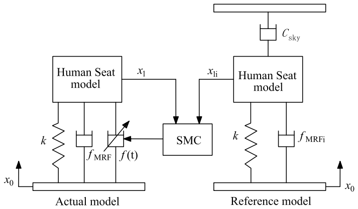
The motion state error between the actual system and the reference model is chosen as the input into the sliding-mode controller. This controller acts to reduce the dynamic error between the actual model and the reference model and to keep it in the sliding mode. Consequently, the motion state of the actual model can effectively track the reference model, which particularly enhances the frequency response of the seat suspension in the low-frequency range.
The kinetic equation of the reference model is as follows:
where fMRFi and fMRF are the fixed damping force of the reference model and actual model, respectively; x0 is the input vibration displacement of the cab floor; x1i and x1 are the seat platform displacements of the reference and actual models, respectively; k is the seat suspension stiffness of the reference and actual models; Csky is the skyhook damping coefficient; and f(t) is the skyhook damping force of the reference model, expressed as follows:
4.2 Sliding-mode controller design
The fundamental concept behind the sliding-mode controller developed in this paper is to enable the motion state of the actual model to track the reference model's motion state as closely as possible. Therefore, the error vector is defined as the combination of the velocity error, the displacement error, and the integral of the displacement error between the actual model and the reference model, as shown in Eq. (13) (Liu et al., 2008).
Differentiating Eq. (13), the kinetic equations of the system are obtained as follows:
In this equation,
Then, sliding-mode control is applied to the above error dynamic system, and the sliding-mode surface is designed as follows:
where c1 and c2 are parameters to be determined and should satisfy the polynomial as Hurwitz polynomials; to satisfy the above condition, take (p+λ)2 = 0 = 0 and λ>0, where c1=λ2, and c2 = 2λ.
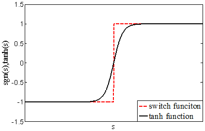
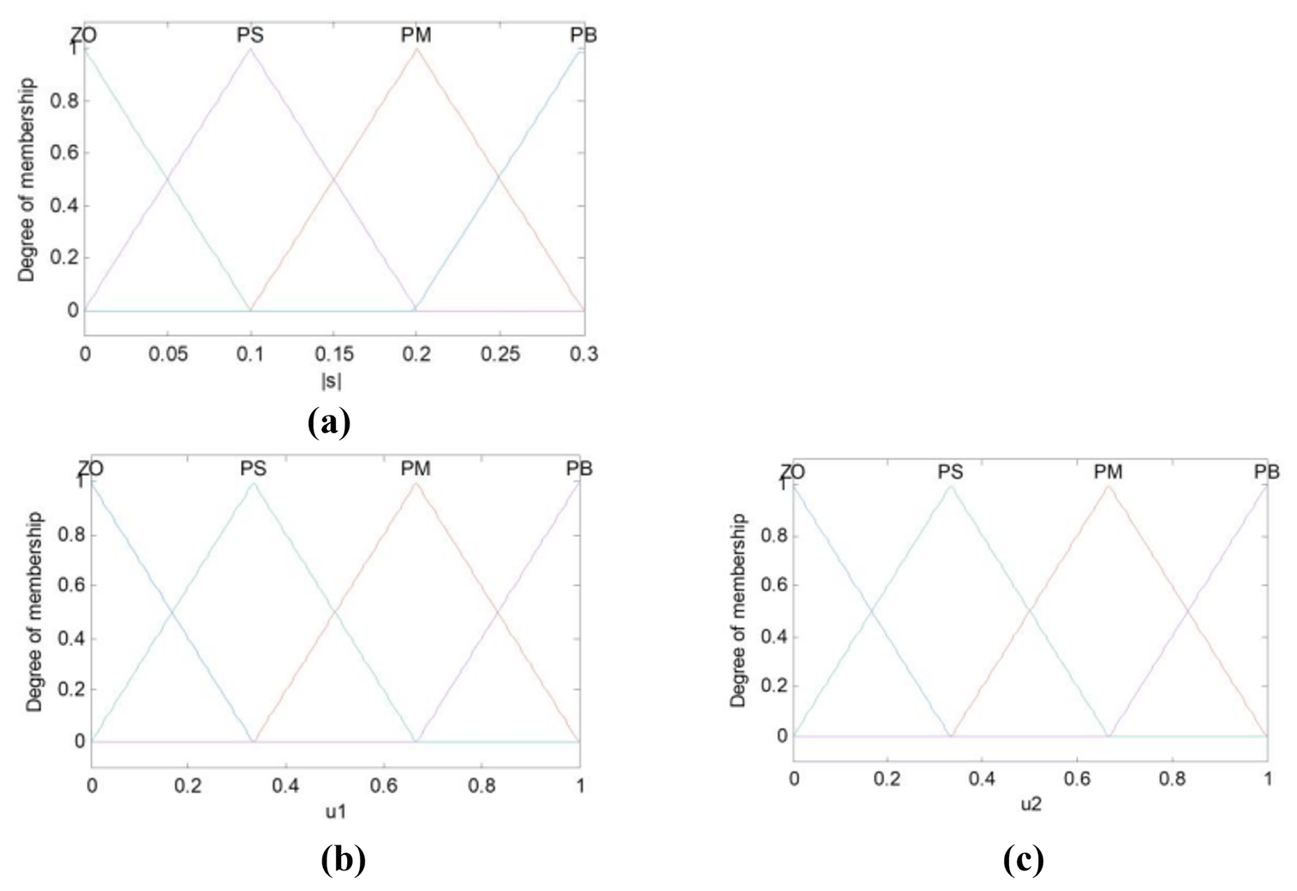
Figure 10Membership function of fuzzy control (a) input variable , (b) output variable α1, and (c) output variable α2.
A convergence law is used to design the sliding-mode surface:
The index convergence law is designed as follows:
In the equation, is the exponential convergence term, which can ensure that, when s is large, the system state can approach the switching surface s at a relatively high speed, with k > 0; . The constant velocity approach term ensures that the moving point can reach the switching surface within a finite time; ε > 0 is a symbolic function that can be represented as follows:
From Eqs. (17) and (18), the following can be obtained:
Bringing the matrices G(t), A(t), B(t), and E(t) and the vector c into Eq. (20), the result is shown as follows:
Define the Lyapunov function as , taking the derivative of V1, the result is as follows:
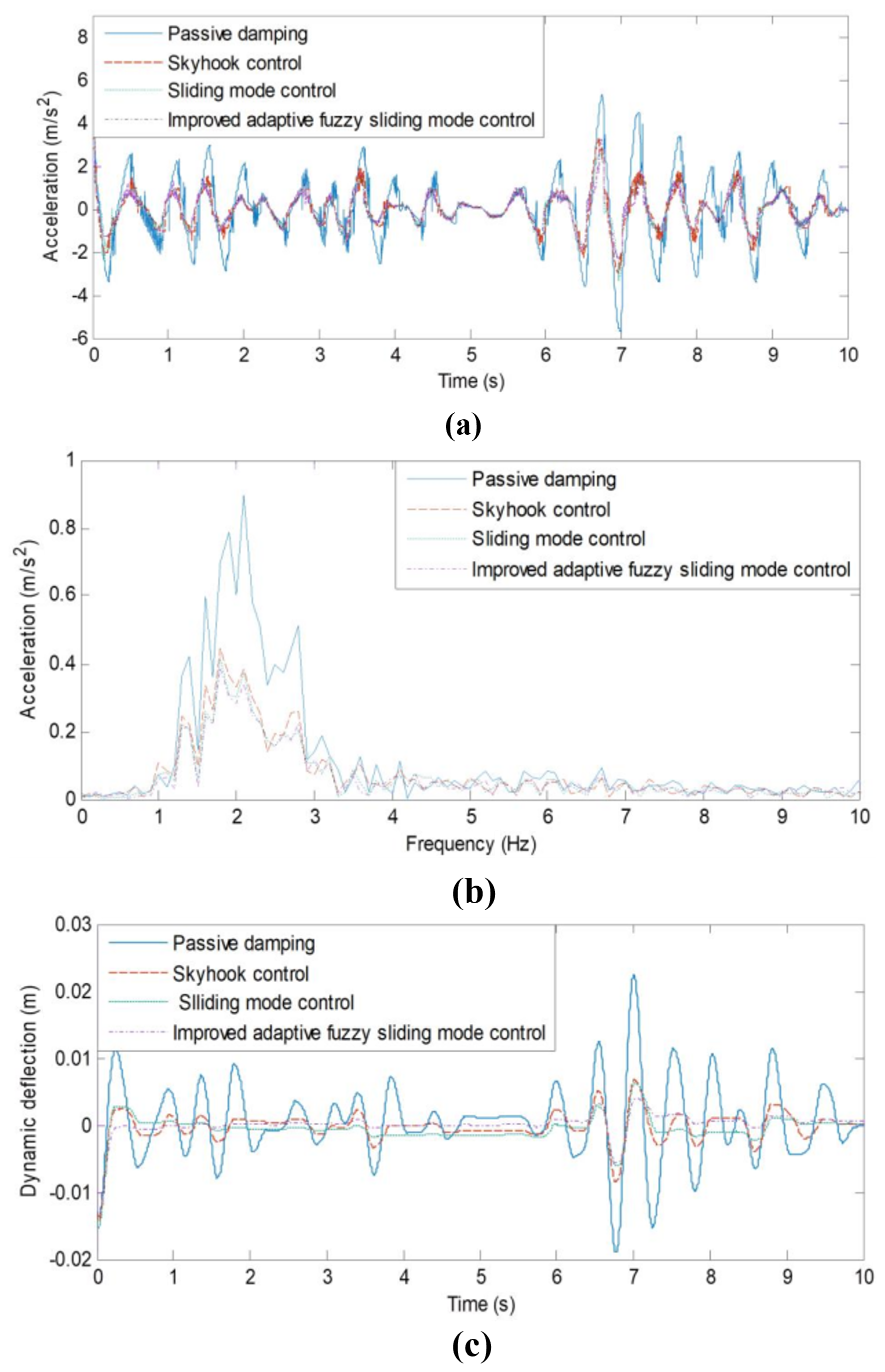
Figure 12Simulation results of random road excitation semi-active control. (a) Seat acceleration results, (b) seat acceleration frequency domain results, (c) dynamic deflection of seat suspension.
According to the Lyapunov stability criterion, the system is thus stable.
To obtain the traditional sliding-mode control law, it is first necessary to determine the perturbation fds generated by the model during the simplification process and external disturbances. In practical systems, this disturbance fds tends to be undetermined and cannot be given an accurate value, but it cannot be neglected either. In order to avoid affecting the control input f(t) of the system, it is therefore necessary to treat fds adaptively. The online estimation of fds is performed by designing a reasonable adaptive law to reduce its impact on the system performance. The adaptive control method is used to estimate the fds, and then the control law is given by
Substituting Eq. (23) into Eq. (17) yields
We define the Lyapunov function as follows: , and then
where, assuming that and , it can be obtained that
The adaptive law is chosen to be
where ; is the estimated value of fds; and γ is the parameter to be determined, with γ>0.
The sign function sgn(s) in Eq. (26) will aggravate the chattering phenomenon of the sliding-mode control; this discontinuity arises from the switching control. To mitigate this phenomenon, the hyperbolic tangent function tanh(s) is employed as a replacement for the sign function sgn(s) in the switching term, and it is represented as follows (Gao et al., 2004):
where σ is a positive constant, and its value dictates the rate at which the inflection points of the hyperbolic tangent function change. Replacing the discontinuous sign function with the smooth and continuous hyperbolic tangent function renders the switching process of sliding-mode control continuous, thereby enhancing the stability of the control system. The characteristics distinguishing the hyperbolic tangent function from the sign function are depicted in Fig. 9.
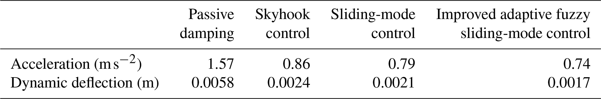
Table 2The rms value of acceleration and dynamic deflection under random seat excitation.
4.3 Fuzzy controller design
Owing to the advantages of strong robustness and high resistance to external interference, sliding-mode control finds diverse applications in the field of control. However, due to the “variable-structure” nature of sliding-mode control and its inherent control discontinuity, along with other characteristics, the whole control process produces chatter and instability. The fuzzy control method incorporates the expert control experience into the fuzzy controller through fuzzy logic reasoning and the fuzzy rule design. This control strategy does not require the construction of an accurate model of the controlled object, and so it is a commonly used method in solving the control of uncertainty systems. Therefore, in this paper, the fuzzy algorithm is employed to design a convergence law for sliding-mode control, ameliorating the chattering issue of the control system.
According to Eq. (18), when the moving point is close to the sliding-mode surface s=0, there is , which means that the convergence speed of the moving point when it reaches the sliding-mode surface is ε. When ε is chosen to be larger, the overshoot across the sliding-mode surface will be more significant, which will make the system vibrate violently, and the system will be unstable. Although a small value of ε can reduce the vibration, it will also slow down the convergence speed of the system. Therefore, to reduce the system's vibration and ensure the system's convergence speed, the value of k should be increased while decreasing ε. However, it can be seen from Eq. (20) that, when the motion point is faraway from the sliding-mode surface, too large a value of k will lead to a larger damping-force output from the semi-active damper. Due to the limited range of the semi-active damper's damping-force output, the value of k should not be selected to be too large. Considering the above factors, this paper uses fuzzy control to optimize the coefficients ε and k of the speed-reaching law in sliding-mode control and constructs a time-varying reaching law, which ensures the system's response speed while improving its stability. The fuzzy adaptive approach to design the convergence law is as follows:
where u1 and u2 are the fuzzy coefficients of ε and k in the speed reaching law. This can keep the speed-reaching law of sliding-mode control within a reasonable range at all times. We select a triangular membership function with overlap as the membership function for the input variable s and the output variables α1 and α2, as illustrated in Fig. 10.
In the figure, PB (positive large), PM (positive middle), PS (positive small), and ZO (zero) are fuzzy subsets. The absolute value of the sliding-mode function, denoted as |s|, serves as the input, leading to fuzzy output variables u1 and u2. The following four fuzzy rules are proposed:
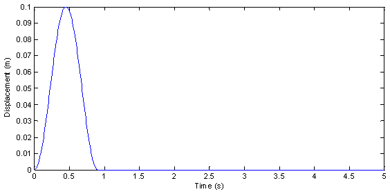
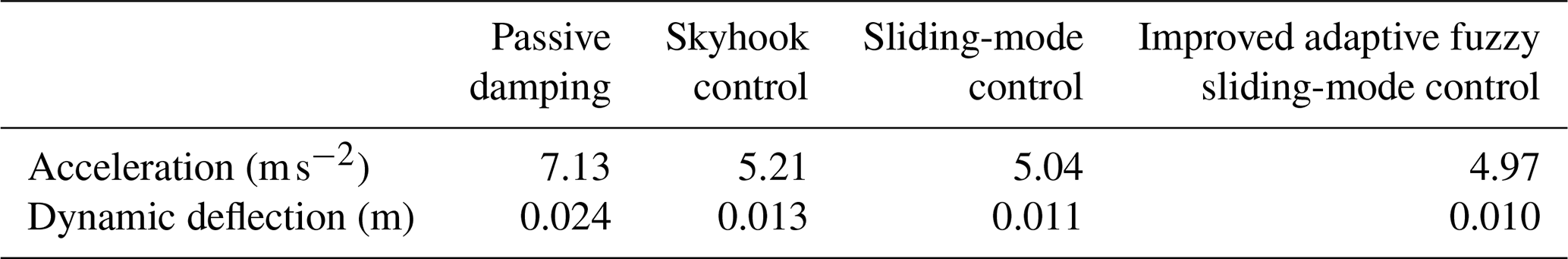
Table 3The peak-to-peak value of acceleration and dynamic deflection under random seat excitation.
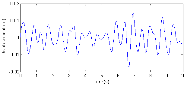
A random vertical vibration signal is applied to the vehicle cab floor to simulate the vibration excitation it experiences when the vehicle traverses uneven or rugged road surfaces. According to the ISO standard (ISO 7096, 2007), the random vertical vibration for the seat excitation input signal is generated based on the power spectral density of the seat excitation of a commercial vehicle, as shown in Fig. 11.
After establishing the vehicle seat's vibration excitation signal, this signal is inputted into the seat-damping suspension for simulation and analysis. Among the parameters that influence the performance of the seat suspension, the acceleration of the upper platform of the seat directly indicates the intensity of vibration transmitted to the vehicle driver and passengers. This parameter is the most crucial metric for evaluating seat suspension performance. The dynamic deflection of the suspension affects the displacement of the vehicle seat suspension; if this parameter is too large, it means that the seat suspension may frequently reach the maximum displacement, which affects the stability of the vehicle when driving. Therefore, the simulation analysis concentrates on both the acceleration of the seat upper platform and the dynamic deflection of the seat suspension.
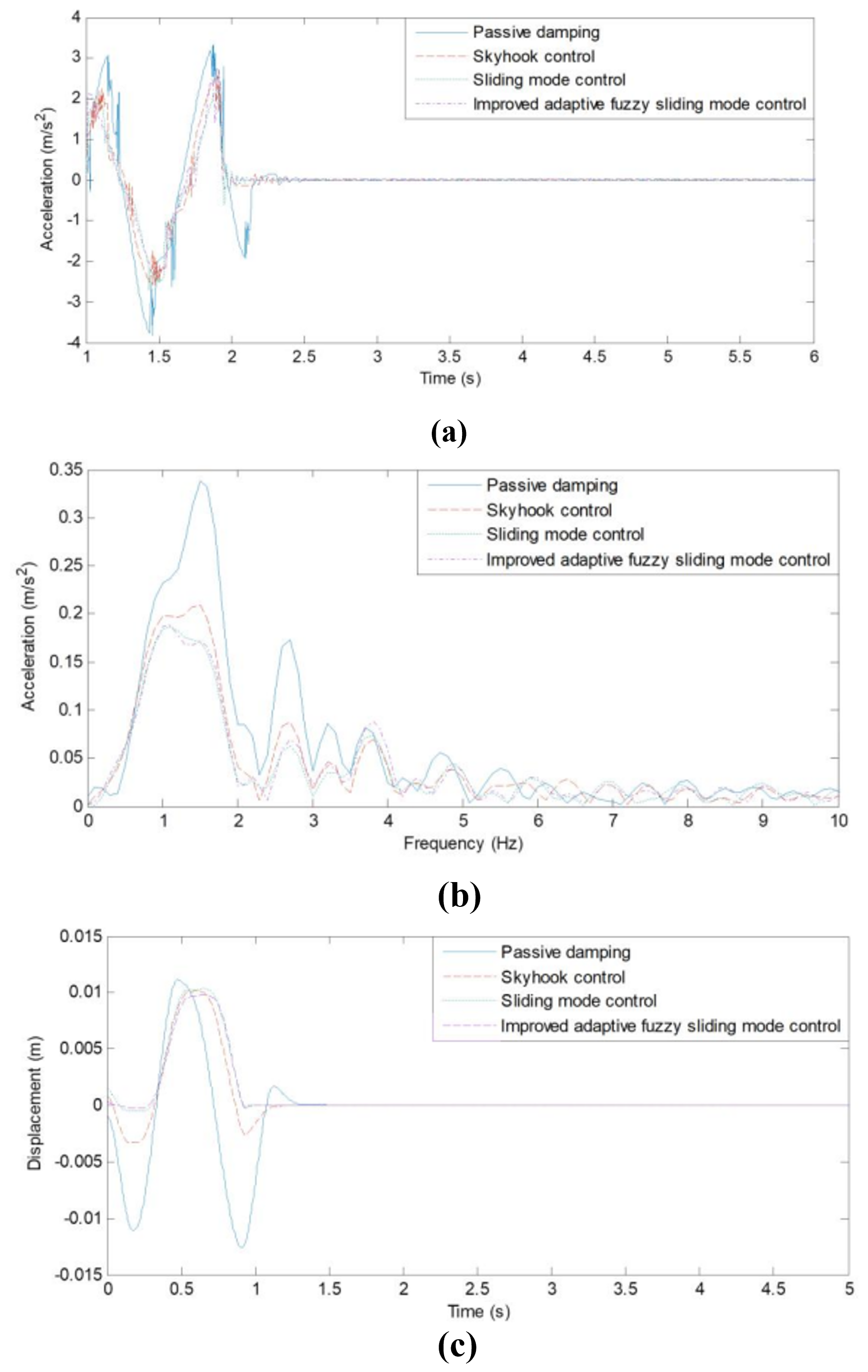
Figure 14Simulation results of pavement excitation semi-active control: (a) seat acceleration results, (b) seat acceleration frequency domain results, (c) dynamic deflection of seat suspension.
To substantiate the effectiveness of the control method presented in this paper, it was compared with passive damping, skyhook control, and sliding-mode control. The acceleration analysis results are shown in Fig. 12a, the acceleration frequency domain results are shown in Fig. 12b, and the dynamic deflection analysis results are shown in Fig. 12c.
Figure 12 shows that, under random vibration excitation, compared to passive control, skyhook control, sliding-mode control, and improved adaptive fuzzy sliding-mode control can all enhance the seat suspension's vibration reduction capability. From Fig. 12b, it can be seen that, in the sensitive low-frequency vibration range of the human body, compared to passive control, the three semi-active control methods can effectively reduce the seat's vibration acceleration and, with the improved adaptive fuzzy sliding-mode control, show the most obvious effect. Figure 12c reveals that, following the application of the three control methods, there is a significant reduction in the dynamic deflection of the seat suspension. Notably, when employing the improved adaptive fuzzy sliding-mode semi-active control method, the oscillation amplitude of the seat suspension dynamic deflection exhibits a smoother trend compared to the other methods.
Table 2 shows the root mean square (rms) values of seat acceleration and dynamic deflection using various control methods under random excitation. It can be seen from the table that, when the vehicle seat is subjected to random road excitation, the vibration acceleration values of the seat suspension using improved adaptive fuzzy sliding-mode control are reduced by 6.3 %, 14.0 %, and 52.9 %, and the dynamic deflection values are reduced by 19.0 %, 29.2 %, and 70.7 % compared to the sliding-mode control, skyhook control, and passive vibration damping, respectively. This indicates that the improved fuzzy sliding-mode semi-active control method established in this paper has significantly improved the comfort of vehicle seats.
Off-road vehicles are often subjected to impact excitation during operation when the vehicle cab will be accompanied by large-amplitude vibration, which has a very negative impact on the smoothness of the vehicle. Therefore, this paper uses a half-sine function to simulate the impact excitation experienced by the vehicle during the driving process. The excitation function is shown as follows:
In the above equation, Ar is the height of the obstacle encountered when the vehicle is traveling, L is the length of the obstacle, and v is the vehicle's traveling speed. In the impact excitation simulation analysis, the peak height of the road obstacle is selected as 0.1 m, the length of the obstacle pavement is 5 m, the speed of the vehicle is 20km h−1, and the impact pavement excitation signal is generated, as shown in Fig. 13.
Then, the impact excitation signal in the above figure is input into the seat damping suspension, and several methods of passive damping, skyhook control, sliding-mode control, and improved adaptive fuzzy sliding-mode control are used for simulation and analysis. The results of seat acceleration and suspension dynamic deflection on the seat under the control of different methods are shown in Fig. 14. According to the characteristics of impact vibration, the peak-to-peak values of vibration acceleration and suspension dynamic deflection are calculated for analysis, and the results are shown in Table 3.
From Fig. 14 and Table 3, it can be seen that, for vehicle impact excitation, the peak acceleration response of the seat suspension is significantly reduced after applying the three semi-active control methods. Specifically, when using skyhook control and sliding-mode control, the peak-to-peak values of seat suspension acceleration are reduced by 26.9 % and 29.31 %, respectively; meanwhile, the suspension dynamic deflection is reduced by 45.8 % and 54.1 %. After applying the improved adaptive fuzzy sliding-mode semi-active control method, the peak-to-peak acceleration is reduced by 30.3 % (compared with passive control), and the suspension dynamic deflection is reduced by 58.3 % – representing further improvements over skyhook control and sliding-mode control.
The aforementioned analysis results indicate that the improved adaptive fuzzy sliding-mode semi-active control method proposed in this paper outperforms both the skyhook semi-active control and the sliding-mode control methods.
For a 5-degree-of-freedom human seat suspension system, an improved adaptive fuzzy sliding-mode controller is developed for the simplified model, incorporating the dynamic model of the MRF damper into the control framework. This controller successfully mitigates the chattering issue associated with sliding-mode control, and it achieves favorable control results for the semi-active seat suspension system by utilizing the output damping force of the MRF damper. In summary, the following conclusions can be drawn:
- 1.
The 5-degree-of-freedom human-seat suspension system model is adaptively simplified, whereby the ideal skyhook control is adopted as the reference model, the dynamic error between the simplified model and the reference model is introduced into the sliding-mode design, and the MRF dynamic model is incorporated into the control system. On this basis, an adaptive sliding-mode controller is established.
- 2.
To address the issue of chattering in sliding-mode control, fuzzy control is harnessed to enhance the convergence law. This allows the system to dynamically adapt the convergence speed of the sliding point relative to the proximity to the sliding-mode surface. As a result, this approach effectively mitigates the undesired chattering in the system. The hyperbolic tangent function is selected to substitute the sign function in the convergence law switching term so that the system is more continuous during the convergence law switching process, which further reduces the chattering of the system.
- 3.
A seat suspension model with an MRF damper is established, and simulation analysis is carried out for the two working conditions of random excitation and impact excitation on the road surface. The analysis results show that the designed control algorithm improves the damping performance of the seat suspension system compared with passive damping, skyhook control, and sliding-mode control under different working conditions.
Data can be obtained from the corresponding author upon request.
Yabing Jing designed the control models, and Yongqin Liang developed the model code and performed the simulations. Teng Ma prepared the paper with contributions from all of the co-authors.
The contact author has declared that none of the authors has any competing interests.
Publisher's note: Copernicus Publications remains neutral with regard to jurisdictional claims made in the text, published maps, institutional affiliations, or any other geographical representation in this paper. The authors bear the ultimate responsibility for providing appropriate place names. Views expressed in the text are those of the authors and do not necessarily reflect the views of the publisher.
The authors sincerely appreciate the valuable time, suggestions, and comments of the editors and the reviewers, which improved the quality of the paper.
This research has been supported by the Natural Science Foundation of Hebei Province (grant no. E2024202169), Science and Technology Projects of XizangAutonomous Region, China (grant no. XZ202501YD0010), and the National Natural Science Foundation of China (grant no. 52305257).
This paper was edited by Liangliang Cheng and reviewed by two anonymous referees.
Bai, X. X., Jiang, P., and Qian, L. J.: Integrated semi-active seat suspension for both longitudinal and vertical vibration isolation, J. Intell. Mater. Syst. Struct., 28, 1036–1049, https://doi.org/10.1177/1045389X16666179, 2016.
Bouc, R.: A mathematical model for hysteresis, Acta Acust., 24, 16–25, 1976.
Choi, S. B., Lee, S. K., and Park, Y. P.: A hysteresis model for the field-dependent damping force of a magnetorheological damper, J. Sound Vib., 245, 375–383, https://doi.org/10.1006/jsvi.2000.3539, 2001.
Deng, L., Sun, S., Christie, M., Ning, D., Jin, S., Du, H., Zhang, S., and Li, W.: Investigation of a seat suspension installed with compact variable stiffness and damping rotary magnetorheological dampers, Mech. Syst. Signal Process., 171, 108802, https://doi.org/10.1016/j.ymssp.2022.108802, 2022.
Du, X. M., Yu, M., Fu, J., Peng, Y. X., and Zhang, H.: H∞ control for a semi-active scissors linkage seat suspension with magnetorheological damper, J. Intell. Mater. Syst. Struct., 30, https://doi.org/10.1177/1045389x18778340, 2019.
Gao, D. X., Sun, Z. Q., and Wang, W.: Adaptive fuzzy sliding mode control for robotic manipulators, in: 8th World Congress on Intelligent Control and Automation (WCICA), 4811–4816, https://doi.org/10.1109/wcica.2010.5554667, 2004.
Gao, Z. J., Wong, P. K., and Zhao, J.: Design of compensatory backstepping controller for nonlinear magnetorheological dampers, Appl. Math. Model., 114, 318–337, https://doi.org/10.1016/j.apm.2022.10.001, 2023.
Hu, G. L., Liu, Q. J., Ding, R. Q., and Li, G.: Vibration control of semi-active suspension system with magnetorheological damper based on hyperbolic tangent model, Adv. Mech. Eng., 9, 1–15, https://doi.org/10.1177/1687814017694581, 2017.
Hu, L. J., Liu, B., Huan, R. H., Zhu, W. Q., and Liu, Y.: Optimal semi-active control of nonlinear random vibration of armored vehicle seats, J. Vib. Shock, 39, 220–224, https://doi.org/10.13465/j.cnki.jvs.2020.23.031, 2020 (in Chinese).
ISO 7096: Earth-moving machinery—Laboratory evaluation of operator seat vibration, American National Standards Institute, New York, NY, USA, 2007.
Kwok, N. M., Ha, Q. P., Nguyen, T. H., Li, J., and Samali, B.: A novel hysteretic model for magnetorheological fluid dampers and parameter identification using particle swarm optimization, Sens. Actuators A Phys., 132, 441–451, https://doi.org/10.1016/j.apm.2022.10.001, 2006.
Liu, H., Nonami, K., and Hagiwara, T.: Active following fuzzy output feedback sliding mode control of real vehicle semi-active suspensions, J. Sound Vib., 314, 39–52, https://doi.org/10.1016/j.jsv.2008.01.032, 2008.
Maciejewski, I.: Control system design of active seat suspensions, J. Sound Vib., 331, 1291–1309, https://doi.org/10.1016/j.jsv.2011.11.010, 2012.
Morales, A. L., Nieto, A. J., and Chicharro, J. M.: A semi-active vehicle suspension based on pneumatic springs and magnetorheological dampers, J. Vib. Control, 24, 808–821, https://doi.org/10.1177/1077546316653004, 2018.
Rosli, R., Mohamed, Z., and Priyandoko, G.: Simulation of active force control using MR damper in semi active seat suspension system, IOP Conf. Ser.: Mater. Sci. Eng., 1062, 012005. https://doi.org/10.1088/1757-899X/1062/1/012005, 2021.
Shen, Y., Ren, H., Zhang. S., Lin, J., Yang, X., and Liu, Y.: Vehicle semi-active air inerter-spring-damper suspension with frequency-varying negative stiffness: design, control, and experimental validation, Mech. Syst. Signal Process., 244, 113740, https://doi.org/10.1016/j.ymssp.2025.113740, 2026.
Song, X., Ahmadian, M., Southward, S., and Miller, L. R.: An adaptive semiactive control algorithm for magnetorheological suspension systems, J. Vib. Acoust., 127, 493–502, https://doi.org/10.1115/1.2013295, 2005.
Stanway, R., Sproston, J. L., and Stevens, N. G.: Non-linear modelling of an electro-rheological vibration damper, J. Electrostat., 20, 167–184, 1987.
Sun, B., Wang, J., Lin, J., Gao, M., and Gu, Y.: Research on airborne active and passive composite vibration isolation optoelectronic stabilization platform system, IOP Conf. Ser. Mater. Sci. Eng., 452, https://doi.org/10.1088/1757-899X/1062/1/012005, 2018.
Sun, S. S., Yang, J., Deng, H. X., Du, H., and Nakano, M.: Horizontal vibration reduction of a seat suspension using negative changing stiffness magnetorheological elastomer isolators, Int. J. Veh. Des., 68, 104, https://doi.org/10.1088/1757-899X/452/4/042042, 2015.
Sun, S. S., Ning, D. H., Yang, J., Du, H., Zhang, S. W., and Li, W. H.: A seat suspension with a rotary magnetorheological damper for heavy duty vehicles, Smart Mater. Struct., 25, 10, https://doi.org/10.1088/0964-1726/25/10/105032, 2016.
Wang, J., Wang, X., Wang, Q., Ni, T., Zhang, L., and Zhang, H.: Low-complexity prescribed performance control of hydraulic active suspension systems for intelligent vehicles, Control Eng. Pract., 167, 106649, https://doi.org/10.1016/j.conengprac.2025.106649, 2026.
Wang, L., Yang, Z., Chen, X., Zhang, R., and Zhou, Y.: Research on adaptive speed control method of an autonomous vehicle passing a speed bump on the highway based on a genetic algorithm, Mech. Sci., 13, 647–657, https://doi.org/10.5194/ms-13-647-2022, 2022.
Wang, X., Bi, F., and Du, H.: Reduction of low frequency vibration of truck driver and seating system through system parameter identification, sensitivity analysis and active control, Mech. Syst. Signal Process., 105, 16–35, https://doi.org/10.1016/j.ymssp.2017.12.006, 2018.
Wen, Y. K.: Method for random vibration of hysteretic systems, J. Eng. Mech. Div., 102, 249–263, 1976.
Yang, C. G., Yang, X. L., and Zhou, Y. M.: Research on the performance of magnetorheological semi-active suspension with stepped by-pass valve based on fuzzy PID control, J. Magn., 28, 277–285, https://doi.org/10.4283/JMAG.2023.28.3.277, 2023a.
Yang, H., Liu, Q., Zhang, Y., and Yu, F.: An adaptive sliding mode fault-tolerant control for semi-active suspensions with magnetorheological dampers based on t-s fuzzy vehicle models, J. Vib. Control, 29, 251–264, https://doi.org/10.1177/10775463211046670, 2023b.
Yin, W., Ding, J., and Qiu, Y.: Nonlinear dynamic modelling of a suspension seat for predicting the vertical seat transmissibility, Math. Probl. Eng., 2021, https://doi.org/10.1155/2021/3026108, 2021.
Yu, J., Dong, X., Wang, X., Li, J., and Li, B.: Design, modeling, and control of a magnetorheological rotary damper for scissor seat suspension, Proc. Inst. Mech. Eng. Part D: J. Automob. Eng., 234, 095440702090384, https://doi.org/10.1177/0954407020903849, 2020.
Zhao, Y., Alashmori, M., Bi, F., and Wang, X.: Parameter identification and robust vibrationcontrol of a truck driver's seat system using multi-objective optimization and genetic algorithm, Appl. Acoust., 132, 107697, https://doi.org/10.1016/j.apacoust.2020.107697, 2021.