the Creative Commons Attribution 4.0 License.
the Creative Commons Attribution 4.0 License.
 | 23 Mar 2026
Numerical analysis of molten-pool behavior during selective laser sintering for improving the performance of polycaprolactone bone scaffold
Jinzhe Wu
Jian Han
Xiaofeng Li
Zhiyuan Ma
Polycaprolactone (PCL) bone scaffolds fabricated by selective laser sintering (SLS) have great potential for repairing bone defects. Appropriate porosity and sufficient mechanical strength are important characteristics of ideal bone scaffolds. These characteristics are closely related to the SLS process parameters, including laser power, scanning speed, preheating temperature, powder layer thickness, and scanning spacing. However, there is still a lack of theoretical research from the perspective of molten-pool analysis on how SLS process parameters affect the performance of PCL scaffolds. Because of the short interaction time, extremely small dimensions, and complex process, it is very difficult to evaluate the behavior of the molten pool, especially for PCL, and it is necessary to consider Marangoni flow and its viscoelastic characteristics. In this study, the behavior of a PCL molten pool with three different energy densities (Ed) was simulated considering the Marangoni flow and viscoelastic characteristics. Three PCL scaffolds with different Ed values were prepared, and their porosity, mechanical strength, and microstructure were comprehensively evaluated. The results indicated that an appropriate increase in Ed resulted in an increased depth of the molten pool, a decrease in porosity, and strengthened mechanical properties. This study provides new knowledge for understanding and optimizing the performance of SLS-prepared scaffolds.
- Article
(2326 KB) - Full-text XML
- BibTeX
- EndNote


Reconstructing bone defects caused by trauma, severe infection, tumor resection, and congenital abnormalities is a significant challenge in orthopedic treatment (Yang et al., 2018). Orthopedic surgeons commonly use autologous and allogeneic bone grafts to repair bone defects. Although autologous bone transplantation is a commonly used technique, it has limitations. However, this procedure is often hindered by issues such as a limited supply of autologous bone, as well as the potential for inflammation, infection, and chronic pain resulting from the secondary operation. Conversely, allografts pose their own set of challenges, including histocompatibility issues and the possibility of reduced bone inductivity after undergoing radiation or freeze-drying, which can ultimately lead to surgical failure (Fu et al., 2013; Ma et al., 2018).
Bone tissue engineering has emerged as a promising solution for bone defects and has undergone extensive development in recent decades. This process involves culturing seed cells in vitro on three-dimensional porous scaffolds for continuous culture, promoting the formation of new bone, and ultimately repairing the bone defect (Zhang et al., 2019). The success of bone tissue engineering relies on the ability of bone tissue scaffolds to induce bone cell growth. An ideal scaffold should possess excellent biocompatibility, surface activity, and mechanical properties and exhibit appropriate porosity and pore size to promote vascularization. This enables the provisioning of the oxygen and nutrients necessary for cell growth (Zhang et al., 2017).
Bone tissue scaffolds can be prepared using traditional methods or additive manufacturing (AM) technology. Traditional preparation methods include electrospinning, solvent casting, particulate leaching, and gas foaming (Rajzer et al., 2018; Hu et al., 2019). Although these methods can successfully prepare scaffolds, it is difficult to preserve accuracy in microstructure control while providing a customized geometry and sufficient mechanical strength. The emergence of AM technology can overcome these obstacles. The main AM technologies include fused deposition modeling (FDM), stereo lithography appearance (SLA), and selective laser sintering/modeling (SLS/M). Among these, SLS technology is a method for selectively sintering a powder layer by layer using the laser energy and finally forming parts (Du et al., 2017). Compared with other AM technologies, SLS technology has the advantages of a wide range of applied materials, high precision, no need for support, and suitability for constructing complex pore structures. Moreover, because it is based on powder manufacturing, bone tissue scaffolds manufactured using SLS technology have rough roughness, which promotes cell attachment, proliferation, and differentiation (Chen et al., 2014; Sun et al., 2021).
In addition to the processing method, the material of the scaffold is another key factor for its success (Koons et al., 2020). Currently, metal, polymer (natural or artificial), inorganic materials, composite materials, etc. are widely used in scaffold materials (Cuadrado et al., 2017; Hua et al., 2021). Among these, polymer materials are favored by researchers because of their biodegradability (Zhang et al., 2020; Stuckensen et al., 2018). Polycaprolactone (PCL), a synthetic polymer approved by the Food and Drug Administration (FDA), has excellent biocompatibility, biodegradability, thermal stability, and machinability, making it a popular scaffold material. Many researchers have attempted to prepare PCL scaffolds using SLS technology. However, the selection and optimization of SLS processing parameters – such as laser power, scanning speed, preheating temperature, powder layer thickness, and scanning spacing – to obtain superior scaffold performance has become a challenge. Williams et al. (2005) changed the laser power from 1 to 7 W, with a fixed scanning speed (3810 mm s−1) and preheating temperature (40∘), to determine the most appropriate laser power for PCL (Williams, et al., 2005). Partee et al. (2006) optimized the SLS parameters of PCL through systematic experiments, and the final dimensional accuracy was maintained at 3 %–8 %, and the density reached 94 % (Partee et al., 2006). In the latest study, Tortorici et al. (2021) not only considered the dimensional accuracy but also took the mechanical properties of the scaffold as the evaluation standard in the process of optimizing PCL parameters (Tortorici et al., 2021).
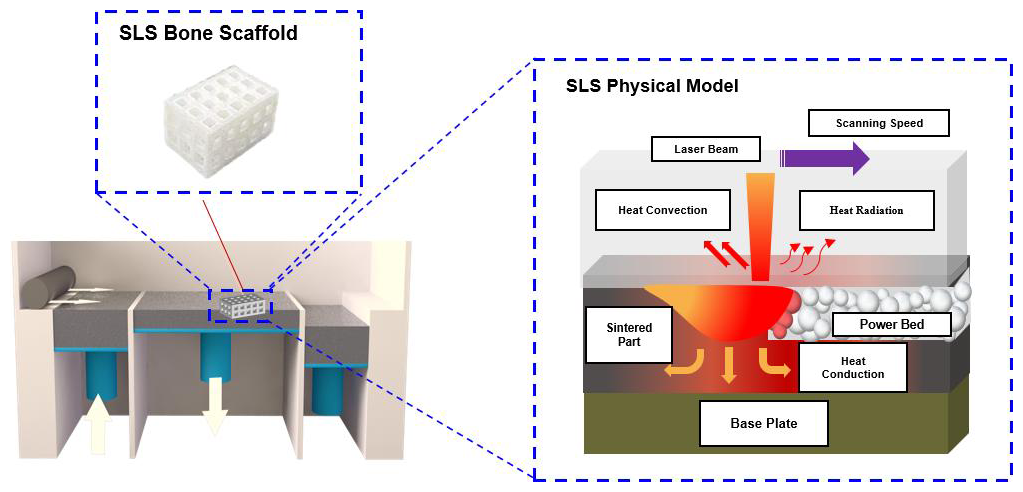
Although many studies have been conducted on the SLS parameter of PCL, they rely on experimental methods. In SLS, the laser energy is absorbed by the powder, which melts and forms a molten pool (Wu et al., 2018). Therefore, it is advisable to optimize the SLS process parameters of PCL from the molten-pool perspective. Owing to the extremely small molten-pool dimensions of several tens of micrometers, as well as the laser powder interaction time, the powder melting and consolidation time are extremely short, making it challenging to assess the quality of sintered parts by directly observing the molten pool. In the current study, numerical simulations were used to solve this problem. The SLS process is very complex and involves heat conduction, radiation, convection, and “Marangoni” convection (driven by the temperature gradient on the molten-pool surface), as schematically shown in Fig. 1. Li et al. (2010) studied the scan track features, densification, and tensile properties of SLS-fabricated 316 L stainless steel samples at different scan speeds. Yang et al. (2016) studied the relationship between the relative density, microstructures, microhardness, and tensile properties of SLM Ti-6Al-4V single-track and SLM processing parameters from a molten-pool perspective.
To the best of the authors' knowledge, most research on molten pools has focused on metal materials, and there has been little research on polymer materials. However, it is worth noting that, compared with metals, polymer materials have many different properties, with the most obvious being that they have the viscoelasticity of non-Newtonian fluids. For Newtonian fluids, the material viscosity is mainly affected by temperature; however, for non-Newtonian fluids, the material viscosity is also affected by shear stress. Viscosity is a key parameter in molten-pool simulation; therefore, it is necessary to consider the viscoelasticity of the polymer in the process of molten-pool simulation.
In this study, to optimize the SLS processing parameters for preparing PCL bone scaffolds with excellent performance, a simulation model that considers the influence of “Marangoni” convection and viscoelasticity was constructed, and the thermal behaviors and physical mechanisms of the molten pool with different energy densities were investigated. Finally, the porosity, mechanical strength, and microstructure of the PCL scaffolds were comprehensively evaluated. The simulation results were in good agreement with the experimental results. This study clarified the process–molten-pool–scaffold performance correlation and facilitated the effective production of bone scaffolds.
2.1 Characterization of PCL
The PCL powder used in this study (CAPA® 6500 PCL) was purchased from Solvay (Belgium). The mean particle size of the PCL powder was determined using a Mastersizer instrument (Malvern, Mastersizer 2000, UK). Differential scanning calorimetry (DSC, TA, Q2000, USA) and a thermogravimetric analyzer were used to determine the thermodynamic properties of the PCL powder (TGA, TA, Q5000, USA) at a heating rate of 10 °C min−1.
2.2 Model and mesh
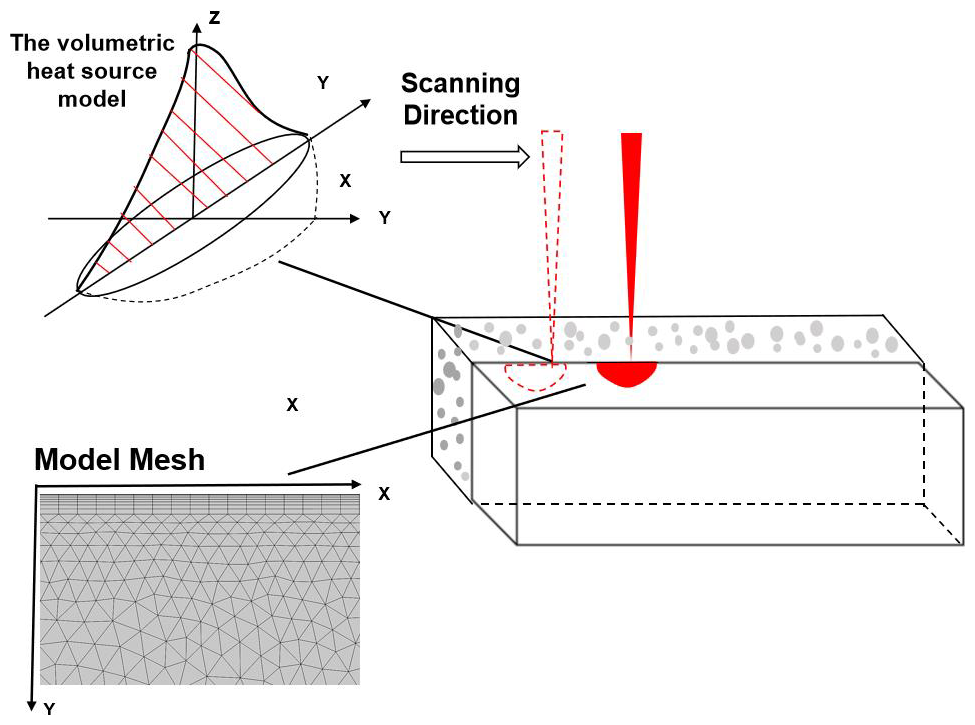
Considering the visibility within the molten pool and the computational efficiency, a two-dimensional cross-sectional model was established in this study (Li et al., 2021; Nandi et al., 2022). Figure 2 shows a schematic of the laser scanning. The X axis shows the laser-scanning direction, and the Y axis shows the depth of a series of pools. The powder bed was meshed according to the absorption characteristics of the laser bed. To improve the simulation efficiency, the size of the rectangular mesh above the model was set to be larger; with an increase in depth, the temperature decreased slowly, and the triangular mesh size became smaller.
2.3 The volumetric heat source model
The heat source model can be divided into concentrated, plane, and volume distribution heat source models. In this study, a double-ellipsoid geometric model was used to describe the laser-sintering process, as shown in Fig. 2. The adoption of the double-ellipsoidal heat source model in this study's simulation of the selective-laser-sintering (SLS) process for polycaprolactone (PCL) powder stems fundamentally from its significant advantages in capturing the physical essence of the interaction between a moving laser beam and the powder bed. Although the classical Gaussian surface heat source is widely employed, it assumes uniform energy deposition solely at the surface. This assumption inadequately represents the actual three-dimensional energy distribution profile arising from the multiple scattering and absorption phenomena of the laser beam within the powder volume. Critically, it fails to accurately depict the pronounced thermal gradient asymmetry inherent in the melt pool along the scanning direction. The double-ellipsoidal model addresses these limitations by geometrically decoupling the heat source into front and rear semi-ellipsoids, thereby enabling the independent definition of their energy distribution parameters. This structure permits a more physically realistic simulation of the laser energy penetration behavior into the powder and/or molten material and the consequent asymmetric temperature field: specifically, the steep thermal gradient ahead of the laser (corresponding to the front ellipsoid) and the trailing heat-affected zone behind the melt pool (corresponding to the rear ellipsoid). This capability is paramount for predicting PCL's melting morphology, melt pool dimensions, solidification behavior, and potential residual thermal stresses and distortions of PCL as the sintering quality of PCL is highly dependent on the precise control of the local thermal history. Furthermore, compared to more complex volumetric heat source models (e.g., conical–ellipsoidal combinations), the double-ellipsoidal model achieves a critical balance: it maintains computational accuracy for key physical phenomena – specifically, the spatial inhomogeneity and directional asymmetry of energy deposition – while retaining relatively lower computational complexity. The energy equation of the volumetric heat source model is as follows:
where a, b, and c are the heat source shape parameters; t is the sintering time; and τ is the time delay factor.
2.4 Governing equations and initial boundary conditions
The interaction between the laser and PCL powder is a complex physical process. In the system, heat conduction occurs between the powders, heat convection, and heat radiation between the powder bed and the surrounding atmosphere. In this study, all three heat transfer mechanisms were considered. For the convenience of the simulation, the following assumptions were made in this study:
-
The PCL powder bed was continuous and uniform. When the temperature reaches its melting point, PCL undergoes a sudden transition from the granular state into the liquid state.
-
In the melting process, we assumed that the thermophysical parameters of PCL were independent of temperature.
-
The loss of mass and heat due to vaporization was ignored.
-
We assumed that the base of the model was adiabatic owing to the limited heat-affected zone of the laser in the depth direction.
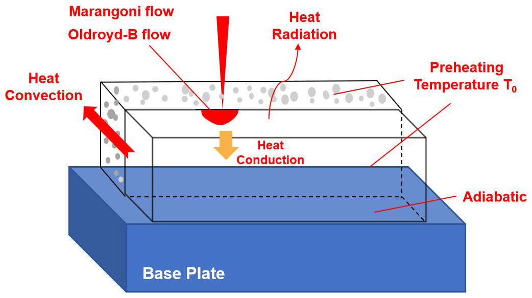
A schematic of the computational model and its boundary conditions is shown in Fig. 3.
Heat transfer in the SLS process is expressed by the “energy conservation equation”:
where C is the heat capacity (J (kg K)−1), T is the real-time temperature (K), K is the thermal conductivity of the powder material (W mK−1), and Qunit is the energy conversion rate per unit volume (W m−3).
When t=0, the initial temperature distribution is the preheating temperature T0, which can be expressed as
The boundary conditions of the top surface of the powder bed can be expressed as follows:
where n is the surface normal vector, q is the heat flux (W m2), and Q0 is the energy provided by the laser.
The lower surface is assumed to be adiabatic, and the boundary conditions can be expressed as follows:
The boundary conditions on the other side of the powder bed are as follows:
where h is the convective heat transfer coefficient, and Tamb is the ambient temperature, which is equal to the preheating temperature T0.
The flow field of the molten pool in the SLS process is represented by the “momentum conservation equation” and the “mass conservation equation”:
where u is the velocity (mm s−1), P is the pressure (Pa), I is the unit direction vector, F is the physical force (N), and g is the gravitational acceleration (m s2).
According to the actual situation, the bottom surface of the powder bed and the surface on both sides were set to “no sliding.” The boundary conditions of the top surface of the powder bed are characterized by Marangoni flow.
2.5 Marangoni flow
Due to the action of the thermal gradient or chemical capillary force, Marangoni flow is generated on the surface of the fluid, causing the liquid to flow from the position of low surface tension to the position of high surface tension. The governing equation describing the Marangoni flow is as follows:
where η is the dynamic viscosity (m2 s−1), and γ is the Marangoni flow coefficient (N mK−1).
2.6 Oldroyd-B flow
The Oldroyd-B model is extensively used to predict various instabilities in the shear flow of viscoelastic fluids, typically achieved experimentally using polymer solutions (Castillo Sánchez et al., 2022). The main expressions are as follows:
where η is the dynamic viscosity (m2 s−1), λ is the Marangoni flow coefficient (N mK−1), ut expresses the speed u as a function of time t, and σ represents the Cauchy stress tensor.
2.7 The melting and solidification model
Within the integrated modeling approach based on a transient thermomechanical coupling framework employed in this study to simulate the melting and solidification behavior of polycaprolactone (PCL) powder during selective laser sintering, the melting process is addressed using the enthalpy–porosity methodology to dynamically track the phase change interface, wherein the liquid fraction evolution within the characteristic PCL-melting temperature range is calculated through a temperature-dependent latent heat absorption function (Tolochko et al., 2003). The core of the solidification model is characterizing the non-isothermal crystallization kinetics of semicrystalline PCL as its recrystallization behavior directly dictates the final part's properties, utilizing the Nakamura equation derived from the Kolmogorov–Avrami–Evans phase transformation theory to represent the temperature-dependent crystallization rate. The main expression is as follows:
where α is the relative crystallinity, T is the temperature (°C), t is the time (s), K(T) is the crystallization rate function, and n is the Avrami exponent.
2.8 Establishment of scaffold mode
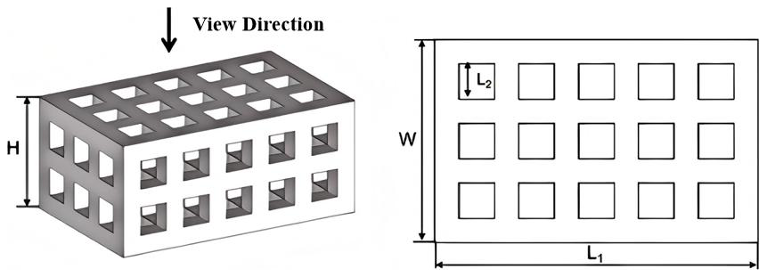
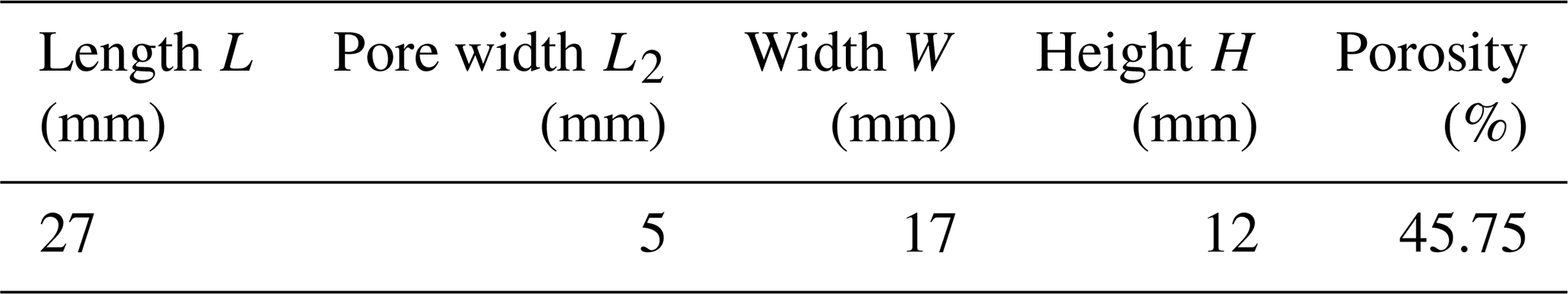
In this study, Magics 21.0 software (Materialize, Belgium) was used to design a cuboid bone tissue scaffold with square voids, as shown in Fig. 4. The size and porosity of the model are listed in Table 1. The file was saved in the STL file format.
2.9 Selective laser-sintering process of scaffolds
To consider the comprehensive influence of the SLS process, including laser power (P), scanning speed (V), layer thickness (H), and hatch space (D), on the properties of the scaffolds, the energy density (Ed) was used as follows:
Three different energy densities (Ed1, Ed2, and Ed3) were chosen by varying the laser power to 2, 4, and 6 W, respectively, with the same scanning speed of 1500 mm s−1. The main process parameters are listed in Table 2. The scaffolds were fabricated successfully using HK P500 (Huazhong University of Science and Technology, Wuhan, China). Before removal from the powder bed, these scaffolds were held at room temperature (25 °C) for 2 h. The unsintered powders on the surface and in the pores were blown away using a high-power blower.
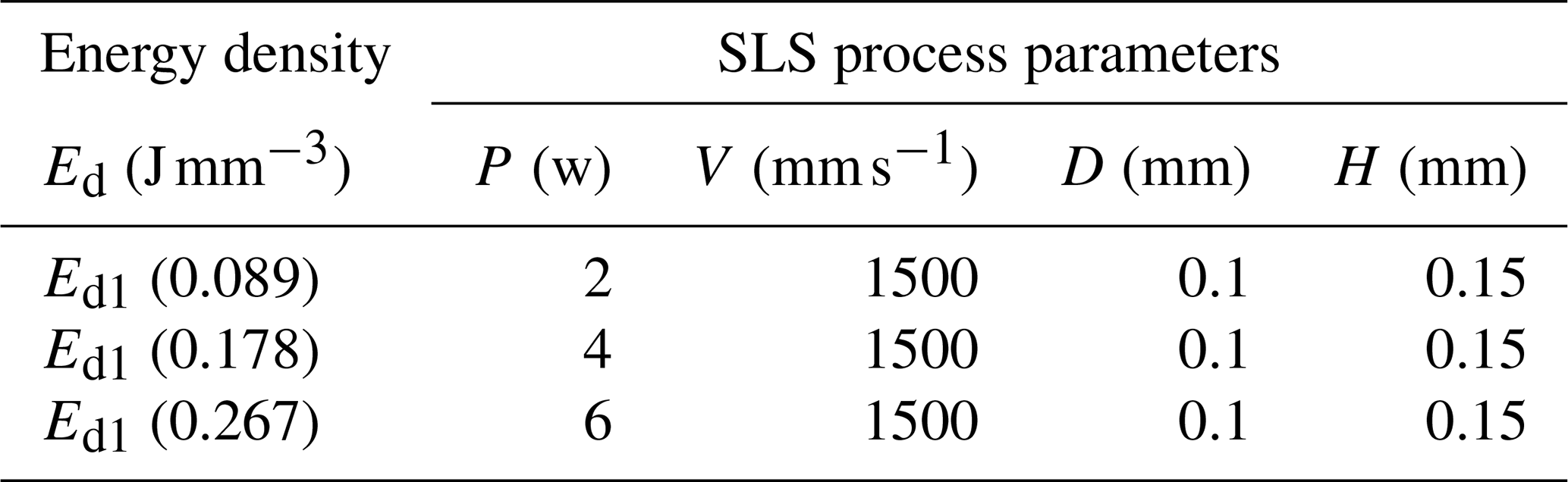
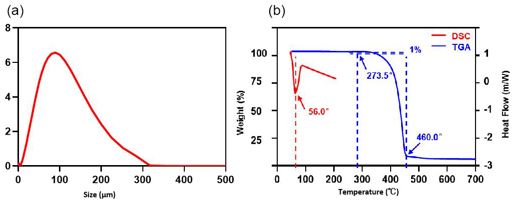
Figure 5Properties of PCL powder. (a) Size distribution of PCL powders. (b) DSC and TGA analyses of PCL powder.
3.1 PCL powder characterization
For the SLS method, the particle size distribution range of the powder is closely related to the properties of the sintered part. If the powder particle size is too small, it will easily cause the powder agglomeration effect; on the other hand, if the powder particle size is too large, it will hinder the powder flow. Figure 5a shows the particle size distribution curve of the PCL material. It can be seen from the figure that the particle size distribution of PCL presents a good symmetry, and the average diameter of PCL particles is about 100 µm. The thickness of the powder was set to 0.15 mm considering the fact that a small powder size would cause agglomeration, while an excessive powder size would affect the powder-spreading process.
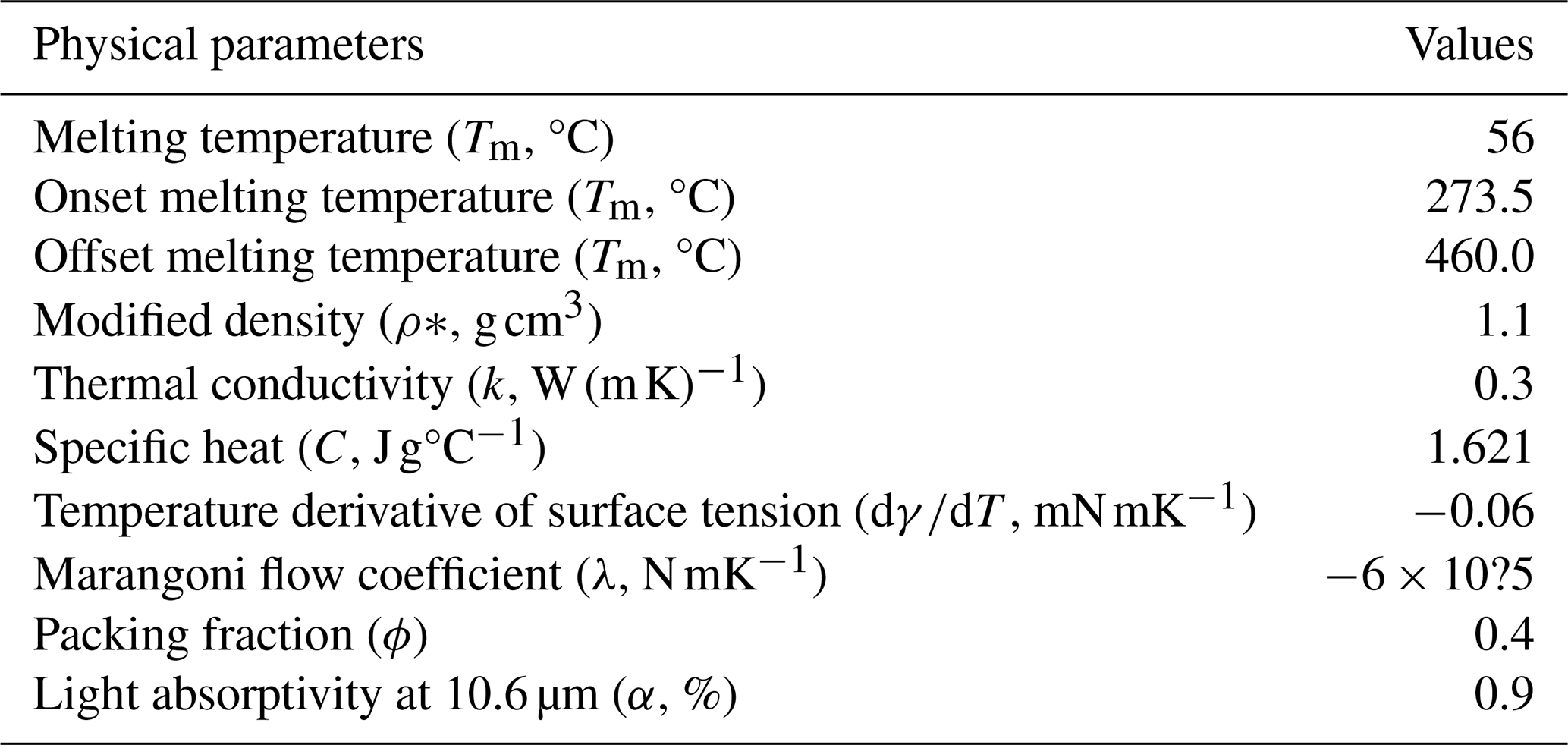
In the simulation experiment of the molten pool, the melting point (Tm), initial degradation temperature (the temperature corresponding to 10 % material weight loss, Tds), and final degradation temperature (Tdf) of the PCL material are all important parameters. The DSC (red line) and TGA (blue line) results of PCL are shown in the figure. As shown in the Fig. 5b, the melting temperature of the molten pool Tm was 56 °C, the initial degradation temperature Tds was 273.5 °C, and the final degradation temperature Tdf was 460 °C. Generally, the preheating temperature of the powder bed is 3–15 °C lower than the melting point of the material; therefore, the preheating temperature was set to 40 °C in this experiment. The other key physical parameters of PCL were derived from the literature and are listed in Table 3 (Huang et al., 2018; Zhuravlevet al., 2011).
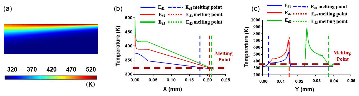
Figure 6Relationship between the processing parameters and temperature distribution of the molten pool. (a) Temperature field of the molten pool at Ed1 (t = 1.6 ms); (b) transient temperature distribution along the depth direction (Y axis) with different laser energy densities Ed1–Ed3; (c) transient temperature distribution along the depth direction (X axis) with different laser energy densities Ed1–Ed3.
3.2 Relationship between processing parameters and physical fields of the molten pool
3.2.1 Temperature field distribution
Through the simulation experiment, the distributions of the molten-pool temperature, velocity, phase transition, and stress fields with three different energy densities were obtained. The temperature field of the energy density Ed3 (t = 1.6 ms) is shown in Fig. 6a. As can be seen from the figure, owing to the heat accumulation effect of the molten pool, the highest temperature of the molten pool was approximately 520 °C in the center of the molten pool. In addition, because the scanning speed of the laser is much higher than the solidification rate of the molten pool, a “comet-like” tail of the molten pool appears, indicating that the temperature gradient at the front of the molten pool is larger.
As shown in Fig. 6b, the transient temperature distribution along the depth direction (X axis; horizontal line, Y = 4 × 10⁻⁴, t = 1.6 ms) varies with different laser energy densities. With the increase in energy density, the corresponding temperature field temperature also rises: when the energy density is Ed1, the highest temperature of the molten pool is approximately 374.5 °C. When the energy density is Ed3, the highest temperature of the molten pool is approximately 491.2 °c. The dotted red line represents the melting point of the PCL. According to the intersection of this dotted red line and this temperature curve, we can calculate the length of the molten pool (l).
Figure 6c shows the instantaneous temperature field distribution along the Y direction with three energy densities (vertical line, X = 6 × 10⁻⁴, t = 1.6 ms). We can also conclude that, with an increase in energy density, the corresponding temperature field temperature also increases. In this figure, the intersection of this dotted red line (PCL melting point) and the temperature curve indicates the depth of the molten pool. In the SLS process, the depth of the molten pool x must be less than the thickness of each powder layer; otherwise, the sintered parts will exhibit obvious stratification. Therefore, according to the depth of the molten pool shown in Fig. 6c, it can be inferred that the powder thickness should not be greater than 0.15 mm.
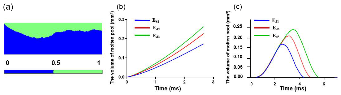
Figure 7Relationship between processing parameters and molten-pool geometry. (a) The molten-pool geometry of the molten pool at Ed3 (t = 1.6 ms). (b) Relationship between the total volume of the molten pool and time in the entire sintering process. (c) Volume of molten-pool curves in the range of x = 1 × 10⁻⁴ to x = 4 × 10⁻⁴ (y = 4 × 10⁻⁴) with different Ed.
3.3 Molten-pool geometry
Figure 7 shows the change in the molten-pool volume with different energy densities. The molten-pool volume of energy density Ed3 (t = 1.6 ms) is shown in Fig. 7a. The blue and green areas represent the solid and molten PCL, respectively. Figure 7b shows the relationship between the total molten-pool volume and time during the entire sintering process. As shown in the figure, an increase in energy density leads to an increase in the molten-pool volume. In Fig. 7c, a fixed region (X = (1 × 10⁻⁴, 4 × 10⁻⁴), Y = 4 × 10⁻⁴) was selected to evaluate the volume change of the molten pool at different energy densities. As shown in Fig. 7c, the volume curve of each group of molten pools starts to rise with the input of energy and then shrinks with cooling and solidification.
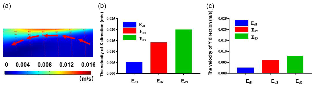
Figure 8Relationship between the processing parameters and velocity field of the molten pool. (a) Magnitude and direction of the flow velocity in the molten pool. (b) Influence of Ed on the average flow velocity of the molten pool (X direction). (c) Influence of Ed on the average flow velocity of the molten pool (Y direction).
3.4 Molten-pool velocity field
Furthermore, the distribution of the velocity field in the molten pool was simulated to observe the direction of the Marangoni flow, as shown in Fig. 8. As shown in Fig. 8a, the temperature at the center and above the molten pool was higher, whereas the temperature at the edge and below the molten pool was lower. Moreover, because the temperature coefficient of the surface tension of PCL is positive, the surface tension at the center of the molten pool is greater than that at the edge, and the surface tension at the top is greater than that at the bottom. Greater surface tension pulls the pool from the edges to the center and from below to the top. Therefore, the velocity field direction of the molten pool indicated a flow direction from the outside to the inside and from the bottom up. Combined with the action of these two flow directions, the morphology of the molten pool tended to be shorter and deeper. Figure 8b and c shows the average velocity (X and Y directions) in the molten pool under different energy densities. The average velocity inside the molten pool also increased as the energy density increased.
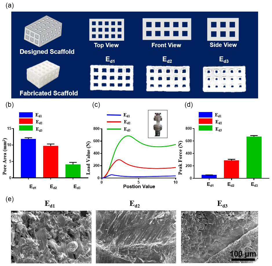
Figure 9Characterization of three types of PCL scaffolds with different SLS parameters. (a) Photograph of SLS-fabricated PCL scaffolds, (b) pore area, (c) stress–strain curves, (d) maximum compressive strength, and (e) cross-sectional SEM images of scaffolds.
3.5 Relationship between processing parameters and scaffold performance
To further study the relationship between scaffold performance and SLS process parameters and to verify the accuracy of the above simulation, bone tissue scaffolds with different energy densities were fabricated. Figure 9 shows the model picture of the scaffolds and actual images of the scaffolds with different energy densities. The influence of SLS process parameters on the performance of scaffolds is discussed for the following three aspects: pore size, mechanical properties, and microstructure.
3.5.1 Relationship between pore size and SLS parameters
From Fig. 9a, it is easy to notice the difference in the pore size of the bone tissue scaffolds with different energy densities. We measured the pore area of the bone tissue scaffold in the horizontal direction, and the results are shown in Fig. 9b. When the energy density is 0.089 J mm−3 (Ed1), the measured pore area is approximately 11.88 mm2. The energy density was increased to 0.178 J mm−3 (Ed2), and the pore area was reduced to 9.74 mm2. When the energy density is increased to 0.267 J mm−3 (Ed3), the original design pore of 9 mm2 is reduced to 4.09 mm2. The results show that, as the laser energy density increases, the pore size of the scaffold continues to decrease because the increase in energy density leads to the expansion of the molten-pool volume.
3.5.2 Relationship between mechanical strength and SLS parameters
Sufficient mechanical strength is essential for an ideal scaffold design. The stress–strain curves and compression strength with different energy densities are shown in Fig. 9c and d. First, all of the stress–strain curves show the same tendency. Furthermore, the results indicate that the mechanical properties can be improved from 53.4 to 671.1 N by increasing the energy density from 0.089 to 0.267 J mm−3. The enhancement of the mechanical strength was mainly due to the significant reduction in the pore size. Additionally, an increase in energy density will lead to denser connections between adjacent layers, which ultimately enhances the mechanical strength.
3.5.3 Relationship between micro-structure and SLS parameters
The mechanical properties of scaffolds can be explained by observing their microstructure. Hence, the SEM images of the scaffolds with different energy densities are shown in Fig. 9e. At the energy density of Ed1, several PCL particles remained in their virgin shape, and a large area of hollows was observed. When the energy density increased to Ed2, the temperature field of the powder was elevated, the PCL macromolecular chains became more active, and the microstructure became denser, resulting in the disappearance of hollows. When the energy density finally increased to Ed3, the microstructure became compact and dense.
Quantitative mutual verification analysis of the simulation and experiment reveals molten-pool geometry to be the dominant factor governing scaffold performance evolution. As illustrated in Fig. 7c, when the energy density increased from Ed1 (0.089 J mm−3) to Ed3 (0.267 J mm−3), the peak volumetric expansion rate of the molten pool reached 183 % (increasing from 2.7 × 10⁻⁴ to 7.6 × 10⁻³). This volumetric expansion significantly enhanced the melt interaction within the overlap regions of adjacent scanning tracks, leading to a marked improvement in the powder fusion completeness. This phenomenon was experimentally manifested as a sharp reduction in the scaffold pore area from 11.88 mm3 (Ed1) to 4.09 mm3 (Ed3), representing a reduction of 65.6 % (Fig. 9b).
Concurrently, the increase in the molten-pool depth directly strengthened the interlayer bonding strength. The simulation results (Fig. 6c) revealed that the molten-pool depth under Ed3 reached 162 µm, exceeding the single-layer powder thickness (150 µm) and inducing partial remelting of the underlying powder layer. This depth value represented a 65.3 % increase compared to that of Ed1 (98 µm). This increase is highly consistent with the experimental observation of the compressive strength surging from 53.4 N (Ed1) to 671.1 N (Ed3), as shown in Fig. 9d. This strong correlation validates the core mechanism whereby deep melting effectively eliminates weak interfaces by expanding the area of metallurgical bonding between layers.
Notably, the synergistic effect of the Marangoni flow and viscoelasticity optimized the morphology of the molten pool. As shown in Fig. 8a, the surface tension with a positive temperature coefficient ( > 0) drove the melt flow from the edges towards the center. Concurrently, the viscoelastic resistance (λ = 0.12 N mK−1), predicted by the Oldroyd-B model, reduced the average flow velocity in the Y direction to 34 % of that observed in pure metallic pools. The coupling of these two effects resulted in an increased molten-pool aspect ratio of 1.38 under Ed3 conditions. This “deep and narrow” morphology simultaneously promoted interlayer penetration (enhancing strength) and suppressed lateral melt overflow (reducing porosity). Ultimately, this translated into a dense, defect-free microstructure, as observed via scanning electron microscopy (Fig. 9e).
This study establishes a novel multiphysics model integrating Marangoni convection and viscoelastic effects to resolve molten-pool dynamics in polycaprolactone scaffold selective laser sintering. The key innovations and scientific contributions are summarized as follows: (1) the development of a validated volumetric heat source model incorporating powder thermophysical properties and boundary conditions (conduction, radiation, and convection), which accurately captures laser–powder interactions; (2) the mechanistic revelation that increasing energy density (Ed) elevates the melt pool temperature and/or volume while Marangoni–viscoelastic coupling induces a critical morphological transition to shorter and/or deeper pools, explaining defect formation at high Ed; (3) the quantitative establishment of Ed-dependent scaffold performance, where rising Ed reduces pore size, enhances mechanical strength, and densifies microstructure through controlled crystallization; and (4) the provision of physics-based process guidelines for pore geometry control and biomechanical property optimization, advancing precision manufacturing of biomedical implants.
In this study, we clarified the process–molten-pool–scaffold performance correlation and facilitated the effective production of bone scaffolds. However, the two-dimensional model used in this study has certain limitations. First, the two-dimensional model typically treats the powder bed as an equivalent continuous medium, making it difficult to precisely simulate the melting, the spherification of individual powder particles, and the microscopic three-dimensional details of the interactions between the particles. Second, the two-dimensional model cannot directly simulate the impact of complex scanning-path strategies on the molten pool. In the future, a three-dimensional finite-element model will be established to address these limitations.
The data sets used in this manuscript are available upon request.
YZ conceived the ideas and directed the work. JW designed the study. JH participated in the preparation and characterization of the PCL. JW performed the simulations and experiments. JW wrote the paper. FX was involved in the discussion of the results.
The contact author has declared that none of the authors has any competing interests.
Publisher's note: Copernicus Publications remains neutral with regard to jurisdictional claims made in the text, published maps, institutional affiliations, or any other geographical representation in this paper. While Copernicus Publications makes every effort to include appropriate place names, the final responsibility lies with the authors. Views expressed in the text are those of the authors and do not necessarily reflect the views of the publisher.
This work was financially supported by the National Natural Science Foun dation of China (grant no. U1632274, awarded to Junfeng Wang) and the Ministry of Science and Technology of China (grant no. 2016YFA0400901, awarded to Junfeng Wang). A portion of this work was supported by the High Magnetic Field Laboratory of Anhui Province.
This research has been supported by the National Natural Science Foundation of China (grant no. U1632274).
This paper was edited by Zhengjian Wang and reviewed by Atilla Savaş and two anonymous referees.
Castillo Sánchez, H. A., Jovanović, M. R., Kumar, S., Morozov, A., Shankar, V., Subramanian, G., and Wilson, H. J.: Understanding viscoelastic flow instabilities: Oldroyd-B and beyond,J. Non-Newton.Fluid Mech.,302,104742, https://doi.org/10.1016/j.jnnfm.2022.104742, 2022.
Chen, C. H., Shyu, V. B. H., Chen, J. P., and Lee, M. Y.: Selective laser sintered poly-ε-caprolactone scaffold hybridized with collagen hydrogel for cartilage tissue engineering, Biofabrication, 6, https://doi.org/10.1088/1758-5082/6/1/015004, 2014.
Cuadrado, A., Yánez, A., Martel, O., Deviaene, S., and Monopoli, D.: Influence of load orientation and of types of loads on the mechanical properties of porous Ti6Al4V biomaterials, Mater. Des., 135, 309–318, https://doi.org/10.1016/j.matdes.2017.09.045, 2017.
Du, Y., Liu, H., Yang, Q., Wang, S., Wang, J., Ma, J., Noh, I., Mikos, A. G., and Zhang, S.: Selective laser sintering scaffold with hierarchical architecture and gradient composition for osteochondral repair in rabbits, Biomaterials, 137, 37–48, https://doi.org/10.1016/j.biomaterials.2017.05.021, 2017.
Fu, Q., Saiz, E., Rahaman, M. N., and Tomsia, A. P.: Toward strong and tough glass and ceramic scaffolds for bone repair, Adv. Funct. Mater., 23, 5461–5476, https://doi.org/10.1002/adfm.201301121, 2013.
Hu, Y., Wang, J., Li, X., Hu, X., Zhou, W., Dong, X., Wang, C., Yang, Z., and Binks, B. P.: Facile preparation of bioactive nanoparticle/poly(ε-caprolactone) hierarchical porous scaffolds via 3D printing of high internal phase Pickering emulsions, J. Colloid Interface Sci., 545, 104–115, https://doi.org/10.1016/j.jcis.2019.03.024, 2019.
Hua, S., Su, J., Deng, Z., Wu, J., Cheng, L., and Yuan, X.: Microstructures and properties of 45S5 bioglass® & BCP bioceramic scaffolds fabricated by digital light processing, Addit. Manuf., 45, https://doi.org/10.1016/j.addma.2021.102074, 2021.
Huang, C., Qian, X., and Yang, R.: Thermal conductivity of polymers and polymer nanocomposites, Materials Science and Engineering, R Reports, 132, 1–22, https://doi.org/10.1016/j.mser, 2018.
Koons, G. L., Diba, M., and Mikos, A. G.: Materials design for bone-tissue engineering, Nat. Rev. Mater., https://doi.org/10.1038/s41578-020-0204-2, 2020.
Li, K., Zhou, H., Zhao, Z., Zhou, H, Yin, J., and Jin, J.: A study on transient molten pool dynamics in laser polishing of Ti6Al4V using numerical simulation, J. Manuf. Process., 65, 478–490, https://doi.org/10.1016/j.jmapro.2021.03.045, 2021.
Li, R., Liu, J., Shi, Y., Du, M., and Xie, Z.: 316L stainless steel with gradient porosity fabricated by selective laser melting, J. Mater. Eng. Perform., 19, 666–671, https://doi.org/10.1007/s11665-009-9535-2, 2010.
Ma, L., Wang, X., Zhao, N., Zhu, Y., Qiu, Z., Li, Q., Zhou, Y., Lin, Z., Li, X., Zeng, X., Xia, H., Zhong, S., Zhang, Y., Wang, Y., and Mao, C.: Integrating 3D Printing and Biomimetic Mineralization for Personalized Enhanced Osteogenesis, Angiogenesis, and Osteointegration, ACS Appl. Mater. Interfaces, 10, 42146–42154, https://doi.org/10.1021/acsami.8b17495, 2018.
Nandi, S. K., Kumar, R., and Agrawal, A.: Computationally inexpensive semi-analytical thermal model to predict melt-pool dimensions for a single-track in Selective Laser Melting,J. Manuf. Process.,80,469-479, https://doi.org/10.1016/j.jmapro.2022.06.025, 2022.
Partee, B., Hollister, S. J., and Das, S.: Selective Laser Sintering Process Optimization for Layered Manufacturing of CAPA 6501 Polycaprolactone Bone Tissue Engineering Scaffolds, J. Manuf. Sci. Eng. Trans. ASME., 128, 531–540, https://doi.org/10.1115/1.2162589, 2006.
Rajzer, I., Kurowska, A., Jabłoński, A., Jatteau, S., Śliwka, M., Ziąbka, M., and Menaszek, E.: Layered gelatin/PLLA scaffolds fabricated by electrospinning and 3D printing- for nasal cartilages and subchondral bone reconstruction, Mater. Des., 155, 297–306, https://doi.org/10.1016/j.matdes.2018.06.012, 2018.
Stuckensen, K., Schwab, A., Knauer, M., Muiños-López, E., Ehlicke, F., Reboredo, J., and Groll, J.: Tissue Mimicry in Morphology and Composition Promotes Hierarchical Matrix Remodeling of Invading Stem Cells in Osteochondral and Meniscus Scaffolds, Adv. Mater., 30, 1706754, https://doi.org/10.1002/adma.201706754, 2018.
Sun, S., Fei, G., Wang, X., Xie, M., Guo, Q., Fu, D., Wang, Z., Wang, H., Luo, G., and Xia, H.: Covalent adaptable networks of polydimethylsiloxane elastomer for selective laser sintering 3D printing, Chem. Eng. J., 412, https://doi.org/10.1016/j.cej.2021.128675, 2021.
Tolochko, N. K. , Arshinov, M. K., Gusarov, A. V., Titov, V. I., Laoui, T., and Froyen, L.: Mechanisms of selective laser sintering and heat transfer in Ti powder, Rapid Prototyp. J., 9, 314–326, https://doi.org/10.1108/13552540310502211, 2003.
Tortorici, M., Gayer, C., Torchio, A., Cho, S., Schleifenbaum, J. H., and Petersen, A.: Inner Strut Morphology Is the Key Parameter in Producing Highly Porous and Mechanically Stable Poly(ε-Caprolactone) Scaffolds via Selective Laser Sintering, Mater. Sci. Eng. C, 123, 111986, https://doi.org/10.1016/j.msec.2021.111986, 2021.
Williams, J. M., Adewunmi, A., Schek, R. M., Flanagan, C. L., Krebsbach, P. H., Feinberg, S. E., Hollister, S. J., and Das, S.: Bone Tissue Engineering Using Polycaprolactone Scaffolds Fabricated via Selective Laser Sintering, Biomaterials, 26, 4817–4827, https://doi.org/10.1016/j.biomaterials.2004.11.057, 2005.
Wu, Y. C., San, C. H., Chang, C. H., Lin, H. J., Marwan, R., Baba, S., and Hwang, W. S.: Numerical modeling of melt-pool behavior in selective laser melting with random powder distribution and experimental validation, J. Mater. Process. Technol., 254, 72–78, https://doi.org/10.1016/j.jmatprotec.2017.11.032, 2018.
Yang, J., Han, J., Yu, H., Yin, J., Gao, M., Wang, Z., and Zeng, X.: Role of molten pool mode on formability, microstructure and mechanical properties of selective laser melted Ti-6Al-4V alloy, Mater. Des., 110, 558–570, https://doi.org/10.1016/j.matdes.2016.08.036, 2016.
Yang, Y., Chu, L., Yang, S., Zhang, H., Qin, L., Guillaume, O., Eglin, D., Richards, R. G., and Tang, T.: Dual-functional 3D-printed composite scaffold for inhibiting bacterial infection and promoting bone regeneration in infected bone defect models, Acta Biomater., 79, 265–275, https://doi.org/10.1016/j.actbio.2018.08.015, 2018. .
Zhang, Y., Wang, C., Fu, L., Ye, S., Wang, M., and Zhou, Y.: Fabrication and Application of Novel Porous Scaffold in Situ-Loaded Graphene Oxide and Osteogenic Peptide by Cryogenic 3D Printing for Repairing Critical-Sized Bone Defect, Molecules., 24, 1669, https://doi.org/10.3390/molecules24091669, 2019.
Zhuravlev, E., Schmelzer, J. W. P., Wunderlich, B., and Schick C.: Kinetics of nucleation and crystallization in poly (ε-caprolactone) (PCL), Polymer., 52, 1983–1997, https://doi.org/10.1016/j.polymer, 2011.