the Creative Commons Attribution 4.0 License.
the Creative Commons Attribution 4.0 License.
 | 20 Mar 2026
Design, optimization, and testing of multifunctional interfaces for reconfigurable modular spacecraft
Shuangqing Yu
Qifeng Jiang
Xuanchen Ou
Jiawei Pi
Yuxiao Zhang
Yan Yang
Reconfigurable modular spacecraft (RMS) integrate reconfigurable characteristics with a modular architecture, which can be decomposed into several standardized and intelligent functional units. Each unit integrates the required subsystems and realizes interconnection through a universal interface. This study conducts an in-depth investigation on the core components of reconfigurable modular spacecraft units and multifunctional interface mechanisms. First, the structural design of the unit enclosure and interface mechanism is completed, covering the unit baseplate, frame, and key components that enable mechanical docking and power transmission. Second, systematic research is carried out on the motion trajectory optimization and profile design of the key components of this mechanism so as to achieve targeted error suppression and compliant docking. Based on the contact-impact theory and ADAMS dynamic modeling method, a dynamic model of the unit docking interface is established, and the feasibility of mechanical connection and power connection is verified. Furthermore, the follower motion laws affecting the connection accuracy are simulated and analyzed, which confirms the effectiveness of the selected optimal motion law. Finally, through docking tests, mechanical property tests, high- to low-temperature resistance tests, and signal transmission tests, the reliability of the proposed multifunctional interface operating in extreme environments is verified.
- Article
(4835 KB) - Full-text XML
- BibTeX
- EndNote


With the rapid advancement of space exploration technologies, aerospace missions have imposed increasingly high requirements on the functional scale and structural complexity of spacecraft systems (Arzo et al., 2022; Zhao et al., 2023b; Xue et al., 2021; Liu et al., 2022), and the application of large-scale spacecraft has further raised the comprehensive design requirements for spacecraft. However, constrained by the fairing envelope dimensions of launch vehicles, launch costs, and payload transport capacity, modern advanced spacecraft design faces a sharp contradiction between the large-scale demand and limited launch vehicle capacity (Liu et al., 2025; Gralla, 2006; Zhao et al., 2023a, 2025). Additionally, traditional spacecraft design typically adheres to a customized paradigm of a single platform matching a specific payload (Wang et al., 2023; Kief et al., 2019). This rigid architecture lacks flexibility and struggles to adapt to increasingly complex and variable on-orbit services and multi-mission collaborative requirements.
In view of this, the concept of RMS – integrating modular design with on-orbit reconfiguration technology – has emerged and has become a research hotspot in the current aerospace engineering field (Hu et al., 2023; Liu et al., 2024b; Dorsey and Watson, 2016; Nair et al., 2025). This technology decouples complex spacecraft systems into several standardized modular units with independent functions (e.g., power modules, propulsion modules, attitude and orbit control modules, communication modules, and payload modules), enabling physical connection and functional integration among modules via standardized interfaces. Such an architecture allows the spacecraft to flexibly reconfigure its configuration and instantaneously extend its functions on-orbit according to specific mission requirements, thereby significantly enhancing the system's mission adaptability and life-cycle cost-effectiveness (Piskorz and Jones, 2018; Cheung and Glass, 2025; Boesso and Francesconi, 2013).
Early-stage research in this field was represented by DARPA’s System F6 program (O'Neill et al., 2010), which sought to construct a decentralized, cluster-style “virtual satellite” via wireless inter-satellite links. Although this program validated the inherent survivability advantages of this architecture, it was ultimately terminated due to critical technical bottlenecks in wireless power transfer efficiency and high-dynamic guidance, navigation, and control (GNC) technologies. Subsequently, the research focus shifted to rigid-connection-based building-block architectures: DLR's iBOSS project (Kortman et al., 2015; Kortmann et al., 2017; Jankovic et al., 2018) proposed a standard grid-based design framework, whose core component, the intelligent Space System Interface (iSSI), achieved the integrated coupling of mechanical, electrical, thermal, and data subsystems; DARPA's Phoenix (Barnhart et al., 2013) and HISat projects (Melroy et al., 2015) further verified the feasibility of on-orbit aggregation of universal units. In recent years, with advancements in on-orbit servicing technology, robot-assisted assembly has emerged as a new trend. The European Union's MOSAR project (Letier et al., 2019) demonstrated the concept of module reconfiguration using walking robotic arms, while NASA's OSAM (Arney et al., 2021) series projects tackled key technologies such as autonomous docking based on visual servoing. Overall, reconfigurable modular spacecraft are currently in a critical window, transitioning from technology validation to engineering application. This development aligns with the broader pursuit of functional adaptability via structural morphing in various reconfigurable robotic systems (Wang et al., 2026).
Regarding modular spacecraft systems, extremely stringent requirements are placed on the guiding capability, fault tolerance, and reliability of interfaces during repeated insertion and extraction. If interface mechanisms experience wear or jamming after multiple reconfigurations, the entire assembly mission could be disrupted (Shoer and Peck, 2009). The multifunctional interface serves as the hub for physical connection, energy transfer, and information interaction between modules, and its performance directly determines the system’s reconfiguration efficiency and structural stiffness (Zhang et al., 2023). Based on functional composition, modular interfaces can typically be categorized into mechanical interfaces, power interfaces, thermal control interfaces, and data communication interfaces. Among these, the mechanical interface, as the carrier for other functional interfaces, undertakes load transmission, connection locking, and precision positioning between modules, forming the physical foundation for system integration (Liu et al., 2024a).
To address the aforementioned limitations, the compact coupled cylindrical cam mechanism has emerged as a key solution (Li et al., 2020). The iSSI interface, developed by the German Aerospace Center DLR Space Administration, is a prototypical example of this type of mechanism, which utilizes a rotating cam ring to drive locking elements, balancing high-stiffness connection with a compact form factor. The iSSI adopts an androgyny design, which means there is no distinction between the active and passive ends, and the structures of both ends are the same (Schervan et al., 2021; Kortmann et al., 2014, 2018). This not only reduces manufacturing complexity but also enables blind docking and interchangeability between arbitrary modules, significantly enhancing the system’s reconfiguration efficiency and fault tolerance.
Despite their notable configurational advantages, the dynamic performance of cylindrical cam mechanisms is highly dependent on the geometric design of the cam profile (Angeles and López-Cajún, 2012; Hsieh, 2014; Sun et al., 2018). If the pressure angle or motion law is improperly planned, the mechanism is prone to entering a jamming state or experiencing self-locking failure during reconfiguration. Therefore, how to optimize the profile design to balance motion smoothness and locking reliability is a core scientific issue that urgently needs to be addressed for the transition of such interfaces from principle validation to engineering application.
Thus, designing an optimal cam curve that satisfies both mechanical load-bearing requirements and motion smoothness remains a key challenge in the development of this type of interface. Against the application background of spacecraft modularity, this paper designs an efficient and reliable mechanical docking structure. It focuses on the design and optimization of the critical cylindrical cam mechanism, conducts dynamic simulation analysis of the interface device using ADAMS software, and performs experimental verification. The specific organization of this paper is as follows. Section 2 introduces the design parameters of the reconfigurable modular unit and its mechanical interface. Section 3 details the design of the cylindrical cam mechanism for the interface device, analyzes and optimizes the follower motion law, and proposes a more suitable motion law. Section 4 uses ADAMS software to simulate and analyze the dynamic characteristics of the interface device, obtaining its feasibility and parameters such as follower displacement, velocity, and acceleration. Section 5 describes ground tests on the reconfigurable modular unit and interface prototype, including the design of a control system for motor motion control. A series of tests – such as high- to low-temperature tests, tension–compression–bending–torsion strength tests, and docking tolerance tests – were conducted to validate the reliability of the proposed interface and unit.
Within the context of fully modular reconfigurable spacecraft, there are two methods of reconfiguration, as show in Fig. 1. The first method realizes the autonomous assembly of modular satellites by virtue of their own propulsion systems, thereby completing the reconfiguration of the spacecraft (Hu et al., 2023; Ye et al., 2024). The second method involves designing a more autonomous robotic arm on the satellite itself (Hamill et al., 2016; Collins and Shen, 2017). This robotic arm is equipped with multifunctional interfaces, identical to those on the modules, at both ends. Through these interfaces, the robotic arm can move around on the satellite and transport other modules. The application scenarios are described below. (1) A robotic arm equipped with multifunctional interfaces can reach every unit of the satellite system. (2) A robotic arm equipped with multifunctional interfaces can remove faulty or replaceable units. (3) When a satellite needs to remove an enclosed unit, the robotic arm needs to connect the dispersed satellite components to prevent them from drifting into other locations in space.
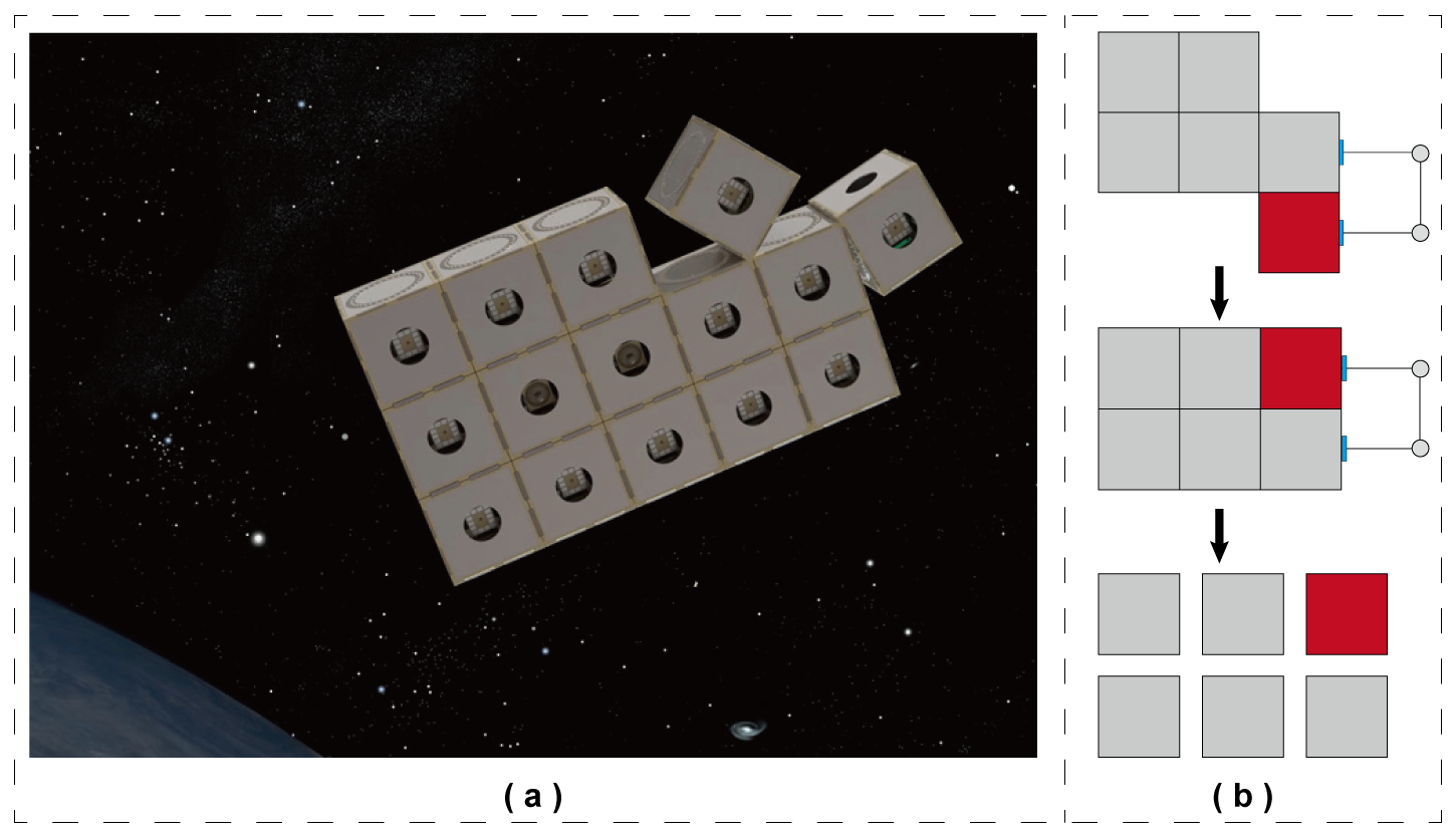
Figure 1Schematic diagram of the RMS: (a) concept of the HISat project by DARPA and (b) schematic of the deformation process of the RMS.
The design of RMS units must guarantee the stable operation of all internally integrated subsystem components in any space environment. Furthermore, these units must be capable of interconnecting via multifunctional interfaces to form a fully functional spacecraft system. As a critical component of the entire system, interfaces enable on-orbit services to be conducted as planned. Beyond transmitting mechanical loads, they are also responsible for transferring electrical power, data, and thermal energy between connected units, as shown in Fig. 2a.
The unit enclosure is based on a cubic structure, composed of components such as corner brackets, longitudinal beams, top panels, sandwich panels, and locking plates, as illustrated in Fig. 2b. The frame, which serves as the primary load-bearing structure of the enclosure, is formed by connecting 12 longitudinal beams with 8 corner brackets. The deformation and fracture characteristics of this frame directly determine the enclosure's performance, making its design paramount. The baseplate, which acts as the mounting platform for subsystem components, is assembled from the top and sandwich panels. All subsystem components are mounted onto the sandwich panel. For baseplates requiring interface installation, through-holes are machined into both the top and the sandwich panels. The locking plate is the key connecting mechanism between the interface assembly and the baseplate.
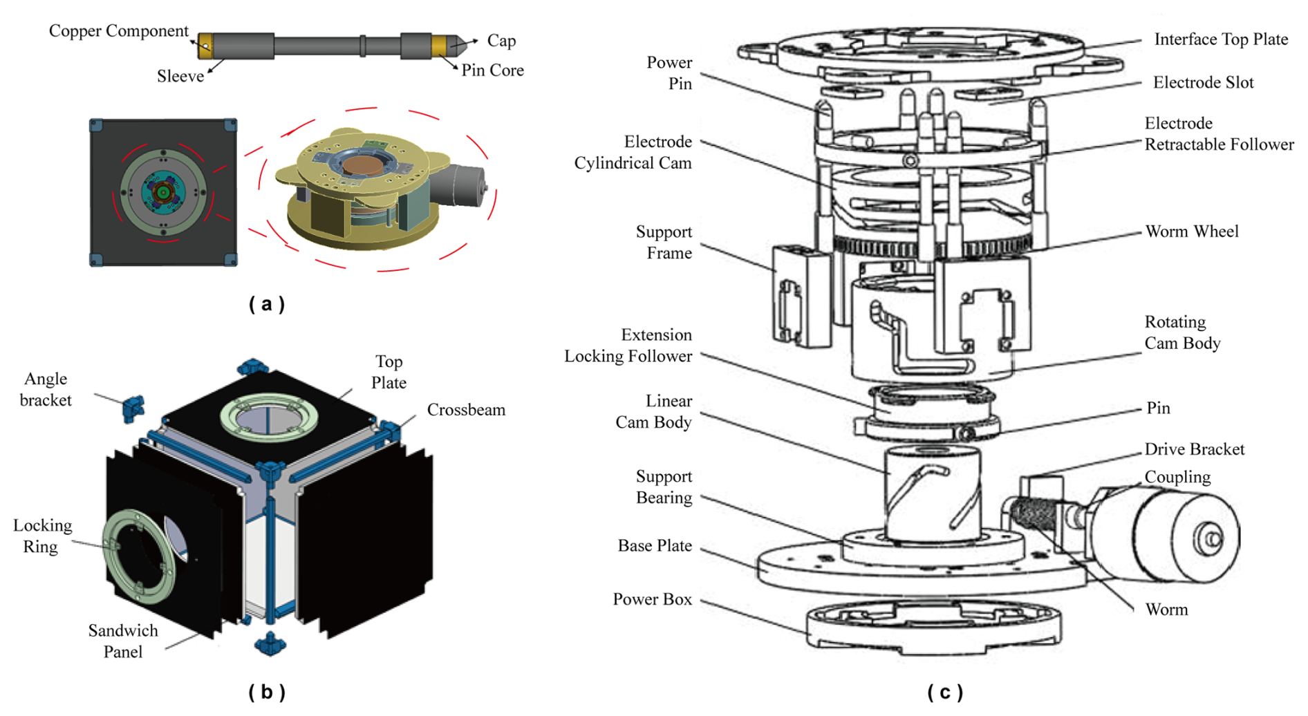
Figure 2Overview of reconfigurable module unit and its interface. (a) Design of cube module unit and its interface. (b) Exploded view of reconfigurable module unit. (c) Exploded view of docking interface.
The multifunctional interface, as illustrated in Fig. 2c, adopts an androgynous design. This design is intended to minimize reconfiguration obstacles between modular units and enhance docking efficiency. The docking process of the interface consists of three core actions: extension, retraction, and rotation, which are jointly accomplished by the drive mechanism and the telescopic mechanism. The drive mechanism employs a brushless DC gear motor, whose excellent load characteristics ensure efficient and stable power output. To alter the torque transmission direction and improve transmission efficiency, the system is equipped with a worm gear mechanism. This mechanism can achieve self-locking when the interface is stationary, thereby effectively enhancing the operational safety of the system.
On the top plate of the interface, power pins and electrode sockets are designed. The power pins are fixed on the electrode telescopic driven component, using the rotational motion of the cylindrical cam body to move the electrode telescopic driven component upward, allowing the power pins to extend out of the top plate and be inserted into the electrode sockets of the adjacent interface. This process forms an electrical circuit, ensuring stable power supply to the system. Additionally, when the power pins are inserted into the electrode sockets, they also serve an auxiliary positioning function, ensuring precise alignment of the interface during docking. This design not only enhances the reliability of the connection but also optimizes the efficiency of power supply, providing crucial support for the normal operation of the system.
As illustrated in Fig. 2a, the power pin primarily consists of four components: the core, the top cap, the sleeve, and the copper component.
The specific details are as follows:
-
Pin core. The pin core is fabricated from copper alloy.
-
Top cap. The top cap is made of polymer material and bonded to the tip of the core; its conical shape functions as a guiding element.
-
Sleeve. A polymer sleeve surrounds the exterior of the core to provide electrical insulation.
-
Copper component. A copper part is connected to the core, serving as the electrical contact for the lower region.
The telescopic mechanism consists of three cylindrical cam bodies and two driven components. Through meticulously designed curves for each phase of “ascent, pause, descent, and pause”, precise displacement control is realized. During the composite motion, the synchronous movement of multiple cylindrical cam bodies is crucial, requiring strict control of the motion sequence of each cam to avoid interference and ensure smooth and reliable docking of the interface. This series of precise coordination and control constitutes the complete process of interface docking, ensuring the efficient realization of its functions.
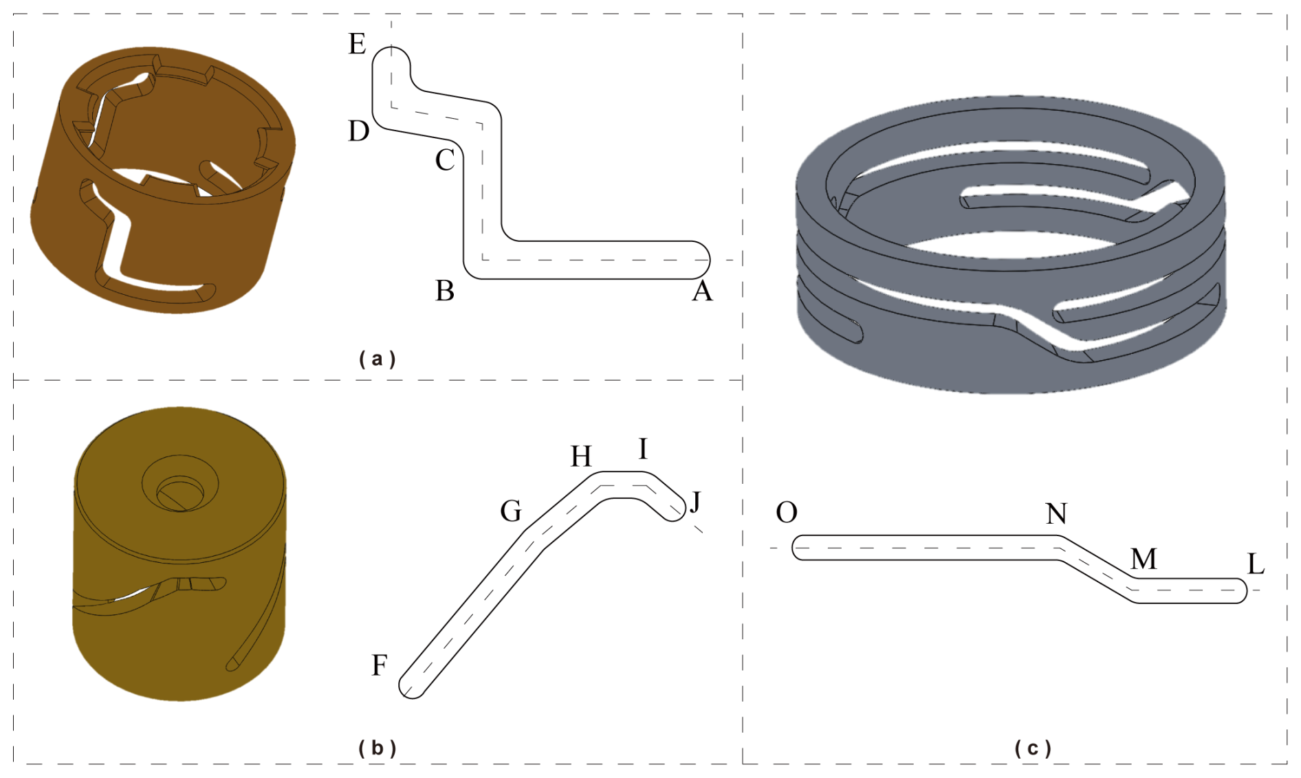
Figure 3Schematic of cam body model and its contour trajectory: (a) rotating cam body, (b) linear cam body, and (c) electrode cylindrical cam body.
The mechanical actuation mechanism of this interface comprises three cylindrical cam bodies and two followers: the rotating cam, the linear cam, and the electrode cylindrical cam, along with the extending locking follower and the electrode extension follower. The linear cam functions as a stationary guide, remaining static throughout the docking process. The rotating cam interacts with the linear cam and the extending locking follower via pin connections, where the profiles of the two cams jointly constrain the motion trajectory of the locking follower. The electrode cylindrical cam is rigidly fastened to the rotating cam using screws to ensure synchronous rotation; this cam is designed to control the extension of the electrode. During the docking process, the electrode cylindrical cam and the rotating cam operate as rotary cams revolving around the axis. They respectively drive the extending locking follower and the electrode extension follower to execute a compound motion consisting of rotation and linear ascent, thereby achieving the alignment and rigid connection of the interface.
The motion sequence and profile design of each cam body are illustrated in Fig. 3. The mechanical actuation relies on the coordination of three cams, with the rotating cam serving as the primary driver. Its motion profile is defined by four segments (AB → BC → CD → DE), as shown in Fig. 3a, which precisely govern the entire docking and locking process. Initially, in the horizontal segment AB, the rotating cam rotates to establish a 50° phase offset relative to the extending locking follower, during which the internal convex teeth at the top occupy a 30° sector, ensuring the follower is in a retracted and stable initial position ready for subsequent extension. Subsequently, in the vertical segment BC, as the follower ascends to point C, its tip reaches 3 mm above the top plate, initiating physical contact with the counterpart interface; simultaneously, the power pins begin extending at point B and achieve full extension at point C, establishing the initial electrical and energy transfer paths. Following this is the oblique segment CD, where the follower extends further outward past the top plate while maintaining a 20° phase offset, ensuring secure engagement with the counterpart's locking slots to prevent accidental disengagement during subsequent rotation. Finally, in the vertical segment DE, the follower completes its extension before retracting 1.2 mm to engage the locking mechanism, resulting in a clamping compression of 0.2 mm that ensures a rigid and reliable mechanical connection between the modules.
Acting as a stationary guide, the linear cam cooperates with the rotating cam to position the follower. Its profile comprises four segments (FG → GH → HI → IJ), shown in Fig. 3b, which are strictly synchronized with the rotating cam to precisely control the follower's trajectory. Segment FG corresponds to segment BC, matching its rotation angle and lift height to drive the outward extension of the follower and ensure alignment with the counterpart's interface. Segment GH, corresponding to segment CE, ensures the requisite 20° phase offset while maintaining the lift height of segment CD, keeping the follower securely engaged. Segment HI acts as a holding phase corresponding to DE, maintaining the follower at its maximum extension position of Point H to enable synchronous rotation of the two modules. The sequence concludes with segment IJ, where the follower executes the 1.2 mm linear retraction to finalize the clamping action, achieving the 0.2 mm compression for a tight mechanical lock.
The electrode cylindrical cam, which is rigidly fixed to the rotating cam, drives the vertical reciprocation of the power pins. Its profile consists of three segments (LM → MN → NO) as shown in Fig. 3c, synchronized with the rotating cam to ensure the power pins are extended at the correct moment. Segment LM corresponds to segment AB of the rotating cam, functioning as a dwell phase where the follower height remains constant, keeping the power pins retracted to avoid interference during the initial phase offset. During segment MN corresponding to BC, the cam rotates 30° to drive the electrode extension follower upward by 8 mm, ensuring the power pins are fully extended to establish reliable electrical and energy connections. The final segment, NO, holds the follower at this maximum height; to ensure reliability, the angular span of segment NO is designed to be greater than the sum of segments CD and DE, yet within the maximum allocatable angle under uniform-distribution conditions, maintaining the power pins in an extended state throughout the entire docking and locking process.
The power interface is composed of electrode slots and power pins. The power pins are arranged in four pairs, with each pair containing one positive and one negative pole; this configuration satisfies the requirements for a hermaphroditic design. These pins are mounted on the electrode extension follower, which is equipped with three guide rollers. To minimize friction against the cam profile grooves during movement, micro-bearings are installed on the heads of these rollers. During the docking process, the coil springs within the electrode slots of the passive interface connect with those in the active interface via the copper cores of the power pins, thereby facilitating electrical signal transmission between the two interfaces.
This section systematically completes the detailed structural design of the modular unit and its interface system. Serving as the critical link between the unit enclosure and the spacecraft baseplate, the interface mechanism functions not merely as a physical carrier for mechanical attachment, but also as the core executive actuator for facilitating spacecraft modular assembly and on-orbit topological reconfiguration. Crucially, it effectively guarantees connection reliability and positional precision of the module under complex mechanical environments. Centered on this objective, the specific design work is elaborated across three dimensions: first, the unit enclosure design, which balances protection capabilities with lightweight requirements; second, the mechanical interface structural design, aimed at achieving high-rigidity locking; and third, the power interface design, which satisfies the specific constraints of hermaphroditic geometry and floating contact. Collectively, these efforts establish a comprehensive and viable modular electromechanical connection scheme.
The cam mechanism within the interface structure comprises three cylindrical cam bodies and two followers, operating in a “two-moving, one-static” state. The transmission accuracy of this mechanism is primarily constrained by the geometric deviation of the cam profile grooves. To effectively mitigate these errors and enhance interface transmission accuracy, the design and optimization of follower motion laws have become a critical aspect of research and development. Although the constant-velocity linear motion law is structurally simple, abrupt changes in velocity and acceleration at the start and end points induce rigid and flexible impacts, severely compromising the mechanism's lifespan.
The performance evaluation of cam profile curves relies primarily on three key characteristic values of the follower: velocity, acceleration, and jerk. First, the maximum velocity (Vm) is positively correlated with the cam pressure angle; excessive velocity increases the pressure angle, thereby intensifying friction and wear while reducing transmission efficiency. Second, the maximum acceleration (Am) is proportional to the inertial force; excessive acceleration triggers severe vibration, degrading motion accuracy. Finally, the maximum jerk (Jm) reflects the intensity of motion impact and is directly correlated with the fatigue life of the profile surface. Theoretically, the design should aim to minimize Vm, Am, and Jm. However, significant nonlinear coupling and mutual constraints exist among these three parameters. Consequently, the design of the follower motion law is essentially a typical multi-objective optimization problem. To address this, this study constructs a mathematical model with Vm, Am, and Jm as sub-objective functions. By adopting an appropriate weighting strategy, the problem is transformed into a single-objective optimization task to achieve the comprehensive optimum of the mechanism's dynamic performance.
Given that the follower motion in the interface operates under low-speed and light-load conditions, the applicable motion laws for the cylindrical cam mechanism primarily include polynomial types and trigonometric function types. We adopt a combined motion law strategy, which takes the linear polynomial motion law as the core basis and introduces quadratic polynomial or simple harmonic motion laws for transition and modification. This design constitutes a necessary technical approach to address the rigid–flexible impact issue of cylindrical cam mechanisms under low-speed and light-load conditions, as well as to ensure transmission accuracy and service life.
Both the harmonic-modified constant-velocity motion law and the quadratic-modified constant-velocity motion law effectively suppress rigid and flexible impacts while balancing the complexity of the cylindrical cam profile design with its manufacturability. Accordingly, this study selects these two combined motion laws as the subjects for optimization. The optimization objective is defined as follows: given the cam rise angle, determine the optimal cam rotation angle parameters through optimization calculations to minimize dynamic characteristic values such as velocity, acceleration, and jerk.
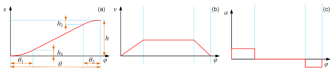
Figure 4Curve diagram of constant-velocity motion law with quadratic term correction: (a) displacement, (b) velocity, and (c) acceleration.
The quadratic-modified constant-velocity motion law is formed by combining the linear polynomial motion law with the quadratic polynomial motion law, as shown in Fig. 4 During the rise phase, the motion profile consists of a constant-acceleration segment, a constant-velocity segment, and a constant-deceleration segment.
Here s is displacement; v is velocity; a is acceleration; J is jerk; θ is the total rise angle; θ1 and θ2 are the cam angles for the acceleration and deceleration phases of the rise, respectively; h is the total rise lift; h1 and h2 are the lifts for the acceleration and deceleration phases, respectively; and ϕ is the cam rotation angle. To ensure that the displacement curve is continuously differentiable and the velocity curve is free of discontinuities, θ1, θ2, h1, and h2 must satisfy the following conditions:
Subsequently, optimization principles are applied to determine the optimal positions of the transition points – specifically the values of h1, h2, θ1, h2, θ1, and θ2. The optimization objective is to minimize the Vm, Am, and Jm values of the cam mechanism. Accordingly, the objective evaluation function is established as follows:
where the weighting factor ω must satisfy the normalization, specifically
Due to the differing dimensions of the sub-objective functions, a unified objective function cannot accurately reflect their relative importance. Consequently, it is necessary to perform non-dimensionalization on the dimensional sub-objective functions to derive the functions fi(x). Let
To reduce the design complexity of the cylindrical cam profile groove while satisfying design requirements, this study adopts a symmetrical structure; i.e., θ1=θ2. Based on this approach, the sub-objective functions Vm Am and Jm are reformulated as , , and , respectively, yielding
When ,
When ,
The equations are non-dimensionalized to yield
Assuming each weighting factor is set as , Eq. (3) can be rewritten as
The constraints are given as follows:
In the MATLAB Optimization Toolbox, the solution obtained is as follows:
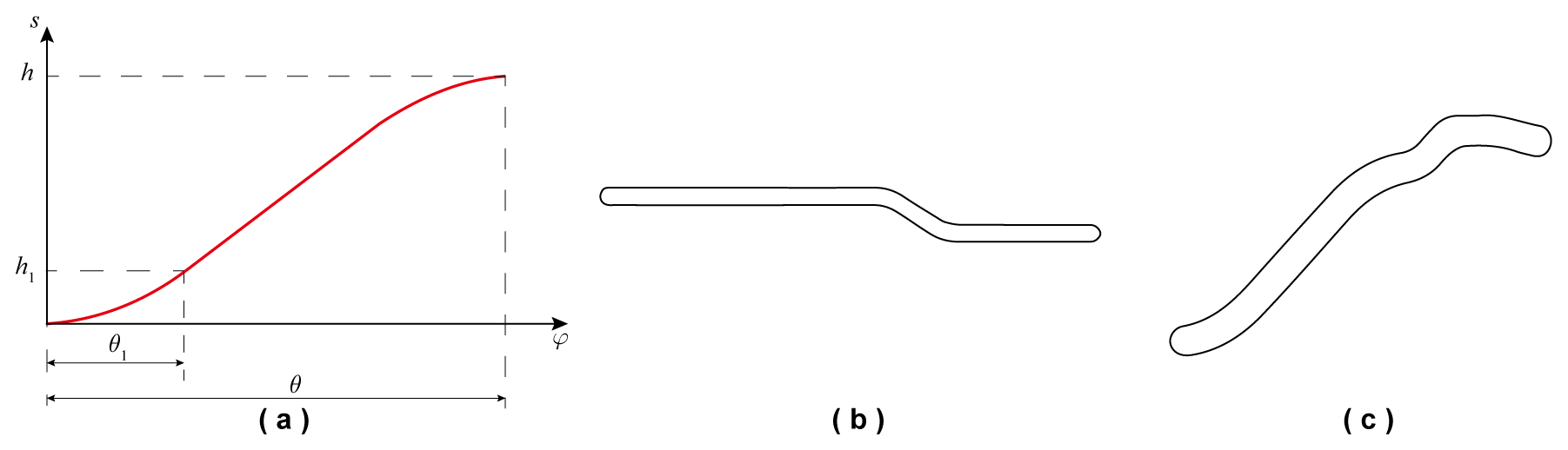
Figure 5Cam optimization design: (a) schematic of optimized displacement curve, (b) curved groove of electrode cylindrical cam, and (c) curved groove of linear cam.
During the connection process, the electrode cylindrical cam rotates through a total angle of 180. Its groove profile is divided into three segments designed according to different kinematic laws. The first segment is designed based on the relationship between rotation angle and displacement. The second segment is designed using the selected optimized quadratic-modified uniform-velocity motion law. The third segment employs the same design method as the first segment. In the second curved groove segment, the electrode cylindrical cam has a rise angle of θ=30° and a rise distance of h=8 mm. Substituting these parameters into Eq. (12) yields θ1=8.8° and h1=1.7mm. Based on the displacement equation of the quadratic-modified uniform-velocity motion law, the optimized displacement curve can be obtained, and a schematic illustration is shown in Fig. 5b. Substituting these values into the displacement curve and selecting a roller radius r=2 mm as specified by the design requirements, the optimized working contour of the electrode cylindrical cam can be plotted.
The linear cam follower is likewise designed using the optimized quadratic-modified uniform-velocity motion law. For the first curved groove segment, the rise angle is θ=70° and the rise distance is h=19 mm. Substituting these parameters into Eq. (12) yields θ1=20.5° and h1=3.9mm. The calculation method for the remaining curved groove segments is identical to that described above. Following these steps sequentially to solve and plot the profile, the working contour of the linear cam can be obtained, as shown in Fig. 5c.
During both positioning and rigid-connection phases, contact collisions arise between rigid components, exemplified by interactions such as those between power supply pins and electrode slots, as well as between rollers and cam profile grooves. These collisions are transient in duration and involve substantial contact forces, which exhibit pronounced nonlinear behavior (Zhao et al., 2021). Consequently, determining the collision force constitutes a nontrivial computational challenge. Two principal approaches are commonly employed: the impact function method and the restitution method. Due to the difficulty in accurately configuring the associated parameters in the restitution method, the impact function method is adopted herein for collision force computation. In the impact function method, the contact force between two components is evaluated via an impact function, which comprises two constituents: an elastic force and a damping force. The damping component originates from the relative velocity between the two bodies, whereas the elastic component results from their mutual penetration. The general form of the impact function is expressed as follows:
In the expression, k denotes the stiffness coefficient; q0 represents the initial distance between the two colliding parts; q is the actual distance during the collision process; e stands for the impact exponent; c indicates the damping coefficient; and d refers to the penetration depth, also known as the interference distance.
To avoid discontinuity in the damping force during the collision process, a step function is introduced in the expression. Its general form and computational expression are given as follows:
where and .
The accuracy of the contact force model established through the impact function is significantly influenced by parameter settings. In collision contact force simulations, the parameters that need to be determined include the stiffness coefficient k, the impact exponent e, the damping coefficient c, and the penetration depth d.
For collisions between rotating objects, the stiffness coefficient can be approximately determined according to the following expression:
where the equivalent radius R and the equivalent elastic modulus E* can be obtained from the following equations:
where R1 and R2 are the radii of the two colliding objects at the point of collision, v1 and v2 are Poisson's ratios of the two objects, and E1 and E2 are the elastic moduli of the two objects.
The friction force induced by contact slip can be calculated using the equation below:
where Ffriction is the friction force, and μ is the friction coefficient.
The impact exponent e reflects the degree of nonlinearity in the material behavior. The value of the impact exponent is taken as 1.5 for metal-to-metal contacts and 2 for rubber-like materials. During the collision process, energy dissipation is represented by the damping coefficient c, whose value typically ranges from 0.1 % to 1 % of the stiffness coefficient. In this section, c is taken as 100 N (m s−1)−1. At the instant of initial contact between the objects, no damping force is present. As the interference distance increases, the damping force grows accordingly until it reaches its maximum value. The interference distance at which the maximum damping force occurs is defined as the penetration depth d, which is typically set to 0.1 mm.
The docking between modules is initially accomplished by a robotic arm that establishes preliminary contact and positioning between the active and passive modules. In the presence of positional misalignment between the two modules, the conical holes on the cover of the active power pins and the tapered openings of the passive electrode slots compensate for the initial docking deviation. Under the control of the robotic arm, corrections in pitch, yaw, and roll directions are performed, thereby relaxing the required operational precision of the robotic system. After eliminating the initial positional deviation between the modules, the interface drive motor continues to operate, driving the cam mechanism to rotate and complete the rigid connection between the interfaces.
In the simulation of the interface process, contact collision settings are configured according to the parameters established in the preceding section. The electrode cylindrical cam and the rotating cam rotate synchronously. During the positioning and rigid-connection phases, the electrode cylindrical cam rotates 180°, causing the electrode telescoping follower to ascend 8 mm in the vertical direction. Simultaneously, the rotating cam rotates 180°, driving the extension-engaging follower to rotate 110° and rise 21.8 mm vertically.
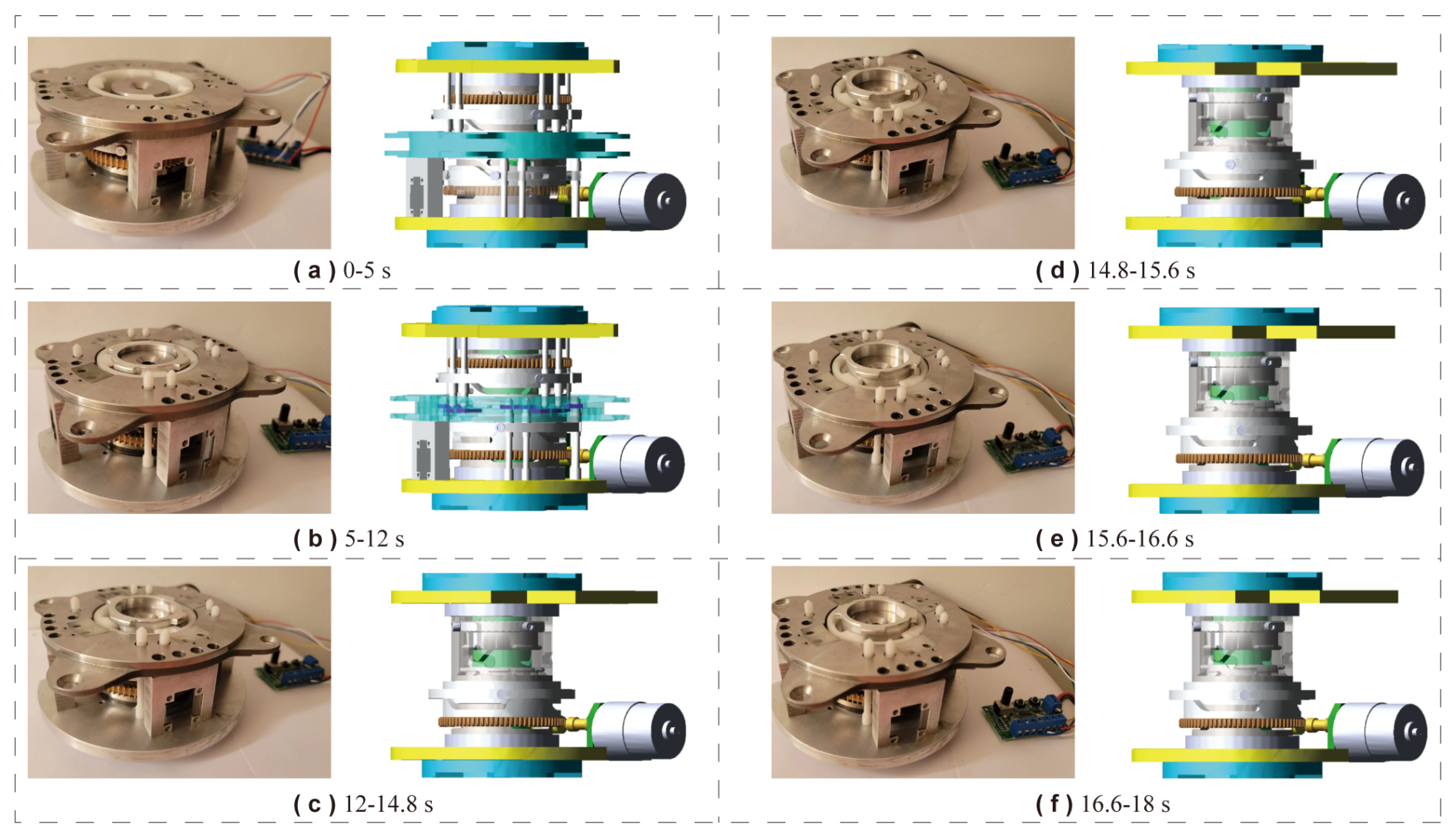
The interface connection process consists of six sequential stages. The first stage (0–5 s) is the initial alignment phase. As shown in Fig. 6a, the passive interface remains stationary while the rotating cam on the active interface rotates 50° under drive actuation. Both the extension-engagement follower and the electrode telescopic follower remain stationary, resulting in a 50° angular offset between the rotating cam and the extension-engagement follower. The second stage (5–12 s) involves positioning and initial insertion, as shown in Fig. 6b. Between 5 and 8 s, the electrode cylindrical cam drives the electrode telescopic follower upward by 8 mm to its highest position, enabling the power pins to engage the electrode slots and complete electrical alignment. Thereafter, the power pins remain fixed at this elevated position. From 5 to 12 s, the rotating cam rotates an additional 70°, causing the extension-engagement follower to rotate 70° and rise approximately 19 mm vertically, positioning it about 3 mm above the top plate. It should be noted that minor deviations in the actual vertical travel of the extension-engagement follower from the designed value of 19 mm occur due to slight geometric alterations in the cam groove profile resulting from file format conversion during model import; however, these deviations remain within acceptable limits. The third stage (12–14.8 s) corresponds to pre-locking preparation, as shown in Fig. 6c. During this phase, the power pins remain stationary, and for clarity of visualization, non-moving components are hidden in the figure. The rotating cam rotates 28°, driving the extension-engagement follower to rotate 8° and creating a 20° angular offset relative to the cam, while the follower ascends a further 2 mm vertically. The fourth stage (14.8–15.6 s) is the locking ascent phase, as shown in Fig. 6d. The rotating cam and the extension-engagement follower rotate synchronously by 8°, and the locking blade rises with the follower by about 2 mm to its highest position. The fifth stage (15.6–16.6 s) is the locking hold phase, as shown in Fig. 6e, during which the rotating cam and the follower rotate together by 10°, with the follower maintaining its maximum vertical height. The sixth and final stage (16.6–18 s) is the final compression phase, as shown in Fig. 6f. Here, the rotating cam and the follower rotate together by 14°, while the follower descends approximately 1.2 mm vertically. This downward movement presses the active locking blade firmly against the passive locking blade, thereby completing the rigid locking connection between the active and passive interfaces. The resulting displacement curves of the extension follower and the electrode telescopic follower obtained from the simulation are shown in Fig. 7, respectively.
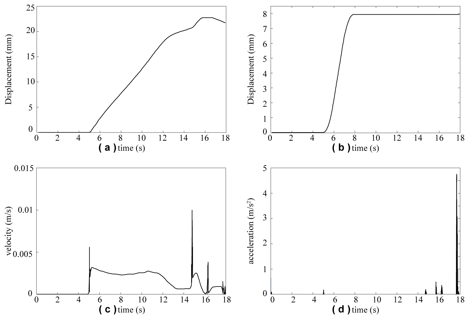
Figure 7Motion curves of key interface components: (a) Centroid displacement curve of extending and screwing follower, (b) centroid displacement curve of electrode telescopic follower, (c) velocity curve of extending and screwing follower, and (d) acceleration curve of extending and screwing follower.
Figure 7c and d show the velocity curve and acceleration curve of the extension-engaging follower, respectively. It can be seen from the simulation results that the follower exhibits slight velocity fluctuations during operation, with a maximum velocity of approximately 0.01 m s−1 and a peak acceleration of around 4.58 m s−2. The occurrence of the aforementioned velocity and acceleration fluctuations stems from the reserved fit clearance between the cam curve groove and the follower roller. From the quantitative data of velocity fluctuation amplitude and peak acceleration, the magnitude of such fluctuations is extremely small, which fully satisfies the design requirements for the mechanism's motion stability and low-impact performance.
For the electrode cylindrical cam mechanism, dynamic simulations were conducted using the optimized constant-velocity motion law with quadratic modification and the optimized constant-velocity motion law with simple harmonic modification, respectively, to determine the contact collision forces between the roller and the cam groove profile along the X, Y, and Z directions. Figure 8a–c show the collision forces under the optimized quadratic-modified constant-velocity motion law, while Fig. 8d–f present the results under the optimized simple harmonic-modified constant-velocity motion law. The simulation results indicate that, under the optimized quadratic-modified constant-velocity motion law, the maximum contact collision forces between the roller and the groove in the X, Y, and Z directions are 4.3, 12.5, and 55° N, respectively. To further evaluate the influence of the motion law on contact performance, a comparative analysis was performed using the optimized simple harmonic-modified constant-velocity motion law. The results show that the corresponding maximum collision forces in the X, Y, and Z directions are 5.5, 16.2, and 87° N, respectively.
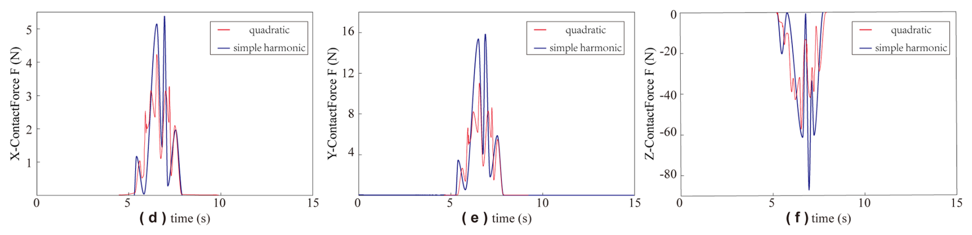
Figure 8Collision force of roller: (a) collision force of roller in X direction, (b) collision force of roller in Y direction, and (c) collision force of roller in Z direction.
A comparative analysis of the peak collision forces corresponding to the two optimized motion laws demonstrates that the quadratic-modified law achieves lower peak forces across all three directional degrees of freedom. The magnitude of the peak collision force directly characterizes the intensity of impact loads and inertial effects acting between the cam groove and the roller. Lower peak values correspond to mitigated impact and inertial forces, which are conducive to minimizing contact wear and prolonging the service life of the mechanism. Therefore, in terms of reducing contact collision forces and suppressing mechanism wear, the optimized quadratic-modified constant-velocity motion law presents more excellent dynamic performance.
Table 1Collision force peak values between roller and curve groove.
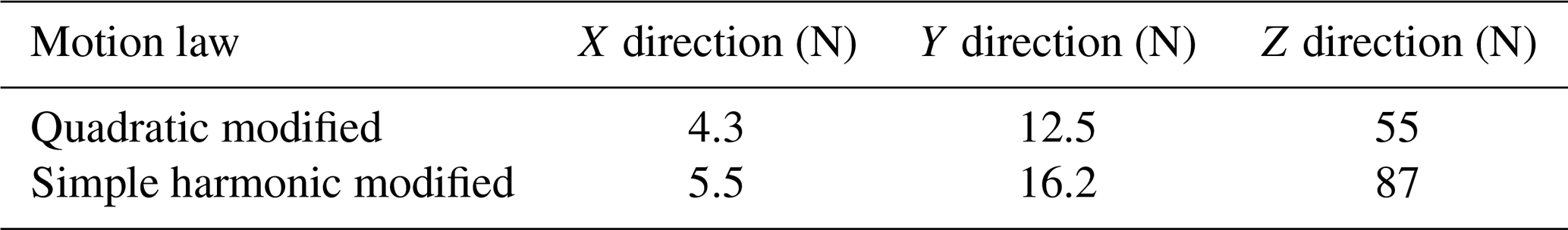
The peak collision forces between the roller and the cam curve groove in the X, Y, and Z directions are summarized in Table 1. As indicated in the table, when the optimized quadratic-modified constant-velocity motion law is employed, the peak collision forces in all three directions are consistently lower than those obtained with the optimized simple harmonic-modified constant-velocity motion law. Lower collision forces contribute to reduced wear between the cam groove and the follower, thereby minimizing transmission errors in the interface. These results validate the appropriateness of the selected motion law for the follower mechanism.
To systematically evaluate the assembly smoothness and operational reliability of the proposed integrated interface, this study conducted dedicated validation experiments to assess its working capability under realistic operating conditions. A 6-degree-of-freedom industrial robotic arm was employed as the actuation mechanism, coupled with a purpose-built docking module to replicate the structural engagement and loading scenarios encountered in actual application environments. The progression of the experiment is clearly illustrated in Fig. 9a. In the tests, a payload of 4.8 kg was applied to examine the interface’s mechanical stability and deformation control under load-bearing conditions. The interface bodies were rigidly mounted on both the docking module and the end-effector flange of the robotic arm, thereby ensuring repeatable installation accuracy in spatial pose.
A hierarchical positioning strategy was adopted for alignment. Initially, coarse positioning was performed using the machine vision system integrated with the robotic arm; image recognition and feature-matching algorithms were utilized to extract the spatial coordinates of target markers, generating preliminary alignment commands. Subsequently, the process transitioned to a tolerance-based autonomous docking mode intrinsic to the interface design, which guarantees accurate connection even when positional deviations lie within a prescribed tolerance envelope. This two-stage approach effectively mitigates the influence of initial pose errors on docking success rate and enhances the system robustness against variations in illumination or partial occlusions.
The overall docking procedure was designed to evaluate, in a single integrated test sequence, three critical performance metrics: docking tolerance – the ability to achieve reliable connection within permissible deviations in position and orientation, encompassing the combined allowance for translational and angular misalignments; docking time – the total duration from completion of visual coarse positioning to establishment of a rigid lock via interface engagement, reflecting the system’s dynamic response and operational efficiency; and load capacity – the maximum load threshold at which the interface maintains structural integrity and functional operability under sustained loading conditions. Through these multidimensional assessments, the interface's comprehensive performance can be fully characterized in terms of kinematic compatibility, dynamic matching, and long-term service reliability.
To comprehensively evaluate the structural load-bearing performance of the designed interface, systematic mechanical property tests were conducted to characterize its tensile and compressive capabilities. High-precision mechanical testing equipment was employed to apply controlled axial tensile and compressive loads, thereby obtaining deformation and failure characteristics under ultimate loading conditions.
In the tensile performance test, a monotonically increasing tensile force was applied along the interface's connection axis at a constant loading rate until the preset limit of 6000 N was reached, as shown in Fig. 9b-I. Throughout the loading process, no significant plastic deformation, displacement loosening, or structural failure was observed, indicating that the interface maintained good geometric stability and connection stiffness under high-tensile loading. This ultimate tensile load substantially exceeds the expected docking load range for most on-orbit assembly missions, thereby verifying – from a static load standpoint – the interface's reliability for aerospace reconfigurable satellite applications.
In the compressive performance test, an incremental loading scheme was similarly adopted to apply axial compressive force, progressively increasing it to a limit of 400 N, as shown in Fig. 9b-I. Experimental results showed that at this pressure threshold the interface retained its complete geometric form and mechanical continuity, exhibiting no visible crushing, microcracking, or fracture. These observations demonstrate excellent compressive load-bearing characteristics and resistance to localized instability. Together, the bidirectional tensile and compressive tests constitute a complete static load-capacity assessment framework, quantitatively revealing the safety margin and structural robustness of the interface under typical aerospace loading conditions and providing direct mechanical evidence for its practical deployment.
To further investigate the interface’s service performance in extreme thermal environments representative of space, high- and low-temperature operational adaptability tests were carried out. The environmental temperature was set within a range of −50 to +70 °C. Each test cycle comprised low- and high-temperature phases, each lasting 3 h, with a 0.5 h thermal soak at the target temperature prior to interface activation and execution of a full docking sequence. Specifically, the procedure began with a 0.5 h soak at −50 °C, followed by interface activation and one autonomous docking; this sequence was repeated three times. The environment was then switched to +70 °C, and the same soak-and-dock procedure was repeated three additional times. The experimental setup is shown in Fig. 9c, which documents the internal layout of the thermal chamber and the temperature settings.
Test results indicated that the interface successfully completed docking tasks at both −50 and +70 °C. No positioning inaccuracy, connection failure, or motion jamming attributable to thermal expansion and contraction of materials was observed, demonstrating favorable high- and low-temperature resistance and thermal stability. It can therefore be concluded that the interface remains fully functional within the typical orbital thermal environment of spacecraft, meeting the stringent requirement for wide-temperature-range adaptability of connecting components in aerospace reconfigurable platforms.
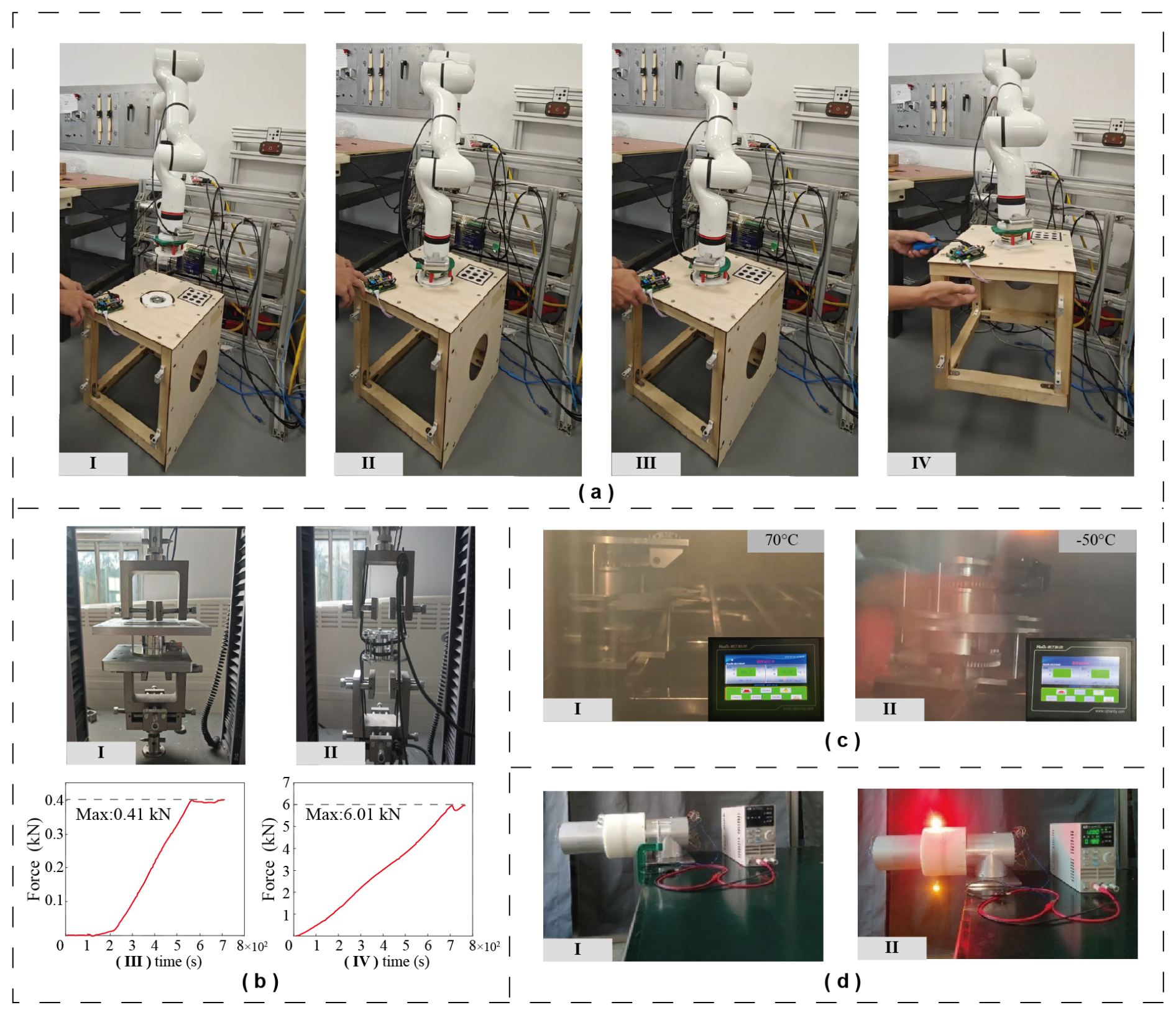
Figure 9Interface reliability tests: (a) robotic-arm-reconfigurable module docking test, (b) mechanical performance test, (c) high- to low-temperature docking test, and (d) interface signal transmission test.
To verify the functional completeness of the designed interface in terms of electrical and data signal transmission, a dedicated connectivity test was conducted, as shown in Fig. 9d. The test architecture employed a unilateral power supply and bilateral signal communication scheme: the active side of the interface was connected to a stable 12 V DC power source, while the passive side had no independent power unit and only retained signal reception and forwarding circuitry. This configuration simulated the asymmetric power supply conditions that may arise after modular satellites are docked in orbit. Upon completion of mechanical docking, the passive interface successfully received both electrical energy and modulated signals transmitted from the active interface, driving its onboard status indicator to illuminate. This visually confirmed the establishment of an electrical pathway. To quantitatively assess signal fidelity, a high-speed digital oscilloscope was used to synchronously capture the electrical waveforms at both the active and the passive ends. Comparative analysis revealed that the waveform captured at the passive end was identical to the output waveform from the active end in terms of amplitude, frequency, and pulse timing, with distortion levels below the resolution limit of the measuring instrument. This indicates that the interface maintains high signal integrity and low transmission loss during operation.
The test not only demonstrated the interface’s ability to provide reliable DC power transfer, but also verified its transparent transmission capability for digital and analog data signals. Specifically, without reliance on additional relay devices, a data link between modules could be established instantaneously upon docking. The excellent waveform consistency implies that the internal contact structures and signal channels possess superior electrical contact stability and interference immunity, enabling maintenance of communication quality under space–environment factors such as vibration, thermal variation, and microgravity.
Through systematic experimental validation, this section comprehensively evaluated the integrated interface’s performance in mechanical docking, static load bearing, extreme-temperature adaptation, and electrical/data transmission. Results show that the interface achieves high-precision, highly robust autonomous docking while retaining structural integrity and functional stability under tensile and compressive loads of 6000 and 400 N, respectively, with a significant safety margin. It operates reliably over a wide temperature range of −50 to +70 °C, exhibiting excellent thermal stability and resistance to environmental disturbances. Under unilateral power supply conditions, it enables low-loss, high-fidelity transmission of both electrical energy and data signals, ensuring instantaneous establishment of plug-and-play communication links concurrent with mechanical connection. These performance attributes confirm that the interface meets the high-reliability requirements of aerospace reconfigurable satellite applications in terms of kinematic compatibility, dynamic matching, thermal environmental adaptability, and electrical connectivity.
Modular units and interface devices, as core components of reconfigurable spacecraft, play an irreplaceable role in spacecraft assembly, reconfiguration, maintenance, and servicing – their performance directly governs mission flexibility and reliability. This paper presents a full-process investigation into modular units and interface devices, covering design, optimization, and verification. First, structural and functional designs were completed: the interface principle based on a composite cylindrical cam mechanism was detailed, and key components (e.g., power pins, motor slots) were integrated to enable mechanical locking and electrical signal transmission. Second, to mitigate transmission errors, the follower motion law was optimized by adopting the optimized quadratic-modified uniform-velocity motion law, which enhances transmission smoothness. Subsequently, dynamic analysis and experimental verification were conducted. The vertical lift distances of the locking-extending helical follower and the power-connecting electrode telescopic follower were measured to be 21.8 and 8 mm, respectively. Comparative simulations of the peak roller–groove collision forces under two distinct motion laws verified the rationality of the adopted motion law. Further verification via ADAMS software modeling and prototype tests confirmed the engineering feasibility of locking and power pin docking functions. Finally, a series of tests – including robotic arm docking, mechanical (tensile load: 6000 N; compressive load: 400 N), high- to low-temperature (−50 to +70 °C), and signal transmission tests – systematically verified the interface’s comprehensive reliability in rapid precise docking, extreme load/environmental adaptation, and low-loss high-fidelity electrical/data transmission.
This paper establishes a complete research paradigm for reconfigurable modular interfaces, from conceptual design to multi-condition experimental verification. Test results provide detailed data support for interface design, proving the feasibility of the proposed solution for aerospace reconfiguration tasks. The study not only constructs a theoretical method system for multi-condition performance verification but also forms a reproducible benchmark database at the experimental level, laying a solid foundation for modular connection technologies in complex missions (e.g., deep-space exploration, large-scale space platforms, on-orbit manufacturing). It holds significant engineering promotion value and scientific research significance.
All raw data can be provided by the corresponding author upon request.
SY, QF, and JL planned the campaign; SY, XO, and JP performed the measurements; SY analyzed the data and wrote the paper draft; and YZ and YY designed the figures.
At least one of the (co-)authors is a member of the editorial board of Mechanical Sciences. The peer-review process was guided by an independent editor, and the authors also have no other competing interests to declare.
Publisher's note: Copernicus Publications remains neutral with regard to jurisdictional claims made in the text, published maps, institutional affiliations, or any other geographical representation in this paper. The authors bear the ultimate responsibility for providing appropriate place names. Views expressed in the text are those of the authors and do not necessarily reflect the views of the publisher.
The authors thank the editors and reviewers for their efforts.
This work was supported in part by the National Key R&D Program of China (grant no. 2018YFB1304600), the CAS Interdisciplinary Innovation Team (grant no. JCTD-2018-11), and the National Natural Science Foundation of China (grant no. 51775541).
This paper was edited by Pengyuan Zhao and reviewed by two anonymous referees.
Angeles, J. and López-Cajún, C. S.: Optimization of cam mechanisms, Vol. 9, Springer Science & Business Media, https://www.semanticscholar.org/paper/Optimization-of-cam-mechanisms-Angeles-Lopez-Cajon/a042fdff2e895176dae2128ff5ac94610515c3d5 (last access: 16 March 2026), 2012. a
Arney, D., Sutherland, R., Mulvaney, J., Steinkoenig, D., Stockdale, C., and Farley, M.: On-orbit servicing, assembly, and manufacturing (OSAM) state of play, https://ntrs.nasa.gov/citations/20210022660 (last access: 16 March 2026), 2021. a
Arzo, S. T., Sikeridis, D., Devetsikiotis, M., Granelli, F., Fierro, R., Esmaeili, M., and Akhavan, Z.: Essential technologies and concepts for massive space exploration: Challenges and opportunities, IEEE T. Aero. Elec. Sys., 59, 3–29, 2022. a
Barnhart, D., Sullivan, B., Hunter, R., Bruhn, J., Fowler, E., Hoag, L. M., Chappie, S., Henshaw, G., Kelm, B. E., Kennedy, T., Mook, M., and Vincent, K.: Phoenix program status-2013, in: AIAA SPACE 2013 conference and exposition, p. 5341, https://doi.org/10.2514/6.2013-5341, 2013. a
Boesso, A. and Francesconi, A.: ARCADE small-scale docking mechanism for micro-satellites, Acta Astronaut., 86, 77–87, 2013. a
Cheung, K. and Glass, B.: Automated Reconfigurable Mission Adaptive Digital Assembly Systems (ARMADAS), in: Ames Partnerships Day, https://ntrs.nasa.gov/api/citations/20250002322/downloads/APD2025 ARMADAS.pdf (last access: 16 March 2026), 2025. a
Collins, T. J. and Shen, W.-M.: Integrated and adaptive locomotion and manipulation for self-reconfigurable robots, in: Conference Towards Autonomous Robotic Systems, pp. 150–165, Springer, https://link.springer.com/chapter/10.1007/978-3-319-64107-2_13 (last access: 16 March 2026), 2017. a
Dorsey, J. and Watson, J.: Space assembly of large structural system architectures (SALSSA), in: AIAA SPACE 2016, p. 5481, https://doi.org/10.2514/6.2016-5481, 2016. a
Gralla, E. L.: Strategies for launch and assembly of modular spacecraft, Ph.D. thesis, Massachusetts Institute of Technology, https://dspace.mit.edu/handle/1721.1/37886 (last access: 16 March 2026), 2006. a
Hamill, D., Bowman, L., Gilman, D. A., and Belvin, W. K.: High leverage technologies for in-space assembly of complex structures, in: AIAA SPACE 2016, p. 5397, https://doi.org/10.2514/6.2016-5397, 2016. a
Hsieh, J.-F.: Design and analysis of indexing cam mechanism with parallel axes, Mech. Mach. Theory, 81, 155–165, 2014. a
Hu, G., Li, Y., Li, X., Zhang, G., Zhang, Z., Wang, X., and Man, W.: Modular self-reconfigurable spacecraft: Development status, key technologies, and application prospect, Acta Astronaut., 207, 240–256, 2023. a, b
Jankovic, M., Brinkmann, W., Bartsch, S., Palazzetti, R., and Yan, X.: Concepts of active payload modules and end-effectors suitable for Standard Interface for Robotic Manipulation of Payloads in Future Space Missions (SIROM) interface, in: 2018 IEEE Aerospace Conference, pp. 1–15, IEEE, https://doi.org/10.1109/AERO.2018.8396406, 2018. a
Kief, C., Hannon, M., Lyke, J., Peters, C., Fronterhouse, D., and Ahlberg, M.: SPARC–1: a new, improved modular 6U spacecraft, in: 2019 IEEE Aerospace Conference, pp. 1–8, IEEE, https://doi.org/10.1109/AERO.2019.8742248, 2019. a
Kortman, M., Ruhl, S., Weise, J., Kreisel, J., Schervan, T., Schmidt, H., and Dafnis, A.: Building block based iBoss approach: fully modular systems with standard interface to enhance future satellites, in: 66th International Astronautical Congress (Jerusalem), vol. 2, https://www.semanticscholar.org/paper/Building-Block-Based-"iBOSS"-Approach:-Fully-with-Kortmann-Schervan/aca641e175a7d2d8960d1b76634a1aa5ebf10c63 (last access: 16 March 2026), 2015. a
Kortmann, M., Dafnis, A., and Reimerdes, H.: Development and breadboard testing of a mechanical coupling interface for modular spacecraft systems, in: European Conference on Spacecraft Structures, Materials & Environmental Testing, Braunschweig, Germany, pp. 01–04, https://www.semanticscholar.org/paper/Development-and-Breadboard-Testing-of-a-Mechanical (last access: 16 March 2026), 2014. a
Kortmann, M., Meinert, T., Dafnis, A., and Schroeder, K.: Multifunctional interface for modular satellite systems with robotic servicing capabilities, in: Proceedings of the 68th International Astronautical Congress, https://doi.org/10.1007/S42423-018-0009-1, 2017. a
Kortmann, M., Zeis, C., Meinert, T., Dueck, A., and Schroder, K.: Design and qualification of a multifunctional interface for modular satellite systems, in: Proceedings of the 69th International Astronautical Congress, Bremen, Germany, pp. 1–5, https://www.sla.rwth-aachen.de/cms/institut-fuer-strukturmechanik-und-leichtbau/Forschung/Publikationen/~faog/Details/?lidx=1&file=745832 (last access: 16 March 2026), 2018. a
Letier, P., Yan, X. T., Deremetz, M., Bianco, A., Grunwald, G., Roa, M., Krenn, R., Arancón, M. M., Dissaux, P., Casarrubios, J. S. G., RuizLucini, R., De Filippis, L., Porcelluzzi, G., Post, M., Walshe, M., and Perryman, P.: MOSAR: Modular spacecraft assembly and reconfiguration demonstrator, in: 15th symposium on advanced space technologies in robotics and automation, https://www.semanticscholar.org/paper/MOSAR:-Modular-spacecraft-assembly-and-demonstrator-Letier-Yan/56810c9b567649eaba7e9621be5ea4bc8fc69f8f (last access: 16 March 2026) 2019. a
Li, J.-H., Liu, Z.-J., Wang, D.-P., Tian, Y., and Zhao, Y.-C.: Fault mode analysis and reliability optimization design of a mechanical interface based on cylindrical cam mechanisms, Eksploatacja i Niezawodność, 22, 715–723, 2020. a
Liu, C., Luo, Y., Yue, X., and Li, S.: Hierarchical Cooperative Adaptive Model Predictive Control for Swarm Self-assembly of Large-scale Spacecraft, Aerospace Science and Technology, p. 111538, https://doi.org/10.1016/j.ast.2025.111538, 2025. a
Liu, J., Zhao, P., Wu, C., Chen, K., Ren, W., Liu, L., Tang, Y., Ji, C., and Sang, X.: SIASAIL-I solar sail: from system design to on-orbit demonstration mission, Acta Astronaut., 192, 133–142, 2022. a
Liu, S., Zhang, E., Xu, Z., and Zhang, J.: Design of Docking Interfaces for On-Orbit Assembly of Large Structures in Space, Sensors, 24, 6534, 2024a. a
Liu, T., Wang, Z., Zhang, Y., Wang, Z., Liu, Z., Zhang, Y., and Huang, P.: Self-reconfiguration Strategies for Space-distributed Spacecraft, in: 2024 IEEE/RSJ International Conference on Intelligent Robots and Systems (IROS), pp. 9879–9884, IEEE, https://doi.org/10.1109/IROS58592.2024.10802829, 2024b. a
Melroy, P., Hill, L., Fowler, E. E., Hunter, R., Eagen, J., Sullivan, B. R., Will, P., and Palmer, J.: DARPA phoenix satlets: Progress towards satellite cellularization, in: AIAA SPACE 2015 Conference and Exposition, p. 4487, https://doi.org/10.2514/6.2015-4487, 2015. a
Nair, M. H., Rai, M. C., Reade, S., Bloch, O., Adlen, S., Soltau, M., and Homfray, D. A.: In-orbit assembly of high-value modular infrastructures: Holistic analysis and mission concepts, Acta Astronaut., https://doi.org/10.1016/j.actaastro.2025.09.070, 2025. a
O'Neill, M., Yue, H., Nag, S., Grogan, P., and de Weck, O.: Comparing and optimizing the DARPA system F6 program value-centric design methodologies, in: AIAA SPACE 2010 Conference & Exposition, p. 8828, https://doi.org/10.2514/6.2010-8828, 2010. a
Piskorz, D. and Jones, K. L.: On-orbit assembly of space assets: A path to affordable and adaptable space infrastructure, The aerospace corporation, pp. 12–13, https://aerospace.org/sites/default/files/2018-05/OnOrbitAssembly_0.pdf (last access: 16 March 2026), 2018. a
Schervan, T., Kreisel, J., Schroeder, K., and Wingo, D. R.: New horizons for exploration via flexible concepts based on building blocks using the standardized issi (intelligent space system interface) modular coupling kit by iboss, in: Global Space Exploration Conference, pp. 14–18, https://doi.org/10.1109/IROS58592.2024.10802829, 2021. a
Shoer, J. P. and Peck, M. A.: Flux-pinned interfaces for the assembly, manipulation, and reconfiguration of modular space systems, The J. Astronaut. Sci., 57, 667–688, 2009. a
Sun, J., Liu, X., Yin, Z., Zeng, T., Su, T., Ding, X., and Shao, Y.: Optimisation design investigation of a cylindrical end curve towards a non-continuous profile of a cam mechanism, The J. Eng., 2018, 1753–1760, 2018. a
Wang, J., Tian, Y., Xi, F., Chablat, D., Ren, G., and Zhao, Y.: A Pill bug-inspired Two-mode Mobile Robot Covered with Sliding Curvy Shells, IEEE T. Robot., pp. 1–14, https://doi.org/10.1109/TRO.2026.3661723, 2026. a
Wang, X., Zhang, F., Hu, D., Chen, R., and Song, Z.: Review, Prospect and Technical Challenge of Launch Vehicle, in: Autonomous Trajectory Planning and Guidance Control for Launch Vehicles, pp. 1–31, Springer Nature Singapore Singapore, https://link.springer.com/chapter/10.1007/978-981-99-0613-0_1 (last access: 16 March 2026), 2023. a
Xue, Z., Liu, J., Wu, C., and Tong, Y.: Review of in-space assembly technologies, Chinese J. Aeronaut., 34, 21–47, 2021. a
Ye, D., Wang, B., Wu, L., Del Rio-Chanona, E. A., and Sun, Z.: PO-SRPP: A decentralized pivoting path planning method for self-reconfigurable satellites, IEEE T. Ind. Electron., 71, 14318–14327, 2024. a
Zhang, Z., Li, X., Li, Y., HU, G., Wang, X., Zhang, G., and TAO, H.: Modularity, reconfigurability, and autonomy for the future in spacecraft: A review, Chinese J. Aeronaut., 36, 282–315, 2023. a
Zhao, P., Liu, J., Li, Y., and Wu, C.: A spring-damping contact force model considering normal friction for impact analysis, Nonlinear Dynam., 105, 1437–1457, 2021. a
Zhao, P., Liu, J., Wu, C., Ye, S., Yang, Q., and Hao, G.: Deployment analysis of membranes with creases using a nonlinear torsion spring model, Int J. Mech. Sci., 255, 108444, https://doi.org/10.1016/j.ijmecsci.2023.108444, 2023a. a
Zhao, P., Wu, C., and Li, Y.: Design and application of solar sailing: A review on key technologies, Chinese J. Aeronaut., 36, 125–144, 2023b. a
Zhao, P., Liu, J., Wu, C., Zhao, Y., Yu, S., and Jing, X.: Theoretical modelling and sensitivity analysis for triangular membrane wrinkling of solar sail under muti-field effects, Appl. Math. Model., p. 116646, https://doi.org/10.1016/j.apm.2025.116646, 2025. a