the Creative Commons Attribution 4.0 License.
the Creative Commons Attribution 4.0 License.
 | 18 Mar 2026
A locking and unlocking mechanism integrating compliant and rigid structures for modular vehicles
He Gou
Xiaobiao Shan
Yan Wang
Xiaopeng Yang
Wupeng Liu
This paper presents the design of a novel rigid–compliant-integrated locking and unlocking mechanism tailored for applications such as modular vehicle systems, where automated connection, compactness, and high-stiffness locking are essential. The proposed approach combines rigid and compliant components: rigid elements handle high load-bearing and self-locking tasks, while compliant elements are used in low-load, planar-motion sections to reduce friction and wear, simplifying the design. A detailed mechanism configuration is introduced, along with dynamic modeling and simulation. Stress analysis confirms that the compliant parts remain within safe limits under significant deformation. A 3D-printed prototype was fabricated, and preliminary tests verify the feasibility of the design. By integrating the advantages of both rigid and compliant mechanisms, the system achieves simplicity, reliability, and compactness while enabling automated actuation via a motor. This work offers a reference for future designs of rigid–compliant-integrated systems and provides a new configuration concept for locking and unlocking mechanisms.
- Article
(5530 KB) - Full-text XML
- BibTeX
- EndNote


Modular vehicle design refers to the division of a vehicle into distinct functional modules, which can be assembled into a complete vehicle as needed (Luccarelli et al., 2015; Pandremenos et al., 2009; Saab et al., 2019). Compared to traditional design approaches, modularization enables parallel development of individual modules within a limited time frame, facilitating the generation of various vehicle configurations through modular recombination. This approach greatly enhances design flexibility and production efficiency, and it allows more diverse vehicle functions and appearances within the same R&D cycle (Bayrak et al., 2020; Lin et al., 2023). However, the implementation of such a modular vehicle architecture also faces several engineering challenges, one of which is the design of the locking and unlocking mechanism. To achieve efficient and rapid connection and disconnection between modules, it is necessary to develop a locking and unlocking device that provides reliable connection, features a compact structure, and can be actuated in an automated manner. Currently, locking and unlocking devices have been widely applied in aerospace systems (Choi et al., 2022; Li et al., 2025) and railway transportation (Cole and Sun, 2006; Jackiewicz, 2021; Wagner et al., 2021). However, existing mechanisms, though mature in these domains, show limitations when applied to modular vehicle systems. These include (1) incompatibility in actuation methods – most aerospace mechanisms are thermally actuated and incapable of re-engagement after release (Bian et al., 2020; Lee and Han, 2025; Yue et al., 2022) and (2) a lack of sufficient constraints – railway couplers are designed to allow lateral freedom between adjacent carriages to accommodate track curvature and typically provide only directional constraints, resulting in loose interconnections (Gao et al., 2017). Therefore, current solutions fall short in meeting the requirements of modular vehicle systems, which demand automation, full constraint, high stiffness, and strong locking force. Moreover, the spatial limitations within vehicle modules necessitate a compact design.
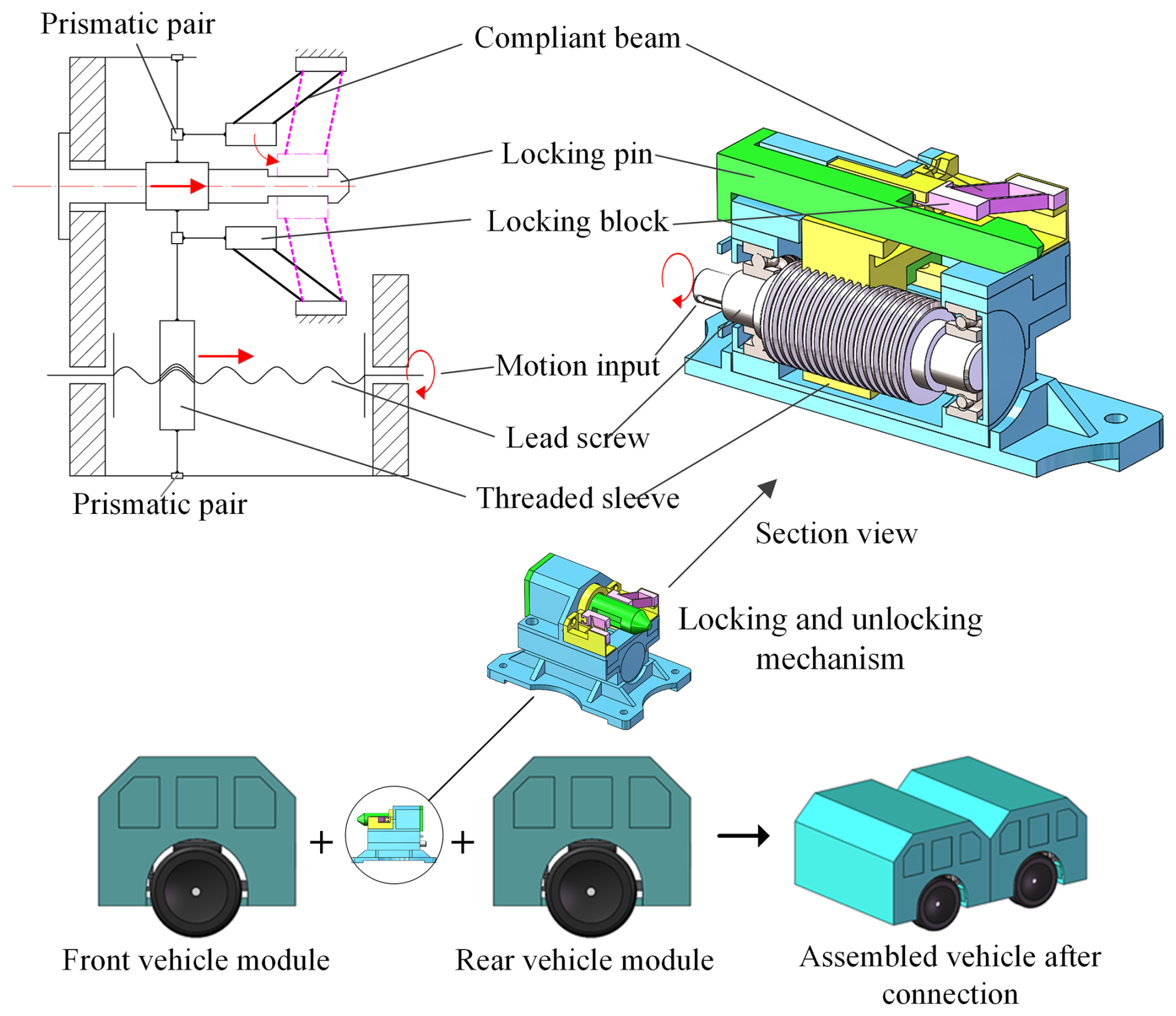
Figure 1Schematic diagram of the rigid–compliant-integrated locking and unlocking mechanism.
To meet these diverse design requirements, achieving efficient transmission with secure locking becomes essential. One promising approach is to utilize compliant mechanisms, which reduce the number of components while ensuring functional transmission. Unlike conventional rigid mechanisms that depend on rigid joints, compliant mechanisms achieve motion and force transmission through elastic deformation of the material itself (Howell, 2013). Due to the absence of mechanical joints, compliant mechanisms allow simplified, monolithic, and miniaturized designs (Baviskar et al., 2024; Culpepper and Anderson, 2004; Liao et al., 2025; Xiong et al., 2025) while also eliminating frictional wear (Ding et al., 2023; Samadikhoshkho et al., 2025). Nevertheless, compliant mechanisms introduce challenges in modeling and analysis due to the coupling between force and motion. This prevents motion analysis from being isolated from stress analysis (Rösner et al., 2015). For large-deformation-compliant mechanisms, nonlinearities further complicate modeling efforts (Henning et al., 2021).
In this paper, we propose a rigid–compliant-integrated locking and unlocking mechanism. The rigid component employs a screw–sleeve transmission mechanism to provide high reduction ratios and self-locking capability, while the compliant part utilizes a parallelogram-shaped compliant hinge to achieve planar motion transmission. Compared with conventional pin–slot structures, the use of compliant mechanisms simplifies the configuration and eliminates friction-induced wear.
The remainder of this paper is organized as follows: Sect. 2 introduces the novel rigid–compliant-integrated locking and unlocking mechanism. Section 3 presents modeling and simulation analysis of the mechanism. Section 4 details the fabrication of a 3D-printed prototype and validates its functional feasibility. Section 5 concludes the paper.
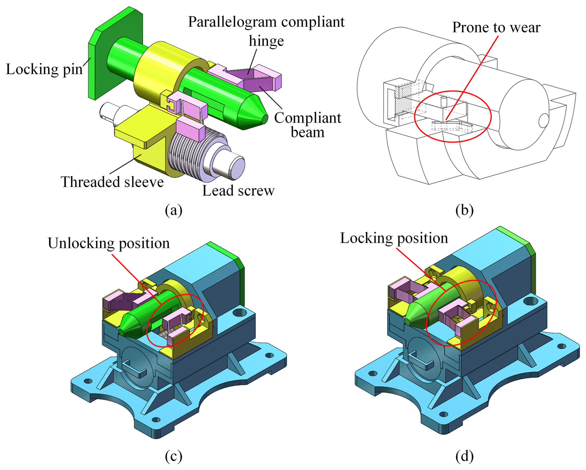
Figure 2Detailed design of the locking and unlocking mechanism. (a) Internal structure of the rigid–compliant-integrated locking and unlocking mechanism. (b) Transmission mechanism of the locking block using pin–slot pair. (c) Unlocked state. (d) Locked state.
The schematic diagram of the proposed locking and unlocking mechanism is shown in Fig. 1. The input motion is rotational, facilitating automated locking and unlocking through motor actuation. During operation, external torque is applied to the lead screw, which converts the rotational input into axial displacement of the threaded sleeve via screw transmission. The lead screw mechanism is chosen to achieve a high transmission ratio and self-locking capability. The threaded sleeve pushes the compliant hinge, causing deformation that drives the locking block into contact with the locking pin. Once contact is made, the mechanism enters the locking phase. Under the applied driving torque, the screw pair generates axial force, which is transmitted via the threaded sleeve to the locking block. The block then applies axial clamping force onto the locking pin – this force serves as the system's preload. The locking pin is connected to the mating module and is tightly secured under this preload force. By utilizing the nonlinear large deformation behavior of the compliant mechanism, the locking block can follow a predefined trajectory without the need for traditional guiding elements. This compliant-deformation-based approach eliminates frictional losses and assembly errors associated with traditional guidance mechanisms while also reducing structural complexity and manufacturing cost.
Following the schematic in Fig. 1, the full configuration of the proposed mechanism is illustrated in Fig. 2a. It consists of a rigid portion and a compliant portion. The rigid portion includes the lead screw and threaded sleeve. The end of the threaded sleeve is designed with dual rectangular slots to simultaneously transmit thrust and restrict parasitic rotation of the locking block. The compliant portion consists of two parallelogram-shaped compliant hinges working in parallel. In most previous studies, parasitic motion in parallelogram compliant hinges is minimized to preserve the motion accuracy of parallel mechanisms (Chen et al., 2024; Ni et al., 2010; Qiang and Wang, 2025). However, this work takes the opposite approach, intentionally leveraging the parasitic motion. When thrust is applied, the compliant hinge allows the locking block to move axially along the locking pin and laterally across it, thereby achieving a clamping and locking action. Figure 2b shows a conventional rigid mechanism employing a pin–slot structure. While this can also enable 2D transmission, it requires both a pin slider and a slot component. Moreover, the pin–slot joint is prone to wear and failure. The proposed compliant hinge design avoids these drawbacks. Figure 2c and d depict the unlocking and locking states of the hybrid mechanism, respectively. This design fully integrates the advantages of rigid and compliant mechanisms: rigid elements are used where high reduction ratio, self-locking, and load-bearing are required, while compliant hinges are employed in sections where load demand is lower but friction avoidance is critical. This results in a simple, compact, and efficient mechanical system.
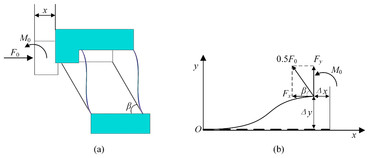
Figure 3Force diagram of the parallelogram compliant hinge. (a) Overall analysis of the compliant flexure hinge. (b) Force analysis of the compliant beam.
3.1 Modeling of the rigid subsystem
The Lagrangian method is employed to derive the dynamic model of the locking and unlocking mechanism. The general form of Lagrange's equation is
where is the Lagrangian function, defined as the difference between the system's kinetic energy T and potential energy V; qi is the generalized coordinate; and Qi is the generalized force.
The transmission mechanism has a single degree of freedom, so one generalized coordinate suffices. Let the rotation angle of the lead screw, θ1, be chosen as the generalized coordinate. The axial displacement of the threaded sleeve is
where P is the lead of the screw. The torque-induced torsional deformation angle Δθ1 is negligible during the transmission phase due to small applied loads.
In the locking phase, as axial clamping force increases, the threaded components experience noticeable elastic deformation, and Δθ1 must be considered. The velocity of the threaded sleeve is
where Js represents the rotational inertia of the screw and mn represents the mass of the threaded sleeve.
Setting the central axis plane of the lead screw as the zero potential energy plane, the gravitational potential energy is constant:
where hn represents the distance between the center of gravity of the threaded sleeve and the gravity reference plane.
The generalized force Qi is expressed as
In the equation, Fj and Mk represent the jth external force and the kth external moment in the system, while rj and θk are their corresponding position vectors. During the transmission process, the generalized forces acting on the transmission system mainly include the driving torque Ts of the lead screw, the friction force Ffn acting on the threaded sleeve, the friction force Ffb exerted by the locking block on the sleeve, and the reaction force F. Substituting these forces into Eq. (5), the expression of generalized force during the transmission process is obtained:
Since the forces acting on the device are relatively small during the transmission phase, the elastic deformation between components can be neglected, and the elastic potential energy of the system is VE=0. Substituting all expressions into Lagrange's equation yields the dynamic equation of the locking and unlocking mechanism during the transmission process:
Assuming the relationship between the thrust F0 applied to the compliant module and the axial displacement x satisfies the function F0=C(x), then Eq. (7) can be written as
At the beginning of the locking phase, the locking block is already in contact with the locking pin. Therefore, during the locking process, the threaded sleeve, locking block, and locking pin will undergo elastic deformation due to compression while moving axially. For elastic bodies, the actual force acting on the compressed object is the restoring force generated by its elastic deformation. Based on this, a combined force analysis of the threaded sleeve, locking block, and locking pin is carried out. The elastic deformations of the threaded sleeve, locking block, and locking pin during the locking process are defined as Δlg, Δlb, and Δln, respectively. The relationship between the deformations of each component and the displacement of the threaded sleeve's center of mass Δl during locking is
Within the elastic range, deformation of the components follows Hooke's law. According to Hooke's law, the axial clamping force acting on the locking pin during locking relates to the axial displacement of the threaded sleeve as follows:
where kn,kb, and kg are the equivalent stiffnesses of the screw pair, the locking block, and the locking pin, respectively, and kw is the total stiffness of the three components in series. Substituting Eq. (2) into Eq. (10), the expression for the clamping force F acting on the threaded sleeve during the locking process is obtained:
From Eq. (11), the expression for the torsional angle Δθ1 of the screw pair under torque during the locking process is derived:
By combining Eqs. (11) and (12), the relationship between the torsional angle Δθ1 and the rotation angle θ1 of the lead screw is obtained:
Based on the above calculation results, the expression for the elastic potential energy of the transmission system during the locking process is obtained:
Next, the generalized force of the transmission system during the locking phase is calculated. Substituting Eq. (13) into Eq. (11), the relationship between the reaction force F acting on the threaded sleeve and the lead screw rotation angle θ1 during locking is obtained:
According to the calculated results, the expression for the generalized force of the transmission system during the locking process is written as
Substituting all expressions into the Lagrange equation yields the dynamic equation of the transmission system during the locking phase:
Equations (8) and (17) represent the Lagrangian dynamic equations of the locking and unlocking mechanism during the transmission and locking phases, respectively. These equations indicate that during the transmission process, the driving torque of the mechanism is mainly related to the angular acceleration of the lead screw and the resistance to forward motion of the slider, whereas in the locking process, the driving torque is additionally positively correlated with the depth of compression between the slider and the locking pin.
3.2 Nonlinear modeling of the parallelogram compliant hinge
In Eq. (8), the relationship between the thrust force acting on the compliant mechanism and the axial displacement x was denoted as C(x). In this section, the specific expression of C(x) is derived.
As shown in Fig. 3a, the parallelogram compliant hinge is subjected to the thrust force F0 from the threaded transmission sleeve, which simultaneously outputs an axial displacement x. Meanwhile, due to the constraint of the slot on the threaded sleeve, the locking block cannot rotate and can only translate. M0 represents the constraint moment exerted by the slot on the locking block. As shown in Fig. 3b, each compliant beam can be regarded as a cantilever beam subjected to a constant directional force at the free end, resulting in displacements Δx. Simultaneously, the beam end is subjected to a moment M0 to prevent rotation.
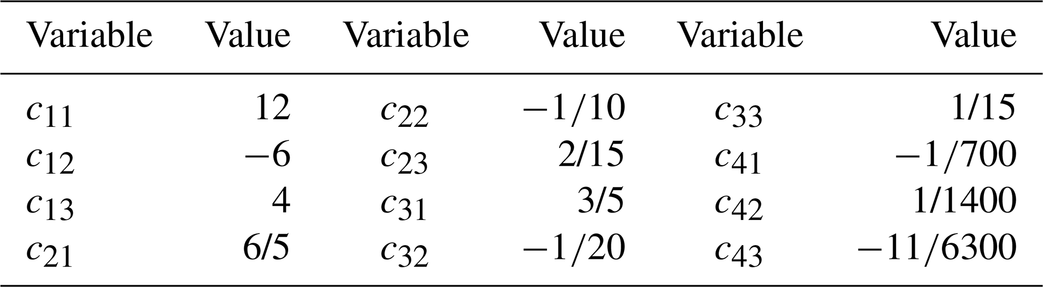
According to the nonlinear beam constraint model proposed by Awtar et al. (2007),
The matrix elements cij refer to the values provided by Awtar et al. (2007) as shown in Table 1. fx, fy, m, δx, and δy are dimensionless physical quantities defined as follows:
where L is the length of the compliant beam, E is the Young's modulus, I is the second moment of area of the compliant beam, and β is the inclination angle of the parallelogram compliant hinge.
Since the locking block is constrained by the slot and cannot rotate, α=0. Substituting into Eqs. (18) and (19), we obtain
The following geometric relationships exist:
where .
By solving the nonlinear system formed by Eqs. (21), (22), and (23), we get
where f=F0L2/EI, H(x0) is implicitly defined by the following equation:
The following method can be used to obtain an approximate expression for H(x0).
First, Eq. (25) is rewritten in the form of a cubic equation:
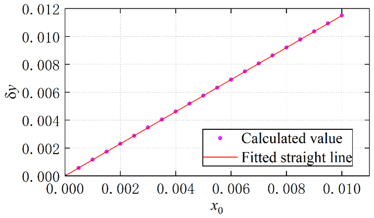
Substituting numerical values into the equation reveals that it has three real roots, the first two of which are negative. Therefore, only one root is physically meaningful. Due to the presence of parameter x0 in the coefficients, the root has a complex analytical form. Therefore, this paper calculates the real positive roots of the equation under several different values of x0, as shown in Fig. 4. From Fig. 4, a clear linear relationship between the positive root and x0 is observed. A linear fitting yields the following expression for the fitted root:
Substituting this into Eq. (24), the static model of the parallelogram compliant mechanism is obtained:
The expression for C(x) is as follows:
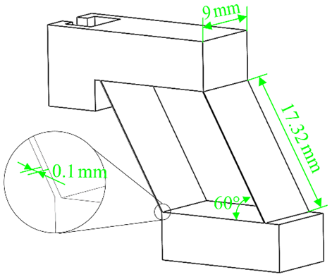
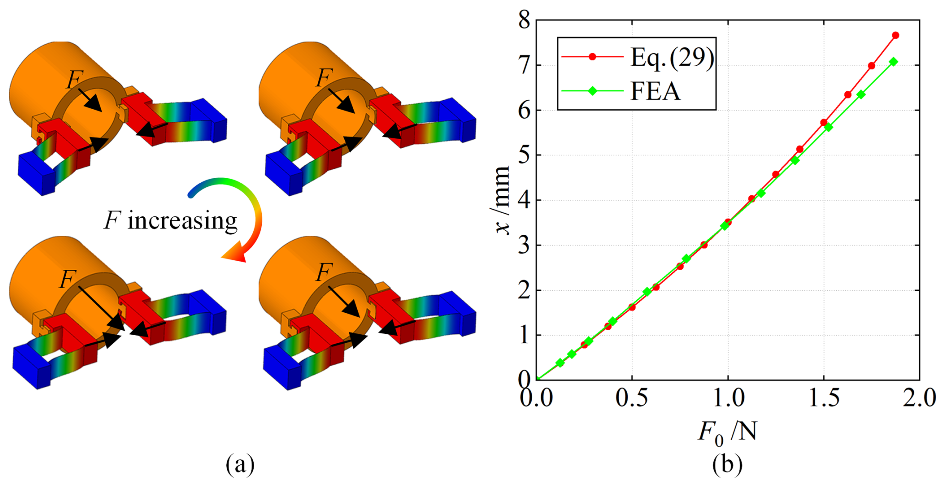
Figure 6Comparison between nonlinear finite element analysis and theoretical model. (a) Deformation cloud plot. (b) Deformation–displacement relationship.
3.3 Verification of the nonlinear static model of the compliant mechanism
To verify the nonlinear static model derived in this section, a nonlinear finite element simulation was conducted. The simulation tested a series of displacements under increasing thrust F. The geometric dimensions of the parallelogram compliant hinge are shown in Fig. 5, and the material used in both calculation and simulation is aluminum alloy 7075-T6. Figure 6a shows the total displacement cloud map from the simulation analysis. Figure 6b compares the simulation data with the results calculated using Eq. (29), with a maximum relative error within 10 %, indicating good modeling accuracy. The most likely source of error is that the nonlinear beam constraint model used in this study is not fully nonlinear. Instead, it has been partially linearized for the sake of simplifying the calculations and derivations. As shown in the curve diagram (Fig. 6b), it can be observed that as the deformation of the flexible beam increases, the error also increases. Additionally, the use of polynomial fitting during the model derivation introduces fitting errors.
Figure 7 shows the stress distribution when the maximum deformation occurs, i.e., x=7.5 mm, where the maximum stress is located at both ends of the compliant beam and reaches 439.4 MPa, which is below the allowable stress of 505 MPa.
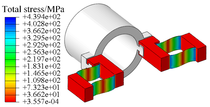
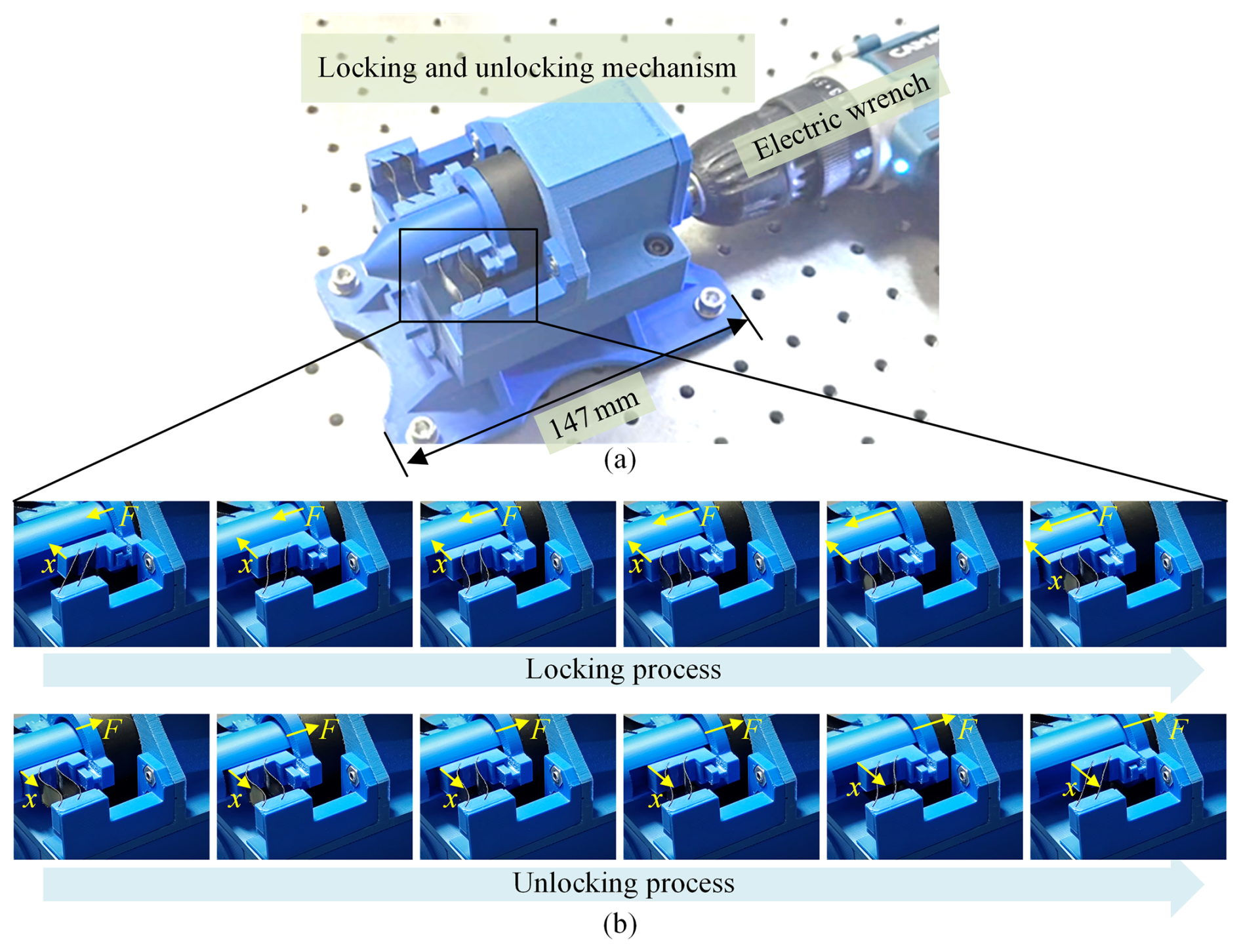
Figure 8Experimental setup and the locking and unlocking process. (a) 3D-printed physical prototype. (b) Partial schematic of the compliant hinge during the locking and unlocking processes.
To further verify the functionality of the proposed rigid–compliant-integrated locking and unlocking mechanism, a physical prototype was fabricated and tested. The locking and unlocking mechanism consists of 3D-printed components integrated with compliant flexural beams. The most prototype parts were obtained through 3D printing. The compliant elements are laser-cut from spring-steel shim stock, a material selected for its ability to undergo large elastic deformations while maintaining high fatigue resistance. The 3D-printed components and flexures are assembled using a combination of press-fitting and pinning, with adhesives applied where necessary, to form the prototype illustrated in Fig. 8a. This modular assembly facilitates easy replacement and adjustment of individual components during testing. The mechanism is actuated by an electric torque wrench, which drives an input shaft connected to a cam. As illustrated in Fig. 8b, when the motor rotates, it drives the lead screw to rotate, which in turn moves the threaded sleeve. The threaded sleeve pushes one end of the compliant module, causing deformation and planar motion of the compliant mechanism. This deformation results in the lateral movement of the locking block, which engages with the groove of the locking pin to complete the locking process. The unlocking process is similar: the motor rotates in the opposite direction, driving the same transmission chain to release the locking block from the locking pin, thereby completing the unlocking. The entire locking and unlocking process can be automated through electronic control.
Experimental observations confirm that the compliant beams achieve the intended large-stroke deformation without structural damage, validating the performance and functional robustness of the proposed mechanism.
A novel rigid–compliant-integrated locking and unlocking mechanism was developed in this study for applications such as modular vehicle connection and disconnection. For components requiring high load-bearing capacity and self-locking performance, rigid mechanisms were employed to ensure structural strength. For components with lower load-bearing demands but a need to avoid friction and wear, compliant mechanisms were introduced to simplify the structure while eliminating friction-related issues. The introduction of compliant mechanisms significantly simplified the structure of the end-effector transmission section but also introduced challenges in modeling. Due to the coupling between output displacement and force in compliant mechanisms, it is difficult to establish a purely kinematic model as is typically done with rigid mechanisms. Furthermore, the large deformations experienced by the compliant beams in this work rendered linear beam models inapplicable. Therefore, a nonlinear beam constraint model was adopted to establish the mechanical model of the parallelogram compliant hinge, which was then integrated with the Lagrangian dynamic model of the rigid mechanism to obtain a complete system model. By comparing the theoretical model with the finite element simulation model, the error under large deformation conditions was found to be within 10 %. A physical prototype was fabricated using 3D printing, and preliminary tests validated the functional feasibility of the proposed design. The proposed mechanism offers the following advantages:
-
Simple and reliable structure: the locking and unlocking mechanism fully integrates the strengths of both rigid and compliant components, simplifying the overall design and avoiding issues related to friction and wear.
-
Compact size: due to the reduced number of parts and compact component arrangement, the overall system maintains a small footprint. The 3D-printed prototype developed in this study measures only 147 mm × 97 mm × 100 mm.
-
Reliable locking: self-locking is achieved through a mechanical thread, ensuring a simple and dependable locking mechanism.
-
Automated connection and unlocking: the mechanism is driven by a motor, and automatic operation can be realized through simple motor control.
This research primarily focuses on configuration synthesis and feasibility analysis, demonstrating the viability of a rigid–compliant-integrated locking and unlocking mechanism. Future work will focus on the following aspects:
-
Improvement of the design. This paper presents a configuration design, and future efforts will focus on refining detailed dimensional design, conducting thorough experimental analyses, and performing iterative optimizations to achieve the optimal design outcome.
-
Consideration of the operating environment. Future research will examine the real-world operating conditions of modular vehicles, considering the effects of vibration, temperature variations, electrical connections, and other environmental factors on the device. This will lead to the design of a locking and unlocking mechanism capable of performing reliably in complex environments.
No data sets were used in this article.
HG and XS proposed the concept of the new locking–unlocking mechanism integrating compliant and rigid structures. HG carried out the detailed design, modeling, and simulations. YW, XY, and WL manufactured the prototype, designed the experiments, and performed the data analysis. HG prepared the article with contributions from all co-authors, and XS provided overall supervision.
The contact author has declared that none of the authors has any competing interests.
Publisher's note: Copernicus Publications remains neutral with regard to jurisdictional claims made in the text, published maps, institutional affiliations, or any other geographical representation in this paper. The authors bear the ultimate responsibility for providing appropriate place names. Views expressed in the text are those of the authors and do not necessarily reflect the views of the publisher.
This paper was edited by Haiyang Li and reviewed by two anonymous referees.
Awtar, S., Slocum, A. H., and Sevincer, E.: Characteristics of beam-based flexure modules, Journal of Mechanical Design, 129, 625–639, https://doi.org/10.1115/1.2717231, 2007.
Baviskar, D. D., Rao, A. S., Sollapur, S., and Raut, P. P.: Development and testing of XY stage compliant mechanism, International Journal on Interactive Design and Manufacturing (IJIDeM), 18, 5197–5210, https://doi.org/10.1007/s12008-023-01612-1, 2024.
Bayrak, A. E., Egilmez, M. M., Kuang, H., Li, X., Park, J. M., Umpfenbach, E., Anderson, E., Gorsich, D., Hu, J., Papalambros, P. Y., and Epureanu, B. I.: A System-of-Systems approach to the strategic feasibility of modular vehicle fleets, IEEE Transactions on Systems, Man, and Cybernetics: Systems, 50, 2716–2728, https://doi.org/10.1109/TSMC.2018.2827387, 2020.
Bian, K., Zhou, C., Zhao, F., Wu, Y., and Xiong, K.: Investigation of a shape memory alloy releasable mechanism applied in space environment, International Journal of Applied Electromagnetics and Mechanics, 64, 393–401, https://doi.org/10.3233/JAE-209345, 2020.
Chen, X., Xie, Z., Tai, K., and Tan, H.: Design of low parasitic motion microgripper based on symmetrical parallelogram mechanism, Sensors and Actuators A: Physical, 367, 115072, https://doi.org/10.1016/j.sna.2024.115072, 2024.
Choi, A. J., Park, J., and Han, J. H.: Automated aerial docking system using onboard vision-based deep learning, Journal of Aerospace Information Systems, 19, 421–436, https://doi.org/10.2514/1.I011053, 2022.
Cole, C. and Sun, Y. Q.: Simulated comparisons of wagon coupler systems in heavy haul trains, Proceedings of the Institution of Mechanical Engineers, Part F: Journal of Rail and Rapid Transit, 220, 247–256, https://doi.org/10.1243/09544097JRRT35, 2006.
Culpepper, M. L. and Anderson, G.: Design of a low-cost nano-manipulator which utilizes a monolithic, spatial compliant mechanism, Precision Engineering, 28, 469–482, https://doi.org/10.1016/j.precisioneng.2004.02.003, 2004.
Ding, B., Li, X., Li, C., Li, Y., and Chen, S.: A survey on the mechanical design for piezo-actuated compliant micro-positioning stages, Review of Scientific Instruments, 94, https://doi.org/10.1063/5.0162246, 2023.
Gao, G., Chen, W., Zhang, J., Dong, H., Zou, X., Li, J., and Guan, W.: Analysis of longitudinal forces of coupler devices in emergency braking process for heavy haul trains, Journal of Central South University 24, 2449–2457, https://doi.org/10.1007/s11771-017-3656-9, 2017.
Henning, S., Linß, S., Gräser, P., Theska, R., and Zentner, L.: Non-linear analytical modeling of planar compliant mechanisms, Mechanism and Machine Theory, 155, 104067, https://doi.org/10.1016/j.mechmachtheory.2020.104067, 2021.
Howell, L. L.: Compliant mechanisms, Edition: 1st, Wiley-Interscience, 047138478X, 2013.
Jackiewicz, J.: Coupler force reduction method for multiple-unit trains using a new hierarchical control system, Railway Engineering Science, 29, 163–182, https://doi.org/10.1007/s40534-021-00239-w, 2021.
Lee, J. and Han, J.: Separation and Release Devices for Aeronautical and Astronautical Systems: A Review, International Journal of Aeronautical and Space Sciences, 26, 131–161, https://doi.org/10.1007/s42405-024-00802-9, 2025.
Li, H., Wang, Q., Zhou, S., Zhao, H., Yu, G., Wang, J., Han, F., and Wang, C.: Design of a compliant locking and unlocking mechanism using problem decomposition-based method, Journal of Mechanical Design, 1–18, https://doi.org/10.1115/1.4068335, 2025.
Liao, M., Tran, N. D. K., and Wang, D.: Design of a compliant mechanism with collinear input and output, Mechanism and Machine Theory, 206, 105932, https://doi.org/10.1016/j.mechmachtheory.2025.105932, 2025.
Lin, J., Nie, Y. M., and Kawamura, K.: An autonomous modular mobility paradigm, IEEE Intelligent Transportation Systems Magazine, 15, 378–386, https://doi.org/10.1109/MITS.2022.3159484, 2023.
Luccarelli, M., Matt, D. T., and Spena, P. R.: Modular architectures for future alternative vehicles, International Journal of Vehicle Design, 67, 368–387, https://doi.org/10.1504/IJVD.2015.070412, 2015.
Ni, Z., Zhang, D., Wu, Y., Tian, Y., and Hu, M.: Analysis of parasitic motion in parallelogram compliant mechanism, Precision engineering 34, 133–138, https://doi.org/10.1016/j.precisioneng.2009.05.001, 2010.
Pandremenos, J., Paralikas, J., Salonitis, K., and Chryssolouris, G.: Modularity concepts for the automotive industry: A critical review. CIRP Journal of Manufacturing Science and Technology, 1, 148–152, https://doi.org/10.1016/j.cirpj.2008.09.012, 2009.
Qiang, H. and Wang, H.: Research on parasitic displacement and coupling error in lumped compliant parallelogram mechanism, Journal of the Brazilian Society of Mechanical Sciences and Engineering, 47, 376, https://doi.org/10.1007/s40430-025-05694-8, 2025.
Rösner, M., Lammering, R., and Friedrich, R.: Dynamic modeling and model order reduction of compliant mechanisms, Precision Engineering, 42, 85–92, https://doi.org/10.1016/j.precisioneng.2015.04.003, 2015.
Saab, W., Racioppo, P., and Ben-Tzvi, P.: A review of coupling mechanism designs for modular reconfigurable robots, Robotica, 37, 378–403, https://doi.org/10.1017/S0263574718001066, 2019.
Samadikhoshkho, Z., Saive, E., and Lipsett, M. G.: A review of compliant mechanisms for contact robotics applications, Robotics and Autonomous Systems, 186, 104902, https://doi.org/10.1016/j.robot.2024.104902, 2025.
Wagner, S., Cole, C., and Spiryagin, M.: A review on design and testing methodologies of modern freight train draft gear system, Railway Engineering Science, 29, 127–151, https://doi.org/10.1007/s40534-021-00237-y, 2021.
Xiong, R., Xu, X., Liu, Y., Du, S., Jin, L., Chen, F., and Wu, T.: A miniaturized MEMS accelerometer with anti-spring mechanism for enhancing sensitivity, Microsystems & Nanoengineering, 11, 42, https://doi.org/10.1038/s41378-024-00826-x, 2025.
Yue, H., Yang, Y., Lu, Y., Yang, F., Wu, J., Ruan, Q., and Deng, Z.: Research progress of space non-pyrotechnic low-shock connection and separation technology (SNLT): A review, Chinese Journal of Aeronautics 35, 113–154, https://doi.org/10.1016/j.cja.2021.07.001, 2022.
- Abstract
- Introduction
- Design of the rigid–compliant-integrated locking and unlocking mechanism
- Dynamic modeling of the rigid–compliant-integrated locking and unlocking mechanism
- Prototype experiment
- Conclusions
- Data availability
- Author contributions
- Competing interests
- Disclaimer
- Review statement
- References