the Creative Commons Attribution 4.0 License.
the Creative Commons Attribution 4.0 License.
 | 11 Feb 2026
Dynamics of herringbone planetary gear systems under mesh excitations with random cumulative pitch errors
Ying Du
Lan Liu
Geng Liu
Haoqin Zhang
Bingxi Yan
Bing Han
Herringbone planetary gear systems are extensively used in wind turbines and the marine industries, with strict requirements for the vibration level of gear systems. Mesh excitations, primarily driven by cumulative pitch errors, constitute the dominant source of system vibration and noise. Consequently, an improved model for calculating mesh excitations is proposed, considering the impact of random cumulative pitch errors. The validity of the model is confirmed through comparison of calculated and experimental results. On this basis, a lumped-parameter dynamic model of the herringbone planetary gear system with random cumulative pitch errors is established. Then, the impact of the random cumulative pitch errors on mesh excitations under different loading conditions is obtained. The dynamic characteristics of mesh pairs, considering the effects of random cumulative pitch errors, are investigated in detail. The findings suggest that random cumulative pitch errors exert a more pronounced influence on mesh excitations under low-loading conditions. In terms of the frequency spectrum of mesh forces, random cumulative pitch errors of the ring gear lead to the appearance of hunting tooth frequency and its harmonics, as well as rich sidebands around mesh frequency, assembly phase frequency, and their harmonics. The results can provide effective guidance for the low-noise and low-vibration design of herringbone planetary gear systems.
- Article
(10661 KB) - Full-text XML
- BibTeX
- EndNote


Herringbone planetary gear systems (HPGSs) have been widely used in industrial applications because of their high load capacity, compact structure, and high power density. However, HPGSs still experience noise and vibration problems despite these benefits. Internal excitations generated by meshing gear pairs are the major sources of noise and vibrations in HPGSs (Gong et al., 2022; Xu et al., 2024; Zhang et al., 2025). These excitations are closely related to the cumulative pitch errors of the tooth face. Therefore, it is of great importance to establish a model for internal excitations with cumulative pitch errors and then analyze the dynamic responses of HPGSs based on it.
Gear pairs' internal excitations are the primary sources of vibration and noise in gear systems. Because of this, they have received much attention from researchers. A new approach for the stiffness solution of herringbone gear pairs, including mounting errors and cracks, was put forward by Huang et al. (2025). Yang et al. (2022a, b) improved the calculation method for herringbone gear pairs' mesh stiffness considering time-varying backlash. A revised time-varying mesh stiffness (TVMS) calculation method that is affected by tooth roughness under elastohydrodynamic lubrication conditions was put forward by Wang and Zhu (2021, 2022). Pedrero et al. (2024) proposed an analytical model of TVMS and transmission errors (TEs) for internal gear pairs with profile modification. Hu and Zhang (2025) calculated the TE and TVMS of double-helical gear pairs, including tooth surface errors, using a novel slice model that they had proposed. Shehata et al. (2019) conducted a study on the effects of tooth microgeometry on the TE of helical gear pairs. Their study demonstrated that appropriate microgeometry modifications can effectively reduce TE. Chang et al. (2018) examined the role of tooth manufacturing errors in the TVMS and the composite mesh error of a helical gear pair. Their research denoted that both TVMS and composite mesh error are closely related to the actual total length of contact lines, which varies with load torque. Czakó et al. (2024) modeled the finite-element model of spur, helical, and herringbone gears with tip relief and extracted the TE, highlighting the importance of boundary conditions to TE. Some scholars investigated how pitch errors and cumulative pitch errors of gears affect mesh excitations. Under several load conditions, the index errors' repercussions for the loaded TE of a spur gear pair with a transmission ratio of 1:1 were investigated by Fernández-del-Rincón et al. (2016). Their results emphasized that index errors deserve considerable attention, as they may compromise the lifespan of gear systems. Considering the actual pitch errors of a helical gear pair with a transmission ratio of 1, Wang et al. (2017) analyzed the pitch errors' repercussions for TVMS for various tooth widths and loads. The study revealed that TVMS with pitch errors is lower than that in an error-free condition. Yuan et al. (2018) subjected a helical gear pair with a 1:1 ratio to a series of load cases, thus exploring the cumulative pitch errors' effects. Their findings presented that cumulative pitch errors can lead to smaller TVMSs, as well as the appearance of shaft frequency. Inalpolat et al. (2015) employed a dynamic model for a spur gear pair to explore the excitation mechanisms arising from tooth indexing inaccuracies. By incorporating measured indexing errors, the model can predict the dynamics of the system with improved accuracy.
Extensive research has been conducted into gear transmission systems' dynamics. Inalpolat and Kahraman (2010) developed a model of a planetary gear system, with the objective of predicting modulation sidebands of the system caused by gear manufacturing errors. Yang et al. (2023) established a coupled dynamic model of a marine gearbox, taking into consideration a range of factors pertinent to bearings, including bearing eccentricities. Subsequently, they explored the dynamic meshing force and bearing capacity under various operating conditions and with different bearing parameters. Chen et al. (2025) presented an advanced dynamic model of a herringbone star gear train having pin misalignment. They further explored the misalignment parameters that are conducive to the system. Li et al. (2024) explored the action of planet pin position errors on the fatigue reliability of planetary gear systems while accounting for their randomness. A dynamic model for an HPGS incorporating comprehensive components' excitations and interactions was proposed by Liu et al. (2023). Han et al. (2025), Bi et al. (2024), and Wang and Zhu (2023) incorporated the effects of gear cracks and pitting into their mesh stiffness models within a centralized parameter model for their respective planetary gear systems. Subsequently, these dynamic models were validated against experimental signals and employed to explore gear dynamics under such defects. Hu et al. (2023) developed a lumped-parameter model of a planetary gear system and verified its effectiveness. Based on this model, they further investigated the load-sharing performance (LSP) of the system under eccentricity errors and short-period errors. An examination of gear eccentricity's impact on gear trajectories under different combinations of manufacturing deviations was conducted by Huo et al. (2024). Their work emphasized the important impact of tooth number on the orbit shape of gears, considering eccentricity error. Sharma et al. (2024b, a, 2025) proposed a pioneering model coupling ship propeller shafts with magnetorheological dampers and validated the model experimentally. The behavior of the magnetorheological dampers can be precisely controlled using methods such as linear quadratic regulator and H∞ controllers. This model was shown to effectively reduce the longitudinal vibration of the propeller shafts. Guo and Fang (2020) carried out a statistical analysis of the random pitch error's repercussions for the vibrational displacement of a gear-rotor-bearing system and found that the stability of gear systems is significantly influenced by error distribution. Yang et al. (2022c) compared the effect of pitch errors and spalling fault on the dynamic response of a spur gear set. Their results indicated that the dynamic response of gear systems with spalling faults is sensitive to pitch errors, especially when gear accuracy is low. Chen et al. (2024) deduced the backlash for each mating tooth, taking into account tooth pitch errors, and explored the impact of pitch error phase on the LSP of a herringbone star gear train. Their analysis revealed that a suitable error phase between the two sides of the herringbone gear can effectively improve the load-sharing performance of the star gear system.
According to our literature survey, a few studies have analyzed the dynamic properties of gear systems under random cumulative pitch errors (RCPEs), which mainly focus on fixed-axis gear systems. Despite the potential of RCPEs to elicit intricate dynamic behaviors in HPGSs, there is a paucity of research in this area. While prior research has incorporated the cumulative pitch errors' impact, the spectral characteristics of the resulting system response, particularly new frequency components like hunting tooth frequency and the assembly phase frequency, along with associated modulation phenomena, have received limited attention. Moreover, the methods employed in the aforementioned studies to introduce the cumulative pitch errors into dynamic models of gear systems ignore the nonlinear relationships between cumulative pitch errors and mesh excitations. Although some scholars have studied the action of cumulative pitch errors on mesh excitations, their works predominantly focus on external gear pairs with a gear ratio of 1. In order to tackle the gaps in current research on the mesh excitations and dynamic characteristics of HPGSs, the succeeding structure of this paper is hereby proposed. Section 2 proposes an enhanced mesh excitation theoretical model, where the effect of the RCPE is involved. Then, the lumped-parameter dynamic model for the HPGS is established. Section 3 solves the mesh excitations with RCPE under different loading conditions. Section 4 sequentially studies the dynamic responses of each mesh pair under the mesh excitations with RCPE. Section 5 presents some conclusions from the results.
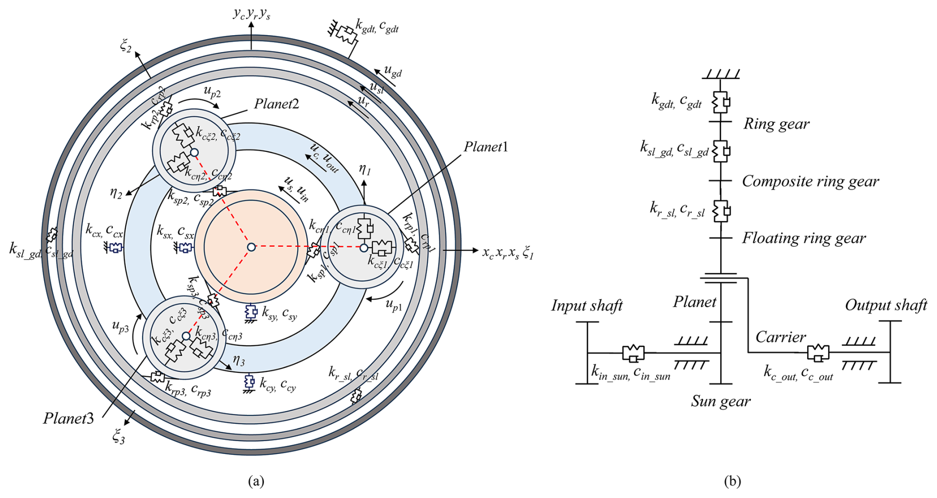
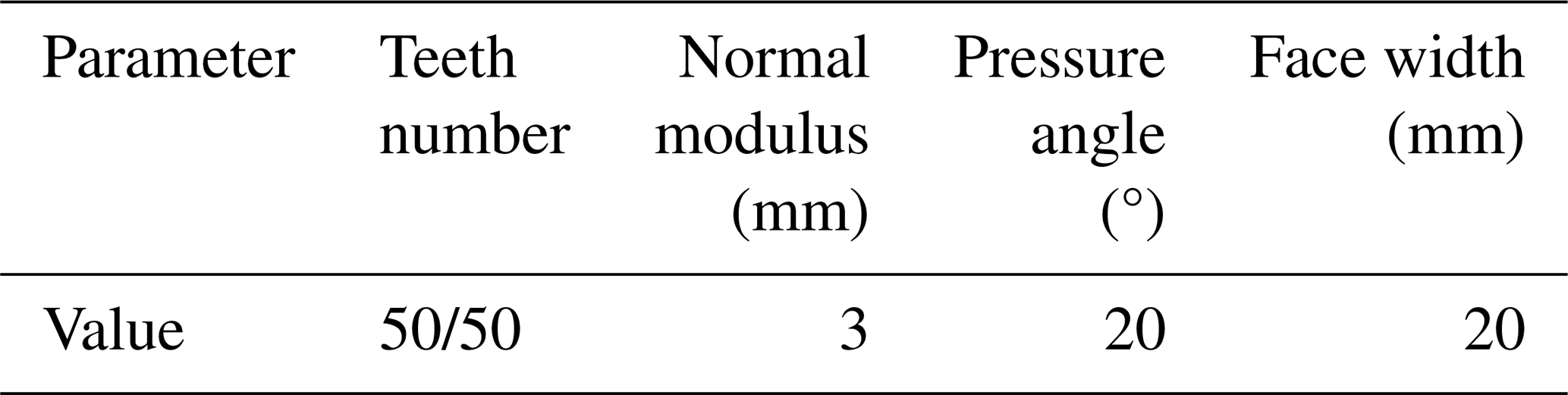
The HPGS is considered the object of study, which consists of the carrier, floating ring gear, sun gear, three planetary gears, composite ring gear, ring gear, and output shaft connecting the carrier. The model and its relevant parameters of the HPGS are given in Fig. 1 and Table 1, respectively. All the following studies are conducted based on these parameters.
2.1 Improved model for mesh excitations of herringbone gear pairs with RCPE
2.1.1 Mesh excitations without RCPE
In the dynamic model of the HPGS presented herein, the two sides of the herringbone gears are considered to be completely symmetrical. Therefore, to solve the internal excitations generated by herringbone gear pairs, it is necessary to calculate the internal excitations generated by helical gear pairs first. Here, the internal excitation calculation process of an internal gear pair is taken as an example, and the external excitation calculation process of external gear pairs is almost the same. Figure 2 shows the plane of action of an internal gear pair. In Fig. 2, B1B2 is the actual line of action in the transverse plane, and B2B3 is the face width of the helical gear pair.
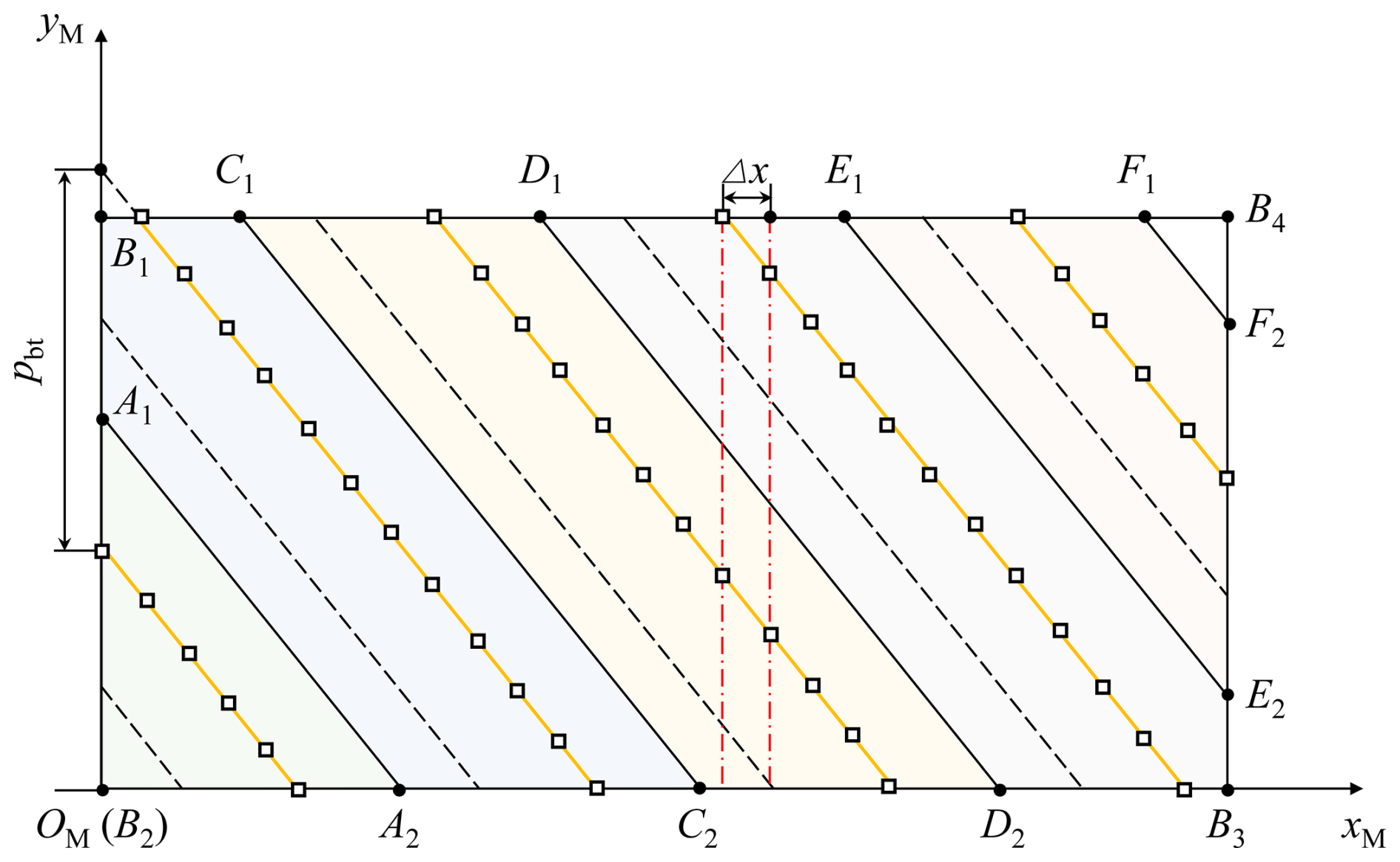
Utilizing Table 1, the total contact ratio εγ of the gear pair can be determined. From the total contact ratio, only N (N=ceil(εγ)) or N−1 tooth pairs will be in contact simultaneously during the gear engagement, and the total number of corresponding contact lines is M (M = N or N − 1). For the internal gear pair in Table 1, N = 6. In Fig. 2, the lines with hollow squares represent all the contact lines at this moment. The two neighboring contact lines are separated by a width equal to the transverse base pitch pbt along the yM direction. The hollow squares evenly distributed on each contact line represent the discrete contact points, and the distance between two adjacent discrete contact points along the xM direction is Δx. Assume that the total number of contact lines at this moment is M and the total number of discrete contact points on the mth contact line (where ) is nm. Then, the total number of all the theoretical discrete contact points is . On this basis, the internal excitation calculation process can be given.
Gear engagement can be interpreted as a contact problem involving two elastic bodies. When acted upon by an external force Fall, the two elastic bodies will move close together and gradually come into contact. When all contact lines in this moment are discretized into nall contact points, the general equation for the nth discrete contact point P (where ) on the mth contact line is as below:
where λmn is the global compliance of the nth discrete contact point on the mth contact line. Fmn is representative of the normal force exerted on point P. δhmn is the contact deformation. εmn is the initial separation distance before contact, which can be considered the sum of various errors. dmn is the residual distance after loading. LTE is the rigid-body approach, which is also the loaded transmission error.
Based on Eq. (1), the elastic deformation at every engagement point is comprised of two components. The former consists solely of the local contact deformation δhmn (Sainsot And et al., 2004):
where E represents Young's modulus. See Sainsot And et al. (2004) for details on other parameters.
The latter is the global compliance λmn, which can be written as
where λbmn, λsmn, λamn, and λfmn are the bending compliance, shear compliance, axial compression compliance, and fillet-foundation compliance, respectively. Superscript g denotes the driving (g=1) or driven (g=2) gear.
By evenly slicing helical gears along the axial direction at a distance of Δx (see in Fig. 2), many thin pieces treated as narrow-faced spur gears can be obtained. Figure 3 shows the transverse models for the narrow-faced spur gears.
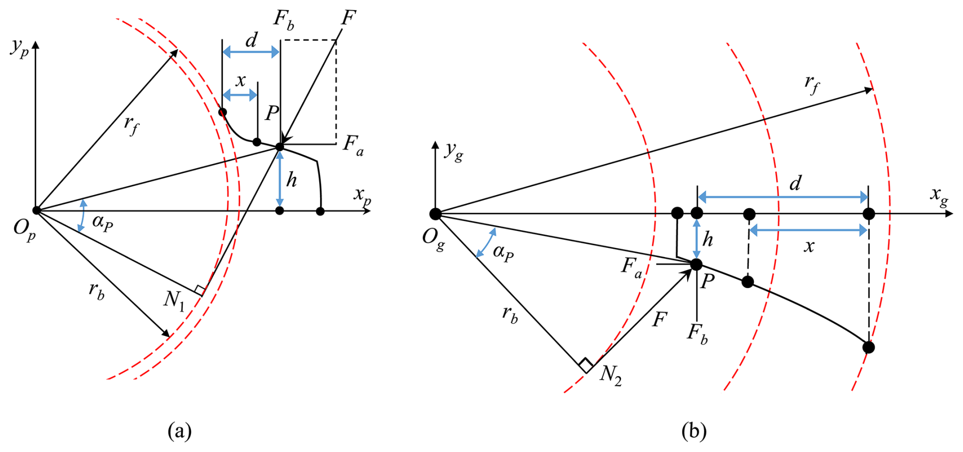
On this basis, the location of the discrete engagement point P on the corresponding equivalent spur gear can be applied to derive the corresponding bending compliance λbmn, shear compliance λsmn, axial compression compliance λamn, and the foundation compliance λfmn of the gear body using the potential energy method as follows (Yang et al., 2022a):
where d and h are the horizontal and vertical distances from P to the dedendum circle and the central line of the tooth, respectively. x denotes the distance from the dedendum circle to the section. The remaining parameters can be referred to in Wang and Zhu (2022).
Substituting Eqs. (2) and (3) into Eq. (1) yields the linear equality constraint equation for the contact point P. Similarly, the linear equality constraint equations for the remaining contact points can be obtained based on Eq. (2). On this basis, the linear equality constraint equations in matrix form can be obtained as follows:
where is the global compliance matrix for the gear pair. , , , and are, respectively, the vectors of the contact forces, contact deformations, initial separation distances, and residual distances for all contact points.
In addition, the following relationships must be satisfied between , , and the total mesh force Fall:
Equations (5) and (6) form a system of equations of order nall+1 with 2nall+1 unknowns. One unknown is the LTE, while the others include the load distribution and the residual distances at all contact points. However, the system of equations has a unique solution under the action of the contact condition in Eq. (6). According to the convergence criterion and the iteration algorithm established by Chang et al. (2015), the force vector and LTE can thus be extracted by solving Eqs. (5) and (6) using this iteration algorithm. The mesh stiffness km is then calculated in the following manner:
where kmn is the stiffness of each contact point pair.
2.1.2 Mesh excitations with RCPE
The algebraic disparity between the real and ideal arc lengths of any tooth space is designated as the cumulative pitch deviation. The cumulative pitch error of a gear tooth flank, as one of the essential inspection items after gear manufacturing, will change the initial separation distance between each contact point pair. When the gear deformation induced by loading cannot compensate for the excessive initial separation distance caused by errors at a theoretical contact point pair, that pair will not be in contact. This subsequently affects the engagement status, resulting in alterations in the mesh stiffness and transmission errors. The cumulative pitch error of the kth gear tooth can be defined as follows (Chen et al., 2024):
where zg represents the number of teeth of the driving/driven gear. is the tooth number of the initial matching position of each gear. is the cumulative pitch deviation of the driving/driven gear, which can be expressed as follows (ISO, 2013):
where the definitions of dp, mn, and A can be found in ISO (2013).
Based on the relationship between the pitch error of the kth tooth and the cumulative pitch deviations of the two neighboring teeth, can be written as follows (Inalpolat et al., 2015):
Therefore, the components of cumulative pitch errors and single pitch errors that are projected in the direction of the initial separation distances are as follows:
where αt and βb represent the transverse pressure angle and the base circle helix angle of gear pairs, respectively.
Let the tooth pair entering the meshing process be designated as tooth pair 1, where the teeth represent the first teeth of both gears. Consequently, the teeth of each gear and the tooth pairs are sequentially numbered according to their contact sequence, as shown in Fig. 4.
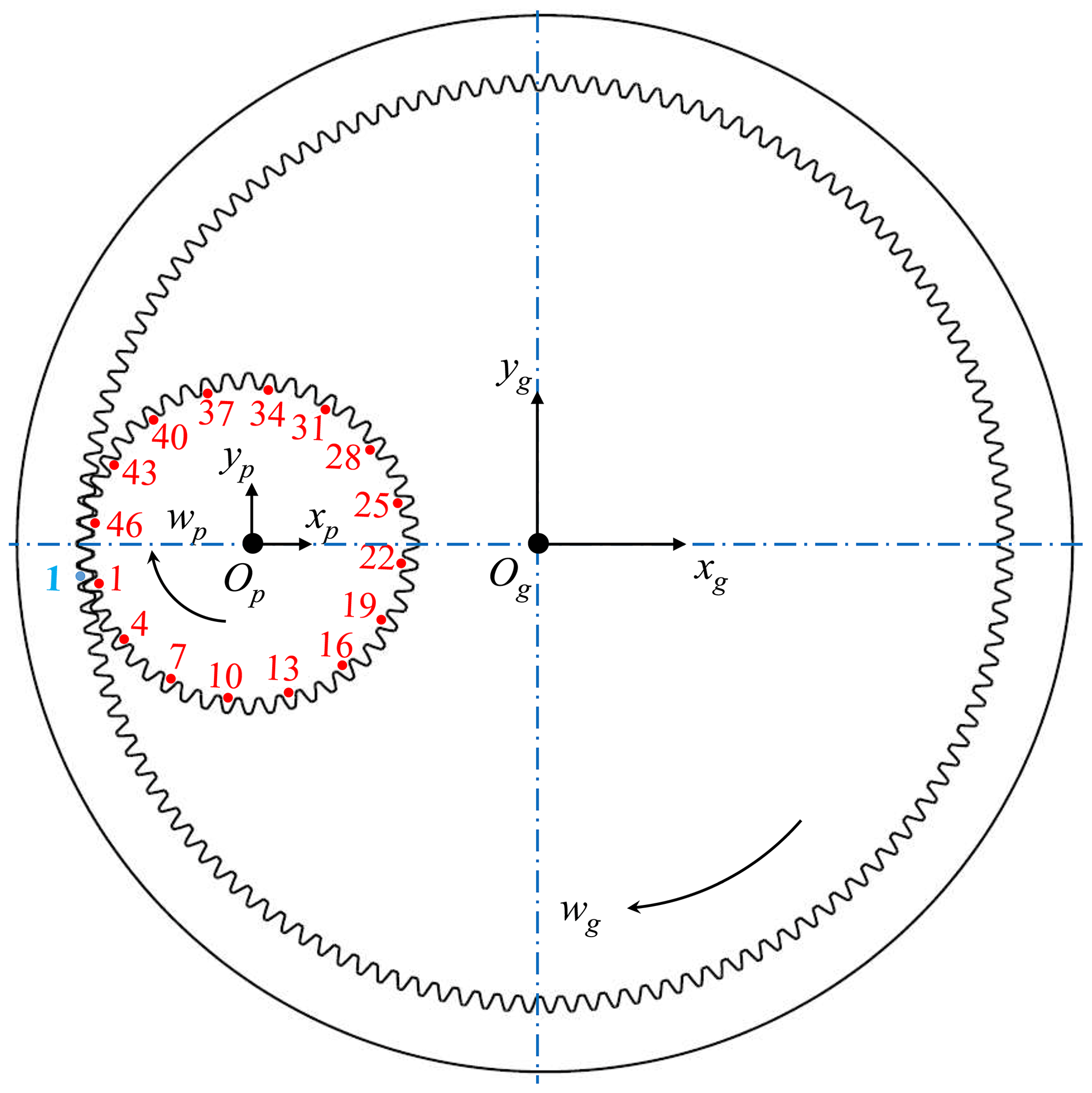
It must be noted, however, that the teeth pitch errors exhibit variation; thus, the number of meshing cycles required for tooth pair 1 to mesh again is Num:
where gcd(z1,z2) is the highest common factor of z1 and z2.
It is also essential to further determine the numbering of the tooth pairs engaging at any moment, as well as the locations of the contact lines of each tooth pair on the plane of action.
Figure 5 shows the numbering rules of meshing areas on the plane of action. According to the value of εγ, the plane of action can be divided into N areas, as depicted in Fig. 5. The solid lines inside the plane signify the critical contact lines, which are parallel to each other, and the distance between two adjoining lines is equal to pbt along the yM direction. By sequentially numbering these N areas in the direction from B2 to B4, the corresponding areas into which the contact lines of all tooth pairs may fall can be determined.
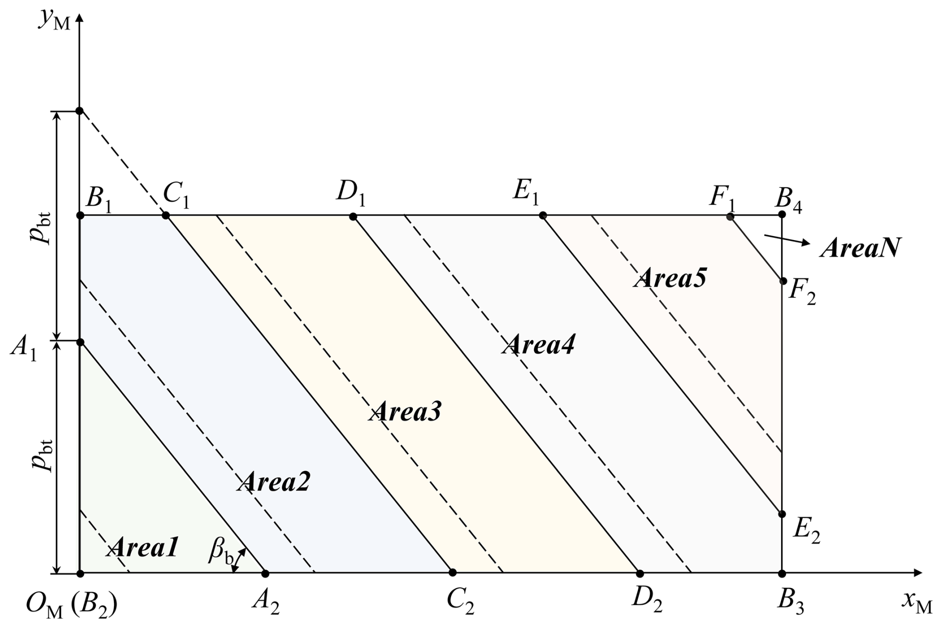
Figure 5Numbering rules for meshing areas containing contact lines of tooth pairs during one meshing period.
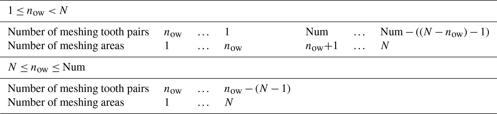
Based on the numbering rules of meshing areas, it is imperative to ascertain the number of all tooth pairs that may engage in each meshing cycle. Then, the internal excitations considering cumulative pitch errors can be solved.
The numbering rules of meshing tooth pairs and meshing areas in Table 2 reflect the complete engagement processes of the tooth pair now. If the tooth pair is just ready to come into contact, then in this meshing cycle, the tooth pairs that may engage are tooth pair now, tooth pair , tooth pair 1, tooth pair Num, tooth pair , and tooth pair , while the corresponding contact lines on these tooth pairs will fall in area 1, area 2,…, area now, area now+1, area , and area N, respectively, as shown in Fig. 5. If the tooth pair now(N≤now) is just ready to come into contact, then in this meshing cycle, the tooth pairs that may engage are tooth pair now, tooth pair , and tooth pair , while the corresponding contact lines on these tooth pairs will fall in area 1, area 2,…, and area N, respectively.
Table 2Numbering rules of meshing teeth pairs and meshing areas.
According to the relationships and Eq. (11), the initial separation distance of each contact point pair under Num meshing cycles, arising from cumulative pitch errors, can be calculated. By substituting these computed values into the relevant terms of {ε}nall × 1 in Eq. (5), the internal excitations that incorporate the influence of cumulative pitch errors can be derived.
In published works, the internal excitations generated by gear meshing are usually treated as short-term excitations, while the minimum computation time is the meshing period Tm. However, the shortest computation duration required is Th to consider the impact of cumulative pitch errors on the internal excitations, according to Eq. (12):
where fht denotes the hunting tooth frequency (the frequency at which two designated teeth on the driving and driven gears come into contact once). Tht is the hunting tooth period corresponding to fht.
If the tooth numbers of the gear pair are not relatively prime, it can be observed from Fig. 4 that each tooth on the pinion will make contact with teeth on the wheel. This phenomenon is expected, given the cumulative pitch errors' effect. Consequently, the impact of pitch error in a single tooth on the pinion will only be transmitted to the teeth on the wheel, which means that a given tooth on the pinion engages exclusively with a specific set of teeth on the wheel. This can potentially elevate the risk of failure and uneven distribution and lead to the appearance of assembly phase frequency fap (the frequency at which the designated driving gear tooth and any individual tooth within the specified subset of teeth on the driven gear come into contact once):
where fm is the meshing frequency of the HPGS.
2.1.3 Experimental validation of the proposed model
The Ohio State University conducted measurements of gear transmission errors using an open-architecture gearbox (Inalpolat et al., 2015). Their tests employed unity-ratio spur gear pairs with cumulative pitch errors. Specifically, the driving gear had a single tooth with a 15 µm pitch error, while the driven gear was free of pitch errors. The gear pair parameters are given in Table 3.
Table 3Basic parameters of the gears (Inalpolat et al., 2015).
To ascertain the efficacy of the proposed model for mesh excitations considering cumulative pitch errors, the loaded transmission error calculated by the proposed method at a load torque of 200 N m−1 is compared with the measured transmission error given in the literature (Inalpolat et al., 2015), as shown in Fig. 6. It can be observed that the LTE obtained by the proposed model herein exhibits high consistency with the experimental results. This comparison not only validates the proposed method but also demonstrates its capability to effectively consider the impacts of pitch errors and cumulative pitch errors on mesh excitations.
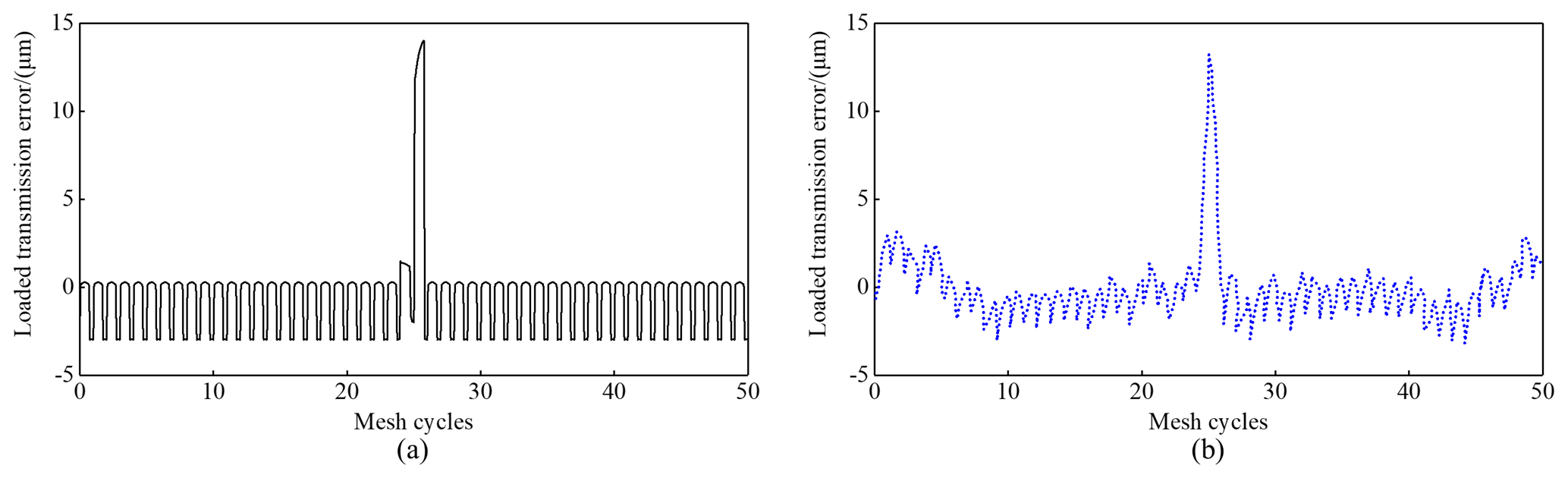
Figure 6Comparison of the (a) calculated transmission errors and (b) experimental transmission errors (Inalpolat et al., 2015) of the gear pair with cumulative pitch errors.
2.2 Dynamic model of the HPGS
This section models the bending–torsion–axial coupled dynamic model of the HPGS. The overall degrees of freedom (DOFs) of the planetary system are q=47, and the detailed DOFs are written as
where the superscript h means the left (h=L) and the right (h=R) sides of the herringbone gear. xl, yl, zl, ξi, ηi, and zi mean the translational displacements for the carrier (l=c), the floating ring gear (l=r), the sun gear (l=s), and the ith planet gear (), respectively. ul and upi correspond to the respective torsional displacements. Np means the planet gears' total number. uj denotes the rotational displacement for the input shaft (j=in), composite ring gear (j=sl), ring gear (j=gd), and output shaft (j=out).
The elastic deformation of the sun-planet and ring-planet gear pairs along the corresponding mesh line direction is as follows:
where and describe the angles formed by the plane of action of the ith sun-planet and ring-planet mesh pair and the positive direction of the y axis. is the position angle for planet gear i. espi(t) and erpi(t) represent the LTE of the ith sun-planet and ring-planet mesh pair, respectively, incorporating the action caused by the RCPE. When h=R, then .
Considering the action of the cumulative pitch error, mesh forces and for external and internal mesh pairs are formulated as
where kspi, krpi, cspi, and crpi are indicative of the mesh stiffness and damping, considering cumulative pitch errors separately.
The elastic deformation on the ith planet-carrier mating pair is defined by
The corresponding bearing forces , , and along the ξi, ηi, and z directions due to motions of the planet i and carrier are defined by
where kcξi, kcηi, kczi, ccξi, ccηi, and cczi are the corresponding stiffness and damping.
Thus, the equations of motion for the HPGS can be derived.
Here and stand for the equivalent mass and actual mass of the corresponding component, respectively. The input and output torques are specified by Tin and Tout, respectively. klx, kly, and klz and clx, cly, and clz indicate the supporting stiffness and damping of the corresponding component, respectively. , , , and denote the bending, compressive, and torsional stiffness between the left and right helical gears of the corresponding herringbone gear; , , , and are the corresponding damping. rin, rbs, rsl, rbr, rout, and rgd represent the radii for the input shaft, the sun gear's basic circle, the composite ring gear, the floating ring gear's basic circle, the output shaft, and the ring gear, respectively. rc represents the distance from the planet center to the carrier center. kr_sl, kc_out, ksl_gd, and kgdt denote the torsional stiffness between the floating ring gear and the composite ring gear, the carrier and the output shaft, the composite ring gear and the ring gear, and the ring gear to the ground, respectively. The corresponding torsional damping is defined as cin_sun, cr_sl, cc_out, csl_gd, and cgdt, respectively.
Analysis of time-domain mesh excitations with RCPE
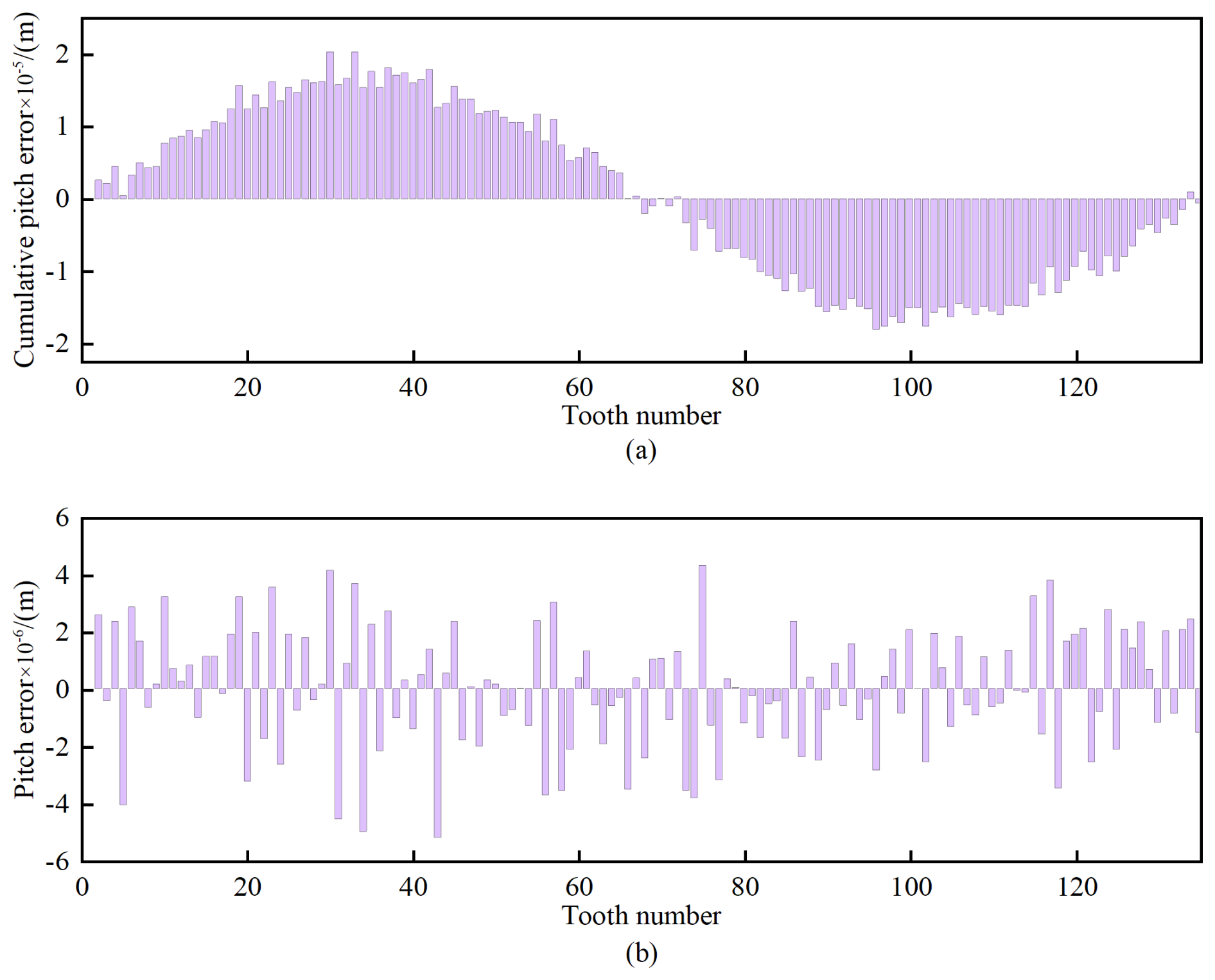
To realistically model the impact of cumulative pitch errors on internal excitations, their stochastic characteristics should be incorporated due to the presence of machining errors. Drawing parallels with involute spline indexing error analysis (Hong et al., 2015), this study defines RCPE as a composite function combining sinusoidal components, generated by Eq. (8), and normally distributed variations. The probabilistic characteristics are modeled through normal distribution parameters λ ∼ (0,32), representing zero-mean deviations with a standard deviation of 3 µm. By superimposing this normal distribution with the sinusoidal component, the RCPE of gears can be generated. Equation (9) gives the error amplitude for gears manufactured to Grade 5 precision standards: 16.04 µm, representing the peak magnitude of RCPE. Figure 7 presents the RCPE distribution and the corresponding pitch errors of the floating ring gear.
In practical engineering, HPGSs are widely used instead of fixed-axis gear systems with a transmission ratio of 1 (Fernández-del-Rincón et al., 2016; Talbot et al., 2016; Wang et al., 2017). For the sake of facilitating the calculation and examining the impact of cumulative pitch errors on the HPGS's response, it is proposed that only the RCPE of the floating ring gear be incorporated into the model for internal excitations. Then, the mesh excitations of the internal gear pair in the HPGS are investigated for varying loading cases. The value of Th, which can be determined by Eq. (13) and the working conditions in Table 1, equals 0.04 s. The input powers are 3500, 5250, 7000, 10 500, and 17 500 kW, and the corresponding forces transmitted per unit width (wt) (Chang et al., 2015) are 100, 150, 200, 300, and 500 N mm−1, respectively.
Figure 8 delineates the evolution of internal gear pair mesh stiffness at different wt. It appears evident that the mesh stiffness exhibits significant fluctuations when the value of wt is 100 N mm−1, with the mesh stiffness being reduced in comparison to its value at higher wt. This phenomenon is attributed to the consideration of the RCPE of the internal gear, which creates an initial separation distance between each theoretical contact point pair. Under light-wt conditions, some of the theoretical contact point pairs still have residual distances, indicating the appearance of partial contact loss. As wt gradually increases from 100 to 500 N mm−1, the initial separation distances are progressively compensated for by the elastic deformation under load. Consequently, the active contact zone gradually extends to the entire tooth surface, resulting in a more stable mesh stiffness curve that trends similarly.
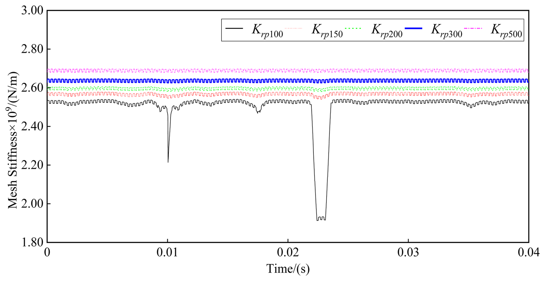
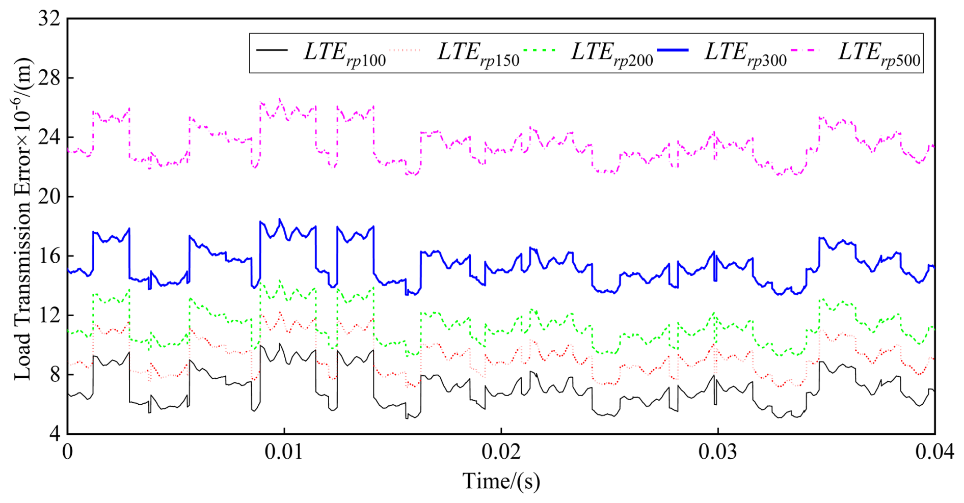
Figure 9 illustrates the shapes of the LTE of the internal gear pair varying according to differing wt conditions. The LTE curves, when subjected to varying wt conditions, are invariably identical to each other, although the magnitudes become progressively higher as wt increases. The fundamental reason lies in the enhanced deformation of gear teeth resulting from the increase in wt, which contributes to the LTE values.
Based on Eqs. (13) and (14) and Table 1, the values of the hunting tooth frequency fht (25 Hz), assembly phase frequency fap (1125 Hz), and gear meshing frequency fm (3375 Hz) for the internal mesh pair are computed. The spectral characteristics of the internal mesh pair's mesh stiffness, when wt is at 100, 150, and 300 N mm−1, are presented in Fig. 10a–c separately. In Fig. 10, due to the RCPE of the floating ring gear, the mesh stiffness evinces complex frequency spectra. The frequency components of hunting tooth frequency and assembly phase frequency caused by cumulative pitch errors are pronounced.
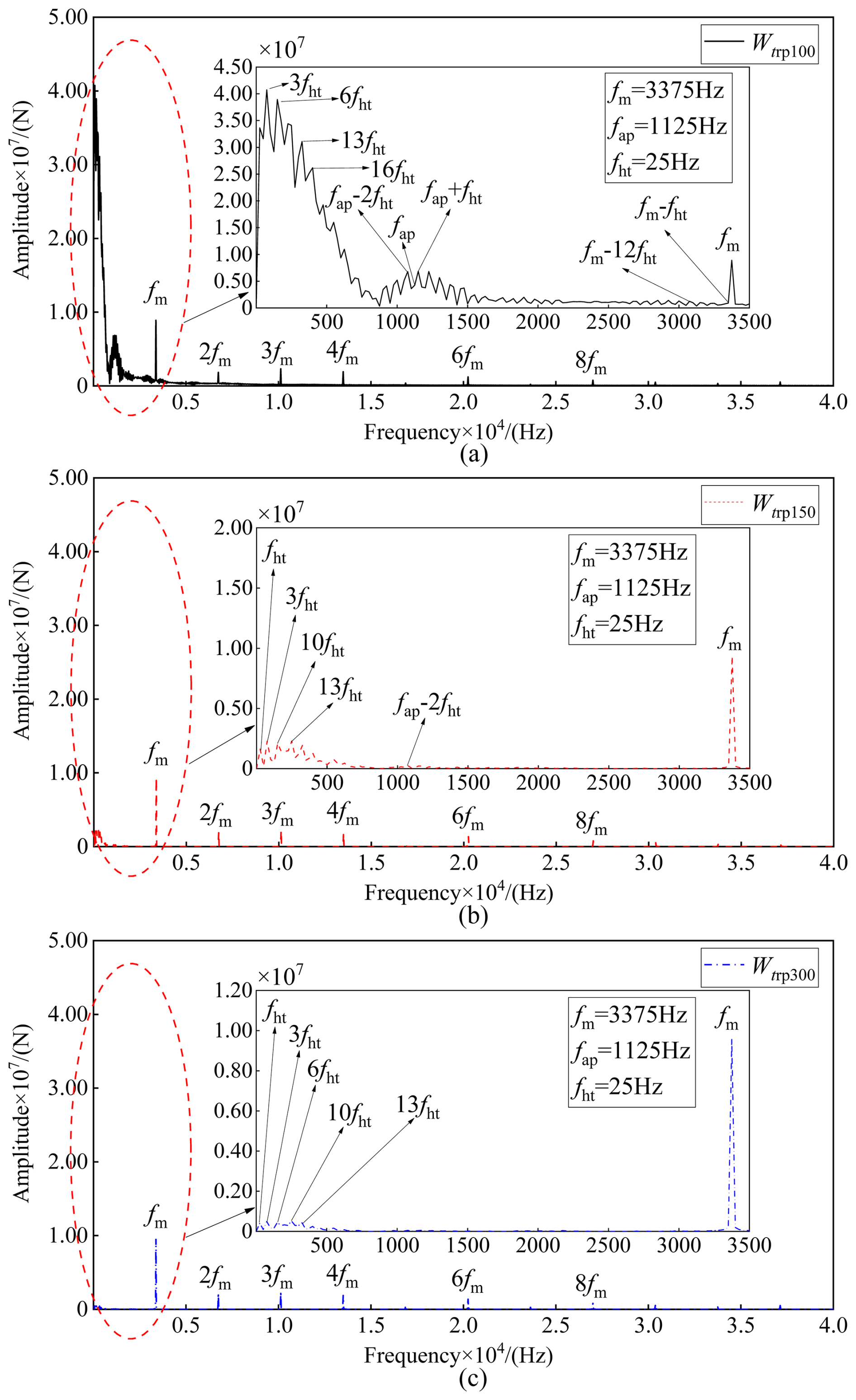
Figure 10Spectrum of the mesh stiffness of ring planets with RCPE at (a) wt = 100 N mm−1, (b) wt = 150 N mm−1, and (c) wt = 300 N mm−1.
Figure 10a shows the mesh stiffness spectrogram when wt is 100 N mm−1. The frequency spectrum of the mesh stiffness is enriched due to the RCPE of the floating ring gear. Moreover, the low-frequency band shows obvious frequency components at fht and its harmonics. At the same time, an obvious assembly phase frequency also appears. In addition, fm and fap are both modulated by fht and its harmonics, resulting in the abundant sidebands fap±nfht and fm±nfht () around them. The full-frequency spectrum depicted in Fig. 10a shows that the most predominant frequency is the third harmonic frequency (3fht), with an amplitude of 4.074 × 10⁷ N m−1. Additionally, the amplitude of the meshing frequency is 8.898 × 10⁶ N m−1. Figure 10b shows the mesh stiffness spectrogram when wt is 150 N mm−1. It can be observed that as wt increases from 100 to 150 N mm−1, the richness of the frequency components in the low-frequency band, influenced by random cumulative pitch errors, decreases, and the corresponding amplitude also decreases. However, fht and its harmonics, together with the sidebands fap±nfht, can still be observed in the partially enlarged view of Fig. 10b, whereas the sidebands around the meshing frequency nearly disappear. Different from the scenario observed at wt = 100 N mm−1, the most predominant frequency shifts to the meshing frequency, exhibiting an amplitude of 9.34 × 10⁶ N m−1, which is followed by the 3fht frequency with an amplitude of 2.277 × 10⁶ N m−1. Compared to the corresponding results obtained at wt = 100 N mm−1, the amplitude of fm has increased by 4.97 %, while that of the 3fht frequency has decreased by 94.41 %. The frequency spectrum corresponding to the mesh stiffness at wt = 300 N mm−1 is presented in Fig. 10c. It was found that compared with the results at wt = 150 N mm−1, a notable reduction in the low-frequency components within the spectrum is observed. However, the hunting tooth frequency and its harmonics still exist in the partially enlarged view of Fig. 10c, whereas the meshing frequency and assembly phase frequency have no obvious sidebands. Moreover, the most predominant frequency component remains the meshing frequency, and the amplitude 9.564 × 10⁶ N m−1 changes slightly from that obtained in wt = 100 N mm−1. Additionally, the amplitude of the 3fht frequency changes to 4.904 × 10⁵ N m−1, with a decrease of 78.46 %.
Comparing the above three cases, it is found that when wt is low, the fundamental frequencies in the spectra include fht, fap, and fm and their harmonics, together with sidebands around fap and fm and their multiples. As wt increases, the frequency components related to fht and fap gradually decrease until the frequency components of the spectra include only fm and its harmonics. The reason is that with the increase in wt, the area of the contact loss due to the cumulative pitch errors of the floating ring gear gradually decreases until the real contact zone gradually extends to the entire theoretical contact zone.
5.1 Dynamic response of the HPGS without RCPE
The succeeding sections examine the dynamic characteristics of the HPGS under the influence of RCPE. To isolate the specific influence of RCPE in the floating ring gear, the dynamic model in this study does not account for other sources of asymmetry. Consequently, it does not capture potential differences in the responses of individual sun-planet or ring-planet branches. Hence, under the current assumptions, the dynamic mesh forces are identical across all external gear pairs and across all internal gear pairs, regardless of whether RCPE is included in the floating ring gear. As wt increases, the influence of the RCPE on the internal excitations decreases; hence, a relatively lower wt value is adopted in our study. The input power used in this instance is set as 3500 KW, which means wt = 100 N mm−1.
The dynamic responses of the HPGS were acquired through the Fourier series method. Furthermore, a 3D model of the HPGS was constructed via SolidWorks and imported into the SIMPACK multi-body dynamics software, as shown in Fig. 11. Within SIMPACK, constraints were applied to define the DOFs of each component, and force elements were applied to enable force transmission between them. Operating conditions consistent with Table 2 were established: the sun gear input speed and the output shaft load torque were set to 6692.2 rpm and 2.2283 × 10⁴ N m−1, respectively. Solver settings configured the simulation time to 2 s and the sampling frequency to 168 750 Hz. The solution method used here is the SODASRT2 integration method. Finally, the steady-state meshing force results from the last 0.04 s of the dynamic simulation were extracted. Mesh forces of the HPGS, excluding the action from random cumulative pitch error effects experienced by the floating ring gear, are illustrated in Fig. 12. A comparison analysis of the dynamic mesh forces calculated with the current dynamic model and those from the multi-body dynamics software SIMPACK, as illustrated in Fig. 12, shows a strong correlation. This alignment effectively confirms the reliability of the HPGS dynamic model.
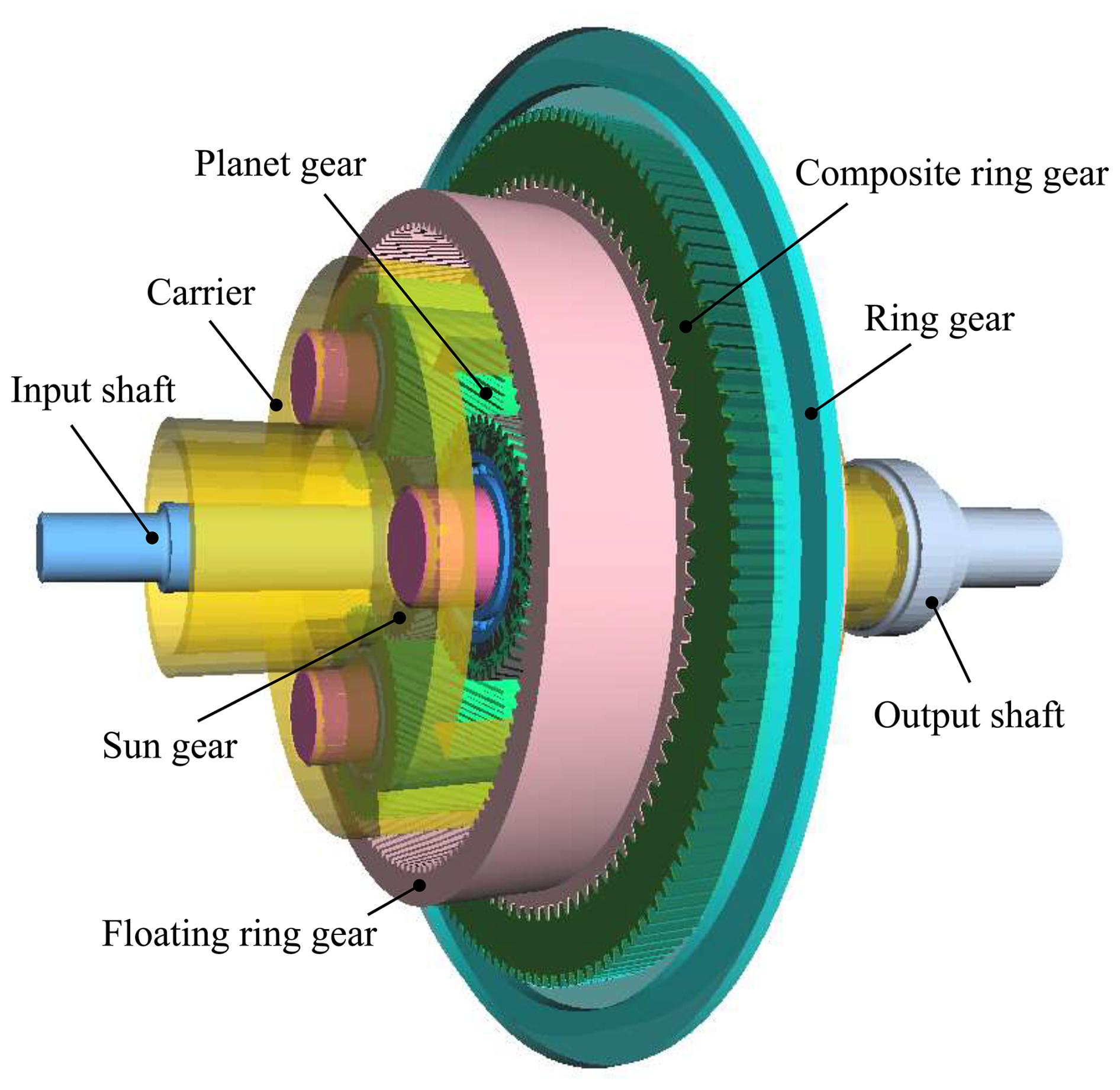
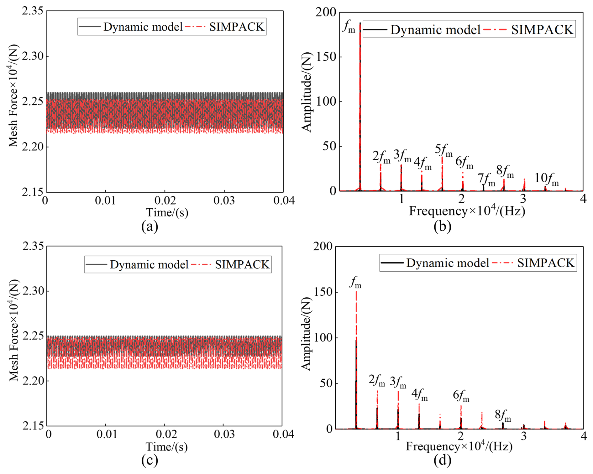
Figure 12Dynamic mesh forces without pitch error at wt = 100 N m−1: (a) time-domain sun-planet meshes, (b) frequency-domain sun-planet meshes, (c) time-domain ring-planet meshes, and (d) frequency-domain ring-planet meshes.
The time-domain mesh forces, Fsp and Frp, over a carrier cycle obtained using the dynamic model are plotted in Fig. 12a and c, respectively. Figure 12b and d show the frequency spectra corresponding to Fig. 12a and c, respectively. The average mesh forces of all these mesh pairs are around the value of the theoretical mesh force of 2.240 × 10⁴ N. The fluctuation amplitudes of Fsp and Frp are 390 and 220 N, respectively. Moreover, without the effects of any errors, the frequency spectrum of mesh pairs' mesh forces only comprises fm and its harmonics, as demonstrated in Fig. 12b and d.
5.2 Dynamic response of the HPGS with RCPE
In light of the floating support design of the ring gear in the current system, the focus of this study on the low-frequency dynamic behavior excited by random cumulative pitch errors, and the need to constrain computational cost, the subsequent dynamic response analysis considers only the random cumulative pitch error of the floating ring gear. Figure 13 shows the mesh forces Fsp, considering only the floating ring gear's random cumulative pitch errors. After accounting for the influence of the floating ring gear's random cumulative pitch errors, the three external mesh pairs still experience the same dynamic mesh force at any moment. However, the evolution of the mesh forces becomes unstable, and the minimum repetition period of the mesh force curves is no longer the mesh period Tm = 0.000296 s but becomes the hunting tooth period Th = 0.04 s. Additionally, the average mesh forces of all these mesh pairs remain around 2.240 × 10⁴ N, but the fluctuation amplitude of Fsp is 1.1579 × 10⁴ N, which increases significantly compared to the results in the ideal state (shown in Fig. 12a).
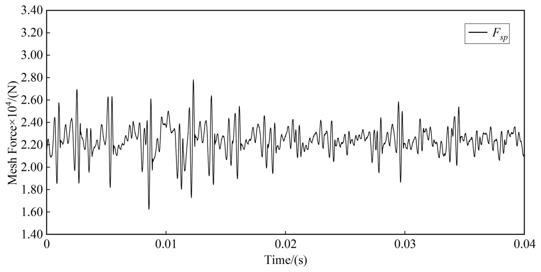
Figure 13Dynamic mesh forces of sun-planet mesh pairs only, with random cumulative pitch errors in the time domain.
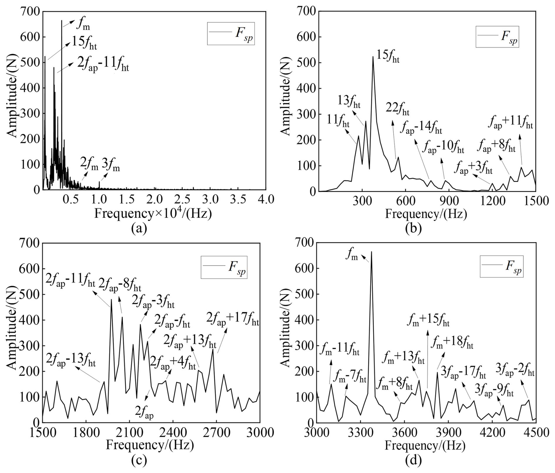
Figure 14Sun-planet dynamic mesh forces only, with random cumulative pitch errors in the frequency domain: (a) full-frequency spectra, (b) partially enlarged view of the spectra from 0–1500 Hz, (c) partially enlarged view of the spectra from 1500–3000 Hz, and (d) partially enlarged view of the spectra from 3000–4500 Hz.
Figure 14 shows the fast Fourier transform (FFT) spectrum of Fsp. A comparison of Fig. 14a with Fig. 12b reveals that the action from the internal excitations of the ring-planet meshes, considering the random cumulative pitch errors of the floating ring gear, is transmitted to the sun-planet meshes through the interaction between each component, so that, in addition to fm and its harmonics, the dynamic mesh force spectra of the sun-planet mesh pairs also present complex low-frequency components. In the full-frequency spectra, as shown in Fig. 14a, the predominant frequency components are fm, 15fht, and 2fap–11fht, and the corresponding amplitudes are 665, 523.8, and 480.6 N, respectively. As shown in Fig. 14b–d, the partially enlarged view of the full-frequency spectra reveals the presence of obvious fht and its harmonics. In addition, rich sidebands manifest around fm, fap, and their harmonics, and the interval between two adjoining sidebands equals nfht (n is any integer greater than 0).
Figure 15 shows the mesh forces Frp, considering only the floating ring gear's random cumulative pitch errors. Similar to the changes in the mesh forces Fsp, the three internal mesh pairs still undergo the same dynamic mesh force at any moment under the random cumulative pitch error of the floating ring gear. Furthermore, the minimum repetition period of the mesh force curves is also the hunting tooth period Th. Additionally, the average mesh forces of all these mesh pairs remain around 2.240 × 10⁴ N. However, after considering the impact of the cumulative pitch errors, the fluctuation of Frp, which is 9.0501 × 10⁴ N, is far larger than that of the external mesh pairs. This is due to the incorporation of cumulative pitch errors into the dynamic model of the HPGS, which is achieved through the internal excitations of the internal meshing pair affected by the aforementioned cumulative pitch errors.
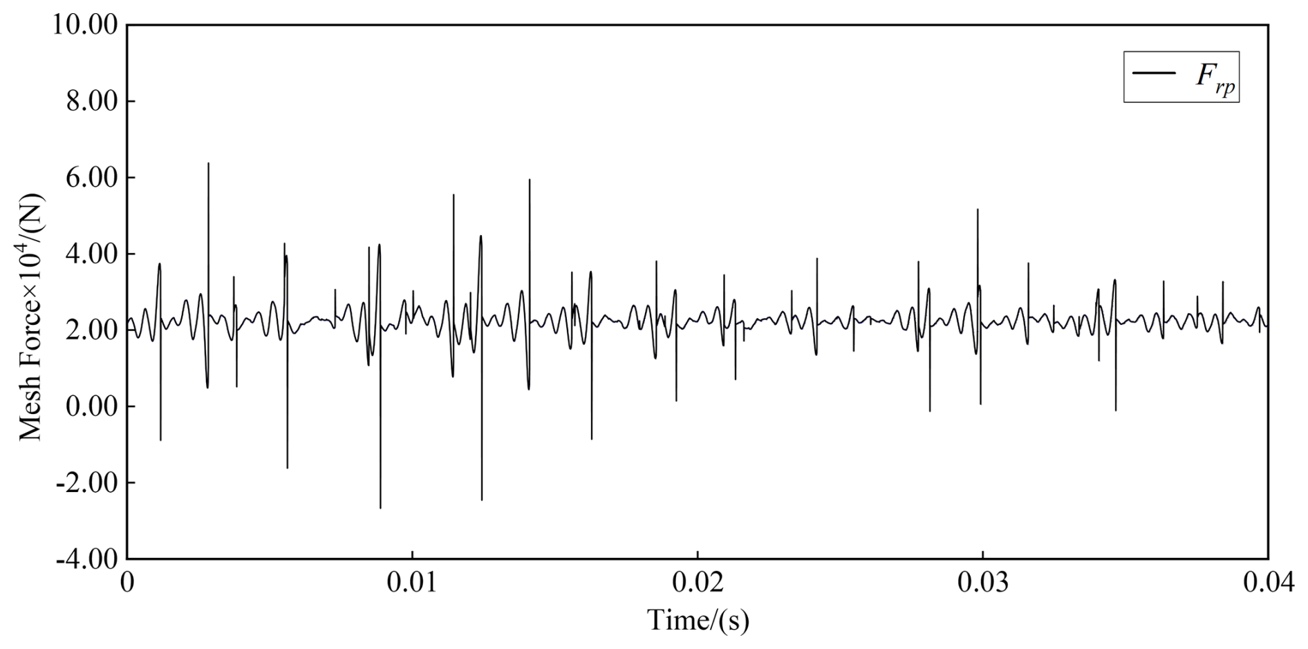
Figure 15Dynamic mesh forces of planet-ring mesh pairs only with random cumulative pitch errors in the time domain.
Figure 16 shows the FFT spectrum of Frp. Through comparison between Figs. 16a and 12d, the frequency components in the spectra of Frp become more complex across the full-frequency band due to the direct influence of the internal excitations caused by the floating ring gear's cumulative pitch errors. Rich frequency components appear in the spectrum, including fht, fap, fm, and their harmonics, as well as sidebands around fap, fm, and their harmonics. In Fig. 16a, the predominant frequency components are 2fap–11fht, 2fap–8fht, 2fap–3fht, and fm, and the corresponding amplitudes are 1492, 1201, 1012, and 914.3 N, respectively. Moreover, comparison of the partially enlarged views of the full-frequency spectra in Figs. 16 and 14 suggests that the fundamental components in these spectra are similar, whereas the amplitudes of frequency components in Fig. 16 are higher than those in Fig. 14.
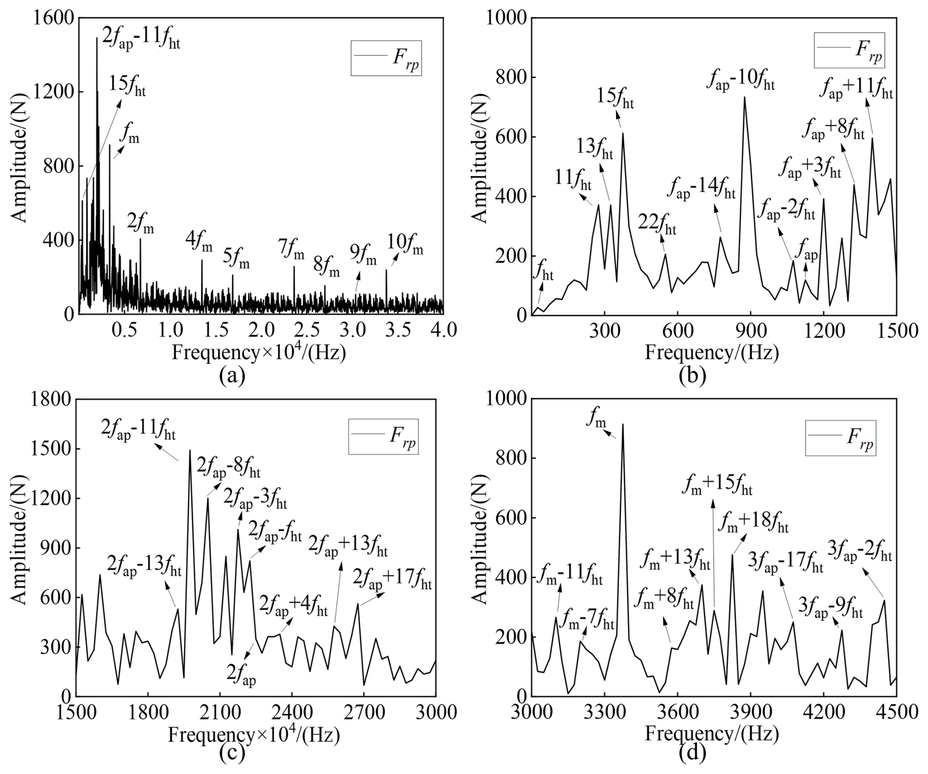
Figure 16Ring-planet dynamic mesh forces only with random cumulative pitch errors in the frequency domain: (a) full-frequency spectra, (b) partially enlarged view of the spectrum from 0–1500 Hz, (c) partially enlarged view of the spectrum from 1500–3000 Hz, and (d) partially enlarged view of the spectrum from 3000–4500.
5.3 Spectral characteristics of the HPGS with RCPE at varying speeds
To investigate the spectral characteristics of the system's dynamic response under varying-speed conditions, the dynamic mesh force spectra of both the external and the internal mesh pairs were computed over an input speed range of 20–12 000 rpm with a step size of 20 rpm, considering the influence of RCPE in the floating ring gear.
As shown in Fig. 17, the sun-planet mesh force spectrum exhibits not only the meshing frequency fm and its harmonics but also numerous sidebands around the meshing frequency, assembly phase frequency, and their harmonics due to the modulation by hunting tooth frequency fht and its harmonics – examples include fap + 3fht. The presence of such RCPE-induced frequency components in the sun-planet mesh force spectrum confirms the transmission of ring-gear error effects through the planetary gear train. Notably, within the speed range of 8000–12 000 rpm, the contributions of higher-order harmonics of fht – particularly 10fht and 11fht – dominate over the meshing frequency in the sun-planet mesh force spectrum, suggesting that the RCPE-induced dynamic excitations become the primary source of the sun-planet mesh force at high speeds.
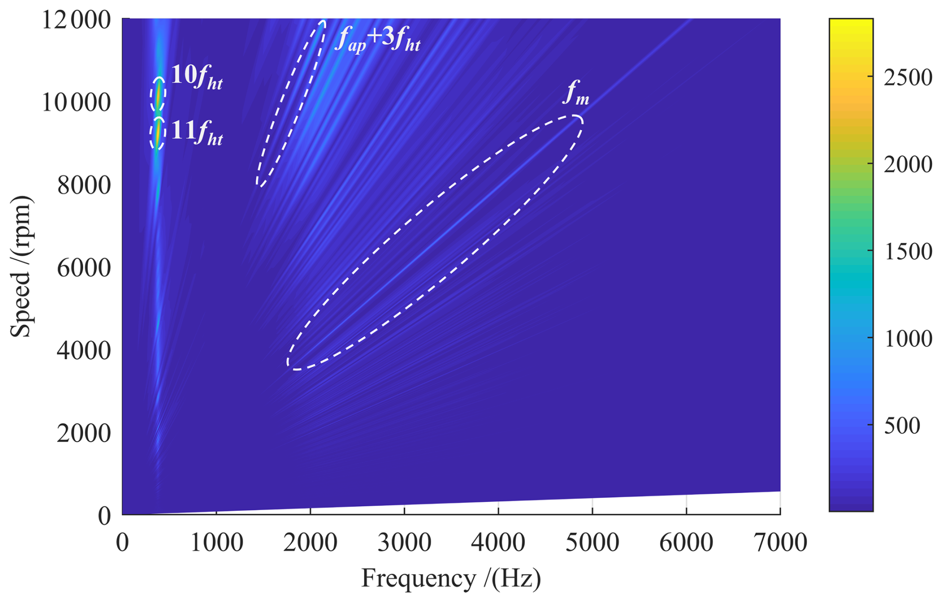
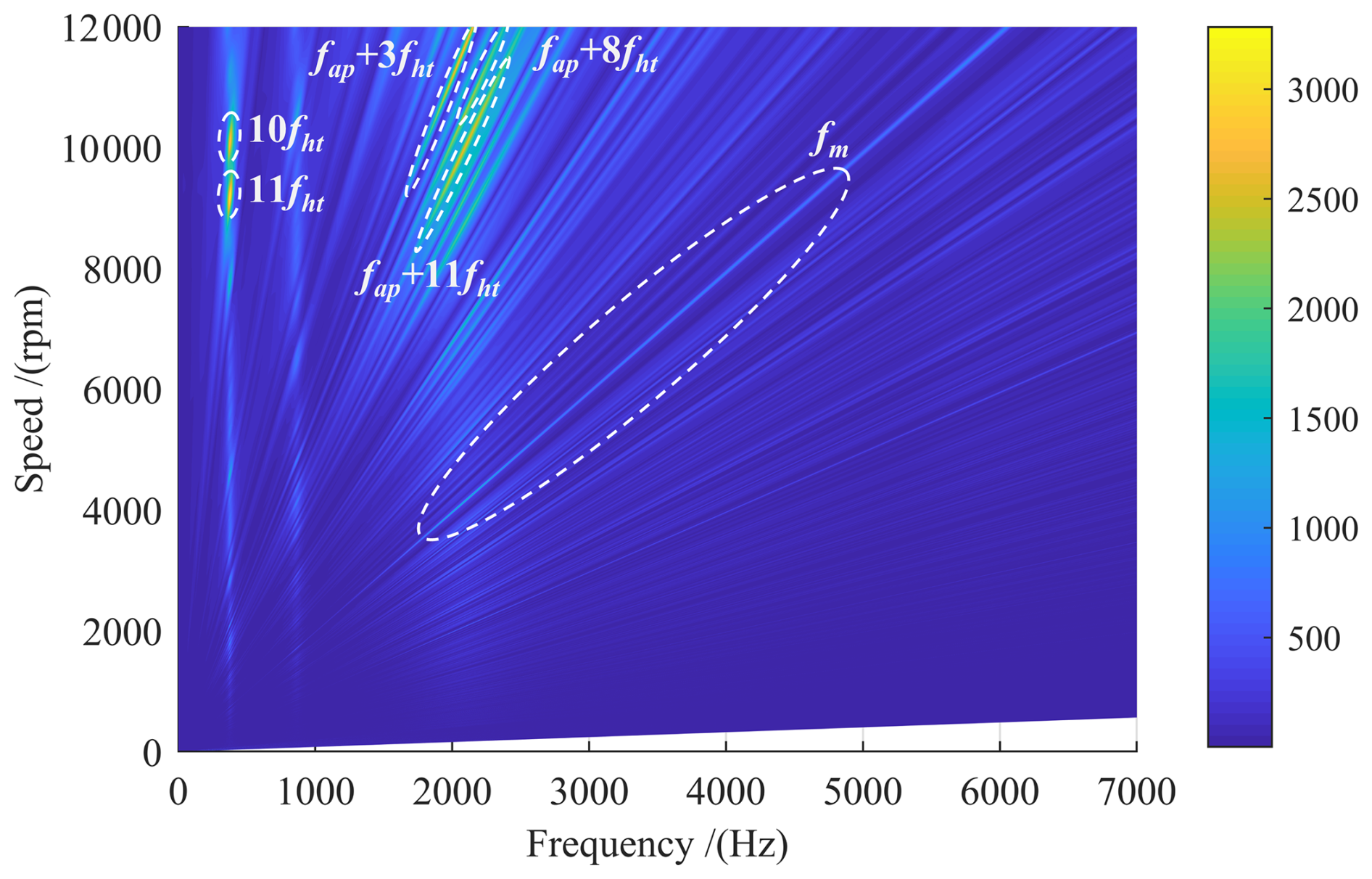
In contrast, the planet-ring mesh force spectrum (shown in Fig. 18) exhibits a richer set of spectral components, which include the meshing frequency, assembly phase frequency, and hunting tooth frequency, along with their harmonics and sidebands. This enhanced spectral complexity arises because the internal mesh pair is directly subjected to the floating ring gear's RCPE, resulting in stronger amplitudes for RCPE-related components compared to those observed in the external mesh pair. Within the same high-speed interval, the planet-ring mesh force is dominated by multiple RCPE-driven frequencies. The most prominent contributors are 10fht, 11fht, fap + 3fht, fap + 8fht, and fap + 11fht. Additionally, a distinct resonance band emerges near 378 Hz in both the internal and the external mesh force spectra. This phenomenon is attributed to resonant amplification triggered when harmonics of the RCPE-induced frequencies approach the system's sixth natural frequency (370 Hz) at specific rotational speeds.
In this paper, an improved mesh excitation calculation method with RCPE is constructed, and a lumped-parameter model for the HPGS is established. Based on these, the action of RCPE on mesh excitations under different loads is studied. Additionally, the dynamic mesh forces for all mesh pairs of the HPGS are investigated in detail, considering the effects of RCPE. The results demonstrate that RCPE fundamentally alters the system's dynamic characteristics. Under light loads, RCPE induces initial contact separations, leading to pronounced nonlinear contact loss and significant fluctuations in mesh forces. In the frequency domain, this manifests as the emergence of rich low-frequency components, including fht, fap, and their associated harmonics and sidebands. As the load increases, these nonlinear effects and low-frequency spectral contents diminish, with the response converging towards the classical spectrum dominated by fm and its harmonics. A critical outcome is the minimum repetition period of mesh forces extending to the hunting tooth period. Furthermore, the analysis uncovers a vibration-transfer phenomenon between sun-planet and planet-ring meshes, with the planet-ring mesh forces exhibiting a particularly complex full-spectrum response where the dominant component can shift to specific sidebands (e.g., 2fap–11fht).
From an engineering perspective, these results underscore several critical implications. For systems operating primarily under variable or light loads, achieving higher gear machining precision to control cumulative pitch errors is paramount for mitigating excessive vibration and noise. The distinct low-frequency spectral markers (e.g., fht, fap) induced by RCPE provide valuable fingerprints for condition monitoring and diagnostic algorithms, enabling more accurate health assessment and fault detection in complex planetary gearboxes. By clarifying the specific role of RCPE, this work provides a critical foundation. It is recognized, however, that in real-world applications, factors such as lubrication conditions, frictional variability, and temperature-dependent material properties interact in a coupled manner with such geometric imperfections. Future work will therefore focus on extending this modeling framework into a multi-physics simulation environment, specifically to investigate how RCPE, together with these factors, collectively influences the predicted mesh excitations and dynamic responses. Furthermore, while this study employs a normal distribution as a baseline to elucidate the fundamental impact mechanism of RCPE magnitude, the influence of different statistical distributions on the dynamic response remains an open and important question. Future work will also involve exploring the sensitivity of dynamic responses to various distributions of RCPE to further refine the model's predictive capability and practical relevance.
| Powe | Input power |
| nspe | Input shaft rotating speed |
| B1B2 | Actual line of action in the transverse plane |
| B2B3 | Face width of the helical gear pair |
| εγ | Total contact ratio |
| pbt | Transverse base pitch |
| xM, yM | Direction of the line of action and the face width |
| Δx | Distance between two adjacent discrete contact points along the xM direction |
| M | Total number of contact lines during gear engagement |
| N | Any integer bigger than 0 |
| nm | Total number of discrete contact points on the mth contact line |
| nall | Total number of all the theoretical discrete contact points |
| Fall | External force |
| P | The nth discrete contact point on the mth contact line |
| λmn | Global compliance of point P |
| Fmn | Normal force exerted on point P |
| δhmn | Local contact deformation of point P |
| εmn | Initial separation distance of point P before contact |
| dmn | Residual distance of point P after loading |
| LTE | Loaded transmission error |
| λbmn, λsmn, λamn, λfmn | Bending, shear, axial compression, and fillet-foundation compliance of P |
| d, h | Horizontal and vertical distances from point P to the dedendum circle and the central line of the tooth |
| Global compliance matrix for the gear pair | |
| , , , | Vectors of contact forces, contact deformations, initial separation distances, and the residual distances for all contact points |
| km | Mesh stiffness of the gear pair |
| , | Cumulative pitch error and pitch error of the kth gear tooth |
| The tooth number of the initial matching position of each gear | |
| Num | The number of meshing cycles required for tooth pair 1 to mesh again |
| now | The tooth pair that is about to engage |
| fm, fht, fap | Meshing, hunting tooth, and assembly phase frequency |
| Tht,Tm | Hunting tooth period and meshing period |
| δspi, δrpi | Elastic deformation of the sun-planet and ring-planet gear pairs along the mesh line direction |
| δcξi, δcηi, δczi | Elastic deformation on the ith planet-carrier mating pair |
| Fspi,Frpi | Mesh forces of the sun-planet and ring-planet gear pairs |
| Fcξi, Fcηi, Fczi | Bearing forces of the ith planet-carrier mating pair |
| φi | Position angle for the ith planet gear |
| s,i | Carrier, floating ring gear, sun gear, and the ith planet of the system |
| , gd,out | Input shaft, composite ring gear, and the ring gear of the system |
| kcξi, kcηi, kczi | Bearing stiffness between the carrier and the ith planet |
| klx, kly, klz | Supporting stiffness of the component l |
| , , , | Bending, compressive, and torsional stiffness between the left and right helical gears |
| kr_sl, kc_out, ksl_gd, kgdt | Torsional stiffness between two components |
| ccξi, ccηi, cczi | Bearing damping between the carrier and the ith planet |
| clx, cly, clz | Supporting damping of the component l |
| , , , | Bending, compressive, and torsional damping between the left and right helical gears |
| cin_sun, cr_sl, cc_out, csl_gd | Torsional damping between two components |
| , | Equivalent mass and actual mass of the corresponding component |
| Tin, Tout | Input and output torque |
| wt | Forces transmitted per unit width |
All the data used in this paper can be obtained upon request to the corresponding author.
YD and GL conceptualized the paper. YD wrote the paper. GL, LL, and BH reviewed the paper. YD, HQZ, and BXY edited the paper. All authors have read and agreed to the published version of the paper.
The contact author has declared that none of the authors has any competing interests.
Publisher's note: Copernicus Publications remains neutral with regard to jurisdictional claims made in the text, published maps, institutional affiliations, or any other geographical representation in this paper. The authors bear the ultimate responsibility for providing appropriate place names. Views expressed in the text are those of the authors and do not necessarily reflect the views of the publisher.
The authors appreciate the editors and reviewers for their efforts.
The work performed in this study is supported by the Key Program of the National Natural Science Foundation of China (grant no. 51535009), the National Key R&D Program of China (grant no. 2022YFB3402800), and the Fundamental Research Funds for the Central Universities.
This paper was edited by Pengyuan Zhao and reviewed by two anonymous referees.
Bi, Y., Dong, H., Liu, S.-S., Zhao, D.-N., Han, H., Zhang, D.-B., Hou, X.-Y., and Jin, G.-H.: Dynamic modeling and failure mechanism study of herringbone gear planetary transmission system for wind turbine under gear cracks, J. Renew. Sustain. Ener., 16, 055502, https://doi.org/10.1063/5.0231077, 2024.
Chang, L., Liu, G., and Wu, L.: A robust model for determining the mesh stiffness of cylindrical gears, Mech. Mach. Theory, 87, 93–114, https://doi.org/10.1016/j.mechmachtheory.2014.11.019, 2015.
Chang, L., Cao, X., He, Z., and Liu, G.: Load-related dynamic behaviors of a helical gear pair with tooth flank errors, J. Mech. Sci. Technol., 32, 1473–1487, https://doi.org/10.1007/s12206-018-0301-y, 2018.
Chen, J., Zhu, R., Chen, W., Li, M., Yin, X., and Zhang, X.: Research on pitch error phase matching of herringbone star gear system considering multi-tooth with different backlash, Acta Mech. Sinica, 40, 523331, https://doi.org/10.1007/s10409-023-23331-x, 2024.
Chen, J., Wan, Q., Zhu, R., and Chen, W.: Dynamic modeling and analysis of herringbone star gear system considering pin misalignment and error phase combination, Mech. Syst. Signal Pr., 224, 112243, https://doi.org/10.1016/j.ymssp.2024.112243, 2025.
Czakó, A., Øehák, K., Prokop, A., Rekem, J., Láštic, D., and Trochta, M.: Static transmission error measurement of various gear-shaft systems by finite element analysis, Journal of Measurements in Engineering, 12, 183–198, https://doi.org/10.21595/jme.2023.23843, 2024.
Fernández-del-Rincón, A., Iglesias, M., de-Juan, A., Diez-Ibarbia, A., García, P., and Viadero, F.: Gear transmission dynamics: effects of index and run out errors, Appl. Acoust., 108, 63–83, https://doi.org/10.1016/j.apacoust.2015.11.012, 2016.
Gong, J., Liu, G., Liu, L., Yuan, B., Yang, L., and Ren, P.: Experimental study on vibration characteristics of double-helical gearbox with isolators, J. Mech. Sci. Technol., 36, 4379–4393, https://doi.org/10.1007/s12206-022-0803-5, 2022.
Guo, F. and Fang, Z.: The statistical analysis of the dynamic performance of a gear system considering random manufacturing errors under different levels of machining precision, Proceedings of the Institution of Mechanical Engineers, Part K: Journal of Multi-body Dynamics, 234, 3–18, https://doi.org/10.1177/1464419319862165, 2020.
Han, B., Li, H., Zhang, Z., Song, L., Wang, J., Lv, X., and Wang, J.: A novel construction method of planetary gear dynamics model under indexing circle crack failure, J. Vib. Eng. Technol., 13, 251, https://doi.org/10.1007/s42417-025-01769-x, 2025.
Hong, J., Talbot, D., and Kahraman, A.: Effects of tooth indexing errors on load distribution and tooth load sharing of splines under combined loading conditions, J. Mech. Design, 137, 032601, https://doi.org/10.1115/1.4029282, 2015.
Hu, C., Yuan, T., Yang, S., Hu, Y., and Liang, X.: Dynamic load sharing behavior for the pitch drive in MW wind turbines, Processes, 11, 544, https://doi.org/10.3390/pr11020544, 2023.
Hu, Y. and Zhang, C.: A new semi-analytical slice model for elastic contact analysis of herringbone gears, J. Mech. Sci. Technol., 39, 757–765, https://doi.org/10.1007/s12206-025-0120-x, 2025.
Huang, W., Hu, H., and Ma, H.: Dynamic modeling and response analysis of cracked herringbone gear transmission systems with installation errors, Mech. Mach. Theory, 206, 105924, https://doi.org/10.1016/j.mechmachtheory.2025.105924, 2025.
Huo, G., Iglesias-Santamaria, M., Zhang, X., Sanchez-Espiga, J., Caso-Fernandez, E., Jiao, Y., and Viadero-Rueda, F.: Influence of eccentricity error on the orbit of a two-stage double-helical compound planetary gear train with different mesh phasing configurations, Mech. Mach. Theory, 196, 105634, https://doi.org/10.1016/j.mechmachtheory.2024.105634, 2024.
Inalpolat, M. and Kahraman, A.: A dynamic model to predict modulation sidebands of a planetary gear set having manufacturing errors, J. Sound Vib., 329, 371–393, https://doi.org/10.1016/j.jsv.2009.09.022, 2010.
Inalpolat, M., Handschuh, M., and Kahraman, A.: Influence of indexing errors on dynamic response of spur gear pairs, Mech. Syst. Signal Pr., 60–61, 391–405, https://doi.org/10.1016/j.ymssp.2014.11.017, 2015.
ISO: Cylindrical gears-ISO system of flank tolerance classification-Part 1: Definitions and allowable values of deviations relevant to flanks of gear teeth, International Organization for Standardization (ISO), ISO 1328-1:2013, https://www.iso.org/obp/ui/en/#iso:std:iso:1328:-1:ed-2:v1:en (last access: 5 February 2026), 2013.
Li, M., Yang, Z., and Xie, L.: Effect of planet pin position errors on the fatigue reliability of large aviation planetary systems, Frontiers of Mechanical Engineering, 19, 29, https://doi.org/10.1007/s11465-024-0797-z, 2024.
Liu, J., Li, X., and Xia, M.: A dynamic model for the planetary bearings in a double planetary gear set, Mech. Syst. Signal Pr., 194, 110257, https://doi.org/10.1016/j.ymssp.2023.110257, 2023.
Pedrero, J. I., Sánchez, M. B., and Pleguezuelos, M.: Analytical model of meshing stiffness, load sharing, and transmission error for internal spur gears with profile modification, Mech. Mach. Theory, 197, 105650, https://doi.org/10.1016/j.mechmachtheory.2024.105650, 2024.
Sainsot, P., Velex, P., and Duverger, O.: Contribution of gear body to tooth deflections – a new bidimensional analytical formula, J. Mech. Design, 126, 748–752, https://doi.org/10.1115/1.1758252, 2004.
Sharma, S. K., Kumar, N., Avesh, M., Sharma, R. C., Siddiqui, M. I. H., and Lee, J.: Navigating tranquillity with H8 controller to mitigate ship propeller shaft vibration, J. Vib. Eng. Technol., 12, 7969–7979, https://doi.org/10.1007/s42417-024-01340-0, 2024a.
Sharma, S. K., Sharma, R. C., Mohapatra, S., Fouly, A., Hossain, I., and Lee, J.: Technological advancements in oscillation reduction for propulsion shaft systems, J. Vib. Eng. Technol., 12, 1779–1797, https://doi.org/10.1007/s42417-024-01503-z, 2024b.
Sharma, S. K., Sharma, R. C., and Lee, J.: Propelling precision of longitudinal vibration mitigation in ship propeller shafts through advanced nonlinear intelligent semi-active control leveraging adaptive neuro-fuzzy inference system with linear quadratic regulator, J. Vib. Control, 31, 1472–1484, https://doi.org/10.1177/10775463241244836, 2025.
Shehata, A., Adnan, M. A., and Mohammed, O. D.: Modeling the effect of misalignment and tooth microgeometry on helical gear pair in mesh, Eng. Fail. Anal., 106, 104190, https://doi.org/10.1016/j.engfailanal.2019.104190, 2019.
Talbot, D., Sun, A., and Kahraman, A.: Impact of tooth indexing errors on dynamic factors of spur gears: experiments and model simulations, J. Mech. Design, 138, 093302, https://doi.org/10.1115/1.4034175, 2016.
Wang, F., Xu, X., Fang, Z., and Chen, L.: Study of the influence mechanism of pitch deviation on cylindrical helical gear meshing stiffness and vibration noise, Adv. Mech. Eng., 9, 168781401772058, https://doi.org/10.1177/1687814017720586, 2017.
Wang, S. and Zhu, R.: An improved mesh stiffness model for double-helical gear pair with spalling defects considering time-varying friction coefficient under mixed EHL, Eng. Fail. Anal., 121, 105174, https://doi.org/10.1016/j.engfailanal.2020.105174, 2021.
Wang, S. and Zhu, R.: An improved mesh stiffness model of helical gear pair considering axial mesh force and friction force influenced by surface roughness under EHL condition, Appl. Math. Model., 102, 453–471, https://doi.org/10.1016/j.apm.2021.10.007, 2022.
Wang, S. and Zhu, R.: Research on dynamics and failure mechanism of herringbone planetary gearbox in wind turbine under gear surface pitting, Eng. Fail. Anal., 146, 107130, https://doi.org/10.1016/j.engfailanal.2023.107130, 2023.
Xu, X., Ge, H., Wu, H., and Jia, H.: Research on nonlinear characteristics of herringbone planetary gear transmission system considering double-sided meshing impact, Nonlinear Dynam., 112, 3195–3215, https://doi.org/10.1007/s11071-023-09201-3, 2024.
Yang, H., Shi, W., Chen, Z., and Guo, N.: An improved analytical method for mesh stiffness calculation of helical gear pair considering time-varying backlash, Mech. Syst. Signal Pr., 170, 108882, https://doi.org/10.1016/j.ymssp.2022.108882, 2022a.
Yang, J., Lin, T., He, Z., and Chen, M.: Novel calculation method for dynamic excitation of modified double-helical gear transmission, Mech. Mach. Theory, 167, 104467, https://doi.org/10.1016/j.mechmachtheory.2021.104467, 2022b.
Yang, J., Zhu, R., Lee, H., Li, M., and Yin, X.: Experimental and numerical dynamic analysis of marine herringbone planetary gearbox supported by journal bearings, J. Sound Vib., 545, https://doi.org/10.1016/j.jsv.2022.117426, 2023.
Yang, L., Chen, Q., Yin, L., Wang, L., and Shao, Y.: Dynamic characteristic of spur gear system with spalling fault considering tooth pitch error, Qual. Reliab. Eng. Int., 38, 2921–2938, https://doi.org/10.1002/qre.2869, 2022c.
Yuan, B., Chang, S., Liu, G., and Wu, L.-Y.: Quasi-static and dynamic behaviors of helical gear system with manufacturing errors, Chin. J. Mech. Eng., 31, 30, https://doi.org/10.1186/s10033-018-0238-1, 2018.
Zhang, T., Lin, T., and Fu, L.: Analytical and experimental study on acoustic-vibration characteristics of double-helical planetary gear transmission systems with multi-field coupling effect, Mech. Syst. Signal Pr., 224, 112143, https://doi.org/10.1016/j.ymssp.2024.112143, 2025.
- Abstract
- Introduction
- Description of the models
- Quasi-static analysis
- Analysis of frequency-domain mesh excitations with RCPE
- Dynamic response analysis
- Conclusions
- Appendix A: Nomenclature
- Data availability
- Author contributions
- Competing interests
- Disclaimer
- Acknowledgements
- Financial support
- Review statement
- References